1
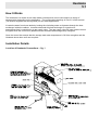
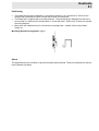
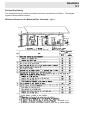
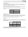
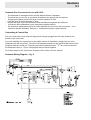
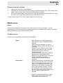
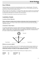
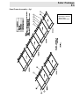
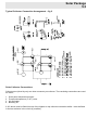
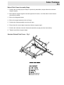
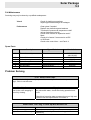
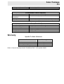
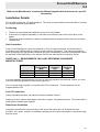
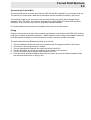
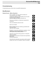
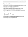
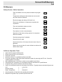
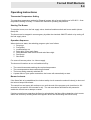
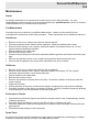
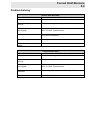
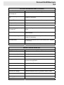
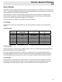
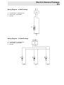
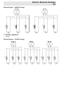
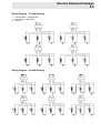
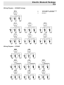
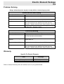
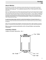
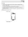
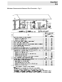
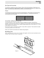
Part 5.0 Heat Sources Title Section Heatmate 5.1 Solar Collectors 5.2 Forced Draft Burners 5.3 Electric Element Package 5.4 Comfort 5.5 05/07 Heatmate 5.1 How It Works The Heatmate is a closed circuit water heater circulator that can be connected to a variety of storage tanks depending on the application. The configuration drawings in Part 2.0 of this manual (Full manual supplied with storage tank) set out these applications. It heats the water from these tanks by heating the circulating water as it passes through the heat exchanger inside the cabinet. Located underneath this heat exchanger is a gas burner arrangement that is controlled by a gas supply valve. The gas supply valve will open and the burner will ignite when the control box (attached to the Heatmate and storage tank) energises. Once the control box senses that the storage tank water temperature is OK it de-energises and the Heatmate shuts down until next required. Installation Details Location of Heatmate Connections – fig. 1 Heatmate 5.1 Positioning • • • The Heatmate should be installed in a convenient position up to a maximum of 10m from the storage tank (otherwise the flow of water will become too restricted). The Heatmate is supplied with mounting brackets. These brackets are designed for the unit to be mounted to a wall near the storage tank or on the tank itself. Refer to fig. 2 below for bracket mounting diagram. More than one Heatmate can be connected to a storage tank – details of this are provided further on. Mounting Bracket Arrangement – fig. 2 Stand The Heatmate may be mounted on ground-mounted special stands. These are available on request from Edwards Hot Water. Heatmate 5.1 External Positioning The Heatmate must be located in accordance with the requirements of AS5601. The diagram opposite shows suitable locations. Minimum Clearances for Balanced Flue Terminals – fig. 3 Heatmate 5.1 Incoming Flow Line The Heatmate 250 model has a 20 BSP female coupling (see fig. 1). It is used to connect the incoming water supply pipe from the storage tank. An isolating valve must be fitted between the Heatmate and the storage tank for easier servicing. A check valve and 2 x pressure & temperature relief valve must be installed in this line after each Heatmate when connecting to a direct tank. The lines should be insulated. This main line should be sized to suit the number of Heatmates that are being connected together as follows: No. of Heatmates 1 2 3 4 Pipe Size 25mm 40mm 50mm 65mm Outgoing Return Line The Heatmate 250 model has a 25mm copper starter pipe (see fig. 1). It is used to connect the outgoing water supply pipe back to the storage tank. An isolating valve must also be installed for easier serving and the line sized the same way as shown above for the Incoming Line. The main return line should be sized as shown above for the flow line. Gas Supply Refer to fig. 1 for the location of the 20mm BSP socket gas connection for each Heatmate. The gas pipe should be sized in accordance with AS5601. The table below provides a guide for the main incoming gas supply: No. of Heatmates 1 2 3 4 Heatmate 250 Natural Gas LPG 1.25kPa 20mm 25mm 40mm 50mm 2.75kPa 20mm 20mm 25mm 25mm If you are installing natural gas and you have an inlet gas pressure that exceeds 1.7 kPa, you must fit a second stage regulator into the incoming gas line. Also, a second stage regulator is required to all LPG connections. These regulators are not supplied with the unit. Heatmate 5.1 Heatmate Gas Conversion for use with LPG: - The Heatmate is manufactured for use with Natural Gas as a standard. To convert the unit to LPG, a conversion kit and two new gas jets will be required. The gas jets supplied for NG use have an orifice diameter of 5mm. LPG jets have an orifice diameter of 3mm. NG jets will need to be removed from burner manifold and replaced with LPG jets. Conversion Kit modifications as per instructions supplied with Kit. Kit contains a replacement jet with an orifice diameter of 0.01mm for pilot conversion. Jet is located in the pilot assembly. Remove ¼” compression fitting to replace pilot jet. Connecting A Control Box The unit comes with a 4-pin lead and plug which is simply plugged into the 4-pin socket on the bottom of the control box. If you are installing one control box for a multiple number of Heatmates, simply plug one of the Heatmates into the control box. Plug the next Heatmate directly into the socket at the bottom of the Heatmate with the control box. Then plug any other Heatmates (the 3rd, 4th etc.) into the socket of the Heatmate next to it. Figure 5 shows how they are linked together. For further details on the control box if needed, refer to Part 4.0 of the manual. Heatmate Wiring Diagram – fig. 4 Heatmate 5.1 Manifolding Heatmates together – fig. 5 Filling the Heatmate with Water The Heatmate is filled up as part of the procedure for filling the storage tank. Follow the instructions provided for the storage tank. Make sure that air has been bled from the heat exchanger by opening the air bleed valve shown below: Heatmate 5.1 Commissioning Commissioning may only be done by a qualified tradesperson. Before trying to fire up the Heatmate ensure that the checklist below is completed. Completion Checklist All gas components are secure and wiring in place. Unit is filled with water. Isolating valves are open. Gendex water treatment has been added if applicable. Heat exchanger has been purged of air. Circulating pump primed with water to prevent burning out. Unscrew seal screw at end of motor and tighten once water flows. Control Box thermostats are set to the desired temperature. Pump set to MAXIMUM speed. ‘Firing Up’ the Heatmate Each Heatmate comes with a gas control valve. This valve (shown in fig. 7) has the necessary controls for starting the Heatmate. Fig. 7 Heatmate 5.1 Firing Up Sequence Of Steps 1. 2. 3. Remove the front cover of the Heatmate. Remember to ensure that the Commissioning Checklist has been done. That is mainly that power, water and gas have all been completed and are available. Turn on the power supply to the control box– this will automatically activate the pump, and the Gas Control valve should allow gas to the burner and fire up. To shut down the burner, turn off the power supply to the control box. Maintenance Owner No specific maintenance is required by the owner as the unit is fully automatic. It is your responsibility to ensure that the unit is serviced regularly by a qualified person (every 12 months) – contact Edwards for your nearest service provider. Full Maintenance Servicing may only be done by a qualified tradesperson. Visual Performance Open the front cover and inspect the air ways and flue ways for debris and clear if required. Check the heat exchanger for signs of corrosion, debris or obstructions and clear if required. Check the burner blades for any foreign matter or build-ups and clear if required. Check that the pump is set on the maximum position. In high TDS areas clean pump impeller & deposits from inside pump housing Check for any gas leaks using a soap rich solution and rectify if necessary. Clean flow switch paddle and check operation. Check the performance of the safety relief valves by opening the lever and closing it again. If connected to treated water, be careful not to discharge very much water. Check the burner rating by checking the burner gas operating pressure. Connect the manometer to the test nipple on the gas valve and check with the data plate on the unit. Adjust the gas pressure if required. Check the water treatment level is good – this is usually done as part of the tank maintenance (see section 3.0) Heatmate 5.1 Spare Parts Description Isolating Valves Support Brackets Combination Gas Control Valve Over-temperature Thermostat Water Flow Switch Circulating Pump Burner P & T Valve Heatmate 250 Model 25mm BSP Ball type Edwards Honeywell SV9605 (NOV 00 - ) Honeywell VR8305P(94-00) Derwent 24V, 97°C manual reset Caleffi 24V Grundfos UPS 20 – 60B (10/00-) Polidoro ribbon type RMC HTE 575 – 1000kPa (2 off) Stock Code 2020309 2020160 2020381 2020365 6060300 6060299 56860242 2030188 2020331 Problem Solving Heater Fails to Light Possible Cause Gas supply turned off or too low. Power supply turned off. Remedy Open isolating valve or readjust regulator if necessary. Flow switch activated. Check heat exchanger is full of water and there are no air locks. Bleed air from heat exchanger using bleed valve. Flow switch contacts should be closed when pump is running. Over-temperature thermostat activated. Press reset button on thermostat located on the Heatmate (not control box). If it is a controlled temperature control box check the reset button on the over temperature thermostat. Manifolded Heatmates burners are not connected together. Check that each Heatmate is plugged into the one next to it. Control box is faulty. Make sure operating thermostat is calling for heat. Replace control box. Check lead from control box is plugged in. If OK there will be a temperature reading on the panel. Turn off the power supply for 30 seconds to reset the system. Heatmate 5.1 Noisy operation Possible Cause Air in heat exchanger. Remedy Bleed air from the heat exchanger by opening the bleed valve. Pump speed set too low. Set pump speed to MAXIMUM setting. Pump run on timer incorrect. Check that timer is wired so that the timer runs for 4 minutes after the pump shuts down. Temperature setting too high on control box thermostat Reset the operating temperature to a maximum of 82°C for SV tanks & 65°C for LEX tanks. Safety Valve Drips – for SV tank only The valve on the Heatmate is a safety valve and should only release water in the event of a problem. Possible Cause Cold water expansion is not fitted to tank or is faulty. Remedy Fit a 700kPa cold water expansion valve into cold water line or remove the valve, flush the valve with water, check the closing operation and re-fit. Unstable Burner Performance Possible Cause Gas pressure is incorrect. Remedy Check gas pressure is within the required pressure specified on the data plate. Insufficient air is available to burn. Check flueways and airways for debris and blockages. Warranty Specific To Heatmate Item Heat Exchanger Associated parts- valves Labour, Travel & Freight Coverage 3 years full cover 4th year 75% cover 5th year 50% cover 1 year 1 year Refer to General Warranty terms & Conditions (Part 1.3) for greater details. Solar Package 5.3 How It Works Edwards design their commercial solar packages as an ‘active’ or pumped system. This forced circulation of water through the solar collectors effectively ‘scrubs’ more available energy from the panels than conventional thermosiphon systems. When the water in the solar panels is 7°C higher than the water near the bottom of the storage tank, the solar control box turns the pump on and water is circulated from the tank to the collectors until the temperature differential is 2°C and then it turns the pump off. Full details of the operation of the solar control box are in Part 4.3. Installation Details Location of Solar Collectors Before commencing installing the solar collectors, inspect the roof structure to ensure that the solar panels are located on an area of the roof that will be unshaded all year. Carefully check high buildings or trees in the vicinity for winter shade. If needed, discuss with the client the lopping or removal of any trees. Orientation of Solar Panels For optimum performance, the solar collectors should be installed facing towards the equator. Always check the orientation and use a compass. Variations up to 45° east or west will have minimal effect on the annual solar contribution (less than 5%). Variations above 45° east or west will require additional solar collectors. Equator 45° 45° East/West East/West Minimum Inclination (angle) The most common installation uses a roof of 18° pitch but solar collectors may be installed on an angle that varies from the latitude angle up to +/- 20%. This will have minimal effect on the total annual solar contribution (less than 5%). Roof pitches below the minimum recommended angles shown below will require a ‘raised pitch’ frame available from Edwards. Minimum inclination angles for locations south of the tropic of Capricorn (23.5°): Adelaide Brisbane Perth 15° 10° 15° Alice Springs 10° Melbourne 18° Sydney 15° 05/07 Solar Package 5.3 Cyclonic Areas Only solar collectors that are marked by Edwards as suitable should be installed in cyclonic areas. Frost-Prone Areas Any areas that have recorded temperatures of 1°C or less must have anti-freeze protection for the solar collectors - if this has not been supplied contact Edwards. If installation is in an area that is subject to temperatures below -6°C, further anti-freeze protection may be required - contact Edwards for advice. NOTE: When solar collectors have been installed on the roof, do not expose them to the sun without water in them for prolonged periods. Arrange for them to be covered with shade cloth or similar. Collector Frame Requirements – Table 1 The table below details what frames go with what configuration and number of solar collectors. Total Number of Solar Collectors Number of Rows of Solar Collectors Number of Solar Collectors per Row 2 4 1 1 2 1 2 1 2 1 2 1 2 1 2 2 4 2 4 2 5 3 4 2 4 2 6 3 10 5 16 8 20 10 24 12 16 8 20 10 25 10 20 15 6 10 16 20 24 32 40 50 60 Frame Type and Number Required 305 Cyclone 440 Cyclone Frame Frame 1 2 2 2 2 2 2 2 2 2 4 2 4 1 6 4 4 8 8 4 8 4 8 2 12 8 8 4 14 10 10 3 18 20 Solar Package 5.3 Fitting the Solar Collectors Refer to Table 1 & Figure 1 for frame assembly layout, and Figure 2 for collectors connection when following these instructions. If fitting ‘Raised pitch’ frames see Table 1 & Figure 3. 1. Protect any gutters from damage due to ladders or collectors being hauled up to the roof. A block of wood with carpet nailed to it is recommended for this purpose. 2. Position the ladder and check the condition of the roof. Advise the customer of any broken tiles. 3. Assemble mounting trays on the ground. Secure the roof trays (2) to the top of roof trays (1) with tek screws. 4. Bolt the collector support (3 & 4) to roof tray (2) using the existing holes. 5. Position on the roof so that the frame sits over two roof rafters for support. 6. Using appropriate length coach bolts, secure to rafters through roof trays in each corner. 7. Lift the solar collectors onto the roof one at a time. Rest the collectors against the gutter and support it from the ground. Pull up the collectors from the roof. 8. Slide the collectors into position on the frame and assemble the panels. 9. A coat of non-hardening, high temperature grease should be applied to union nuts before installation. 10. Connect the collectors together using the inter-connectors provided (in series). A diagram should be provided specifically for the configuration you are installing; it is not part of this manual – contact Edwards if you do not have one. 11. Fit the starter pipes. 12. Fit the sensor pockets. 13. Fit the P & T valves. 14. Fit the air eliminators. 15. Blank off the remaining collectors connections with brass panel nuts and blanking discs. Ensure that fibre washers are fitted to all collector connections. Blanking discs should be installed with the smooth edge facing into the solar collectors. 16. Fit the top collectors support angle into position. Remove a row of tiles above the angle, hook fixing straps into the top collector support angle and fasten to the rafters, making sure the angle is pulled tight whilst the lip still covers the edge of the solar collector. 17. Peel the protective plastic coating off the collectors. If left on and exposed to sunlight it will discolour. Solar Package 5.3 Panel Frame Assembly – fig 1 The collectors overhang the frames – allow a gap between frame sets. Solar Package 5.3 Typical Collector Connection Arrangement – fig 2 Solar Collector Connections Collectors are joined by only one inter-connector per collector. The remaining connections are used fro either; 1. 2. 3. 4. Solar panel temperature sensor Pressure/temperature (P & T) valve Air eliminator Blanking off 2 & 3 above must be fitted into one of the highest or top collector connection whilst 1 must be fitted in the last collector in the circuit (if possible). Solar Package 5.3 Raised Pitch Frame Assembly Steps 1. Position the roof trays (as per steps 3-6 previously described, except without the collector support angles). 2. Bolt collector support angles to left and right side A frames – the flush side of the A frames should face inwards. 3. Bolt on the diagonal braces. 4. Bolt on the angle brackets to the roof trays. 5. Position the frame assembly onto the roof trays. 6. Ensure that all nuts are tight except top collector support angle. 7. Position the collectors onto the frame and assemble (as per previous instructions). 8. Tighten top collector support angle. Standard Raised Pitch Frame – Fig 3 Solar Package 5.3 Incoming (Solar Flow) Line The line to the solar collectors should be sized in accordance with the pump size and flow rates. Refer to Table 2 for indicative sizes. The line should be connected to the storage tank and to the furthest end of the solar collectors. The location of the tank connection is shown in Parts 2.0 & 3.0. The line should be insulated in UV resistant insulation. Line Sizes – Table 2 Number of Solar Collectors 2 4 6 10 16 20 24 32 40 50 60 Flow Rate Required Litres/second 0.1 0.2 0.3 0.5 0.8 1.0 1.2 1.6 2.0 2.5 3.0 Line Size Millimetres Based on 30m run 15 20 20 25 25 40 40 40 50 50 50 Outgoing (Solar Return) Line The line from the solar collectors should be sized in accordance with the pump size and flow rates as per Table 2. The line should be connected to the storage tank and to the nearest end of the solar collectors. The location of the tank connection is shown in Parts 2.0 & 3.0. The line should be insulated in UV resistant insulation. Solar Circulation Pump Install the pump so that it draws from the storage tank and ‘delivers’ the water to the collectors. The pump should be installed in the flow line to the collectors within 2 metres of the storage tank. It is connected to the solar control box (see Part 4.3). Make sure that the pump speed is set on the maximum setting. Expansion Tank If the solar collectors are connected to an LEX or SHX tank than the expansion tank must be installed above the highest part of the solar collector circuit to ensure that it is always fully flooded. Filling with Water Ensure that all valves eg. isolating, P & T and air eliminators in the solar circuit are open to allow air to escape from the circuit when filling with water. Follow the tank filling instructions provided in Part 3.0 if needed. Solar Package 5.3 Commissioning Commissioning may only be done by a qualified tradesperson. Completion Checklist Tank and circuit is filled with water. Isolating valves are open. Gendex water treatment has been added if it is a LEX, GXC, TC or SHX tank. Circuit has been purged of air. Circulating pump primed with water to prevent burning out. Unscrew seal screw at end of motor and tighten once water flows. Solar Control Box is set up and sensor cables are fitted to tank and panels and wired to the pump. Pump set to maximum speed and all fittings are watertight. Maintenance Owner No specific maintenance is required by the owner as the unit is fully automatic. It is your responsibility to ensure that the unit is serviced regularly by a qualified person (every 12 months) – contact Edwards for your nearest service provider. Do not switch off the power to the solar control box. If power is cut or disconnected, the solar collectors must be covered. Annually prune any trees or shrubs that may be shading the collectors. If buildings are shading them by no more than 10% then that is OK. Replacement of the glass in solar collectors should be claimed under insurance – it is hazardous and should only be carried out by a suitably qualified trades-person. Solar Package 5.3 Full Maintenance Servicing may only be done by a qualified tradesperson. Visual Check for leaking connections Inspect pipework flashings for leakages Performance Clean glass if needed Replace any defective panel washers Test that the pressure & temperature relief valves discharge correctly Check level of water in expansion tank if fitted. Check pH of water if connected to a LEX or SHX tank Check solar control box – see Part 4.4 Spare Parts Description Type / Model 1 Frame Assembly Edwards 2 3 4 5 6 7 Solar Collectors Interconnectors Solar Control Box Circulating Pump Air eliminator P & T Valve Edwards Edwards Edwards As supplied Robocal Caleffi RMC HT575 – 850 kPa Stock Code 305-1016190 440-101106 67092 50075 330695 907045 2020335 220612 Problem Solving P & T Relief Valve Drips A relief valve is designed to drip as part of its normal operation when temperatures are high. If this is not the case: Possible Cause Dirt has built up under the seal in the valve stopping it from fully closing. Remedy Turn off the cold water supply, remove the valve, flush the valve with water, check the closing operation and re-fit. Check that incoming water pressure is not too high and valves meet the requirements of AS3500.4 Water takes Too Long To Heat Up With Booster Off Possible Cause Cloudy or cool day System too small for usage Remedy No action Have size checked by Edwards and upgrade if necessary. Solar Package 5.3 Leaking water lines or fittings Solar Control Box fault Check and repair if necessary. See part 4.3 Condensation in Solar Collectors Possible Cause Water was present at installation Leaking inside collector Glass has a crack Remedy This will eventually evaporate. New collector is required. Replace collector glass or seal with silicon if possible. Solar Pump Does Not Run Possible Cause Solar Control Box fault Power turned off Faulty pump Faulty sensors Remedy See Part 4.3 Turn power supply on. Repair or replace. See Part 4.3 Warranty Specific To Solar Collectors Item Panel Associated parts- valves Labour, Travel & Freight Coverage 3 years 1 year 1 year Refer to General Warranty terms & Conditions (Part 1.3) for greater details. Forced Draft Burners 5.4 Refer to the Manufacturer’s Instruction Manual supplied with the burner for specific information. Installation Details Forced draft burners are a Type B appliance. They may only be installed, commissioned or serviced by a suitably qualified trades-person. Positioning • • • The burner may already be positioned on the front of the heater. If the burner is supplied separately, it will need to be bolted in place on the front door of the heater. The burner must be located in a stable, weatherproofed environment that is free from air-borne contaminants. Gas Connection If the Forced Draft Burner is gas fired (Natural or LPG), the gas connection should be made in accordance with AS5601 and any other local gas authority regulations. The pipe-work should be sized according to the gas pressure and flow rate (gas consumption) required. These details should be provided on the Data Plate on the Heater. Refer to the table below for indicative figures. GUIDE ONLY – REQUIREMENTS CAN VARY DEPENDING ON BURNER MANUFACTURER HEV Model HEV95/490 HEV330/490 HEV330/1000 Gas Consumption MJ/h 646 646 1318 Natural Gas Pressure kPa 2.0 2.0 2.5 LPG Pressure kPa 1.5 1.5 2.0 If you are installing natural gas and you have an inlet gas pressure that exceeds 5.0kPa, you must fit a second stage regulator into the incoming gas line. Also, a second stage regulator is required to all LPG connections. These regulators are not supplied with the unit. Fuel Oil Connection Unless otherwise specified, fuel should be light oil distillate Class D. Supply and return (where fitted) pipes should be in copper, not galvanised steel. Final connection is made with the flexible pipe supplied. Plant Room Ventilation Ventilation requirements vary according to the size of the heater but it is essential that it be provided. As a guide, 160mm² of ventilation opening per MJ of gas consumption is required at high and low levels. 05/07 Forced Draft Burners 5.4 Connecting A Control Box The forced draft burner must be wired into the HEV Control Box supplied (if it not already done so). The control box comes with a lead that is hard wired into the terminals provided on the burner. The electrical supply is via. this control box and comes with a 3 pin plug that is plugged into a standard 240V, 10A GPO. All electrical components are 240V 50Hz AC unless when specified otherwise. Ensure that wiring is done to Australian Standard AS3000. For further details on the control box if needed, refer to Part 4.0 of the manual. Fluing All gas or oil burners must have flues designed and installed in accordance with EPA, AGA and any local gas or building authorities regulations. AS5601 details correct sizing and installation however, reference should be made to local requirements for other countries outside of Australia. The preferred criteria that Edwards specifies for a flue are: 1. 2. 3. 4. 5. 6. The inner diameter of the flue must not be less than the flue spigot provided on the heater. The minimum flue length must be 3 metres. The flue temperature inside the first metre should be 200-220°C. The flue should be as vertical as possible from the heater to the terminal. The flue should provide a positive draft (up-flow) of 5-7Pa. Flues should be terminated 500mm above the roof with a flue cowl of minimal resistance that also prevents obstruction or entry by rain. Forced Draft Burners 5.4 Commissioning Commissioning may only be done by a qualified trades-person. Gas Burners Safety Checks – Before Operation Fuel is available, lines are pressure tested and commissioning gas available. Temperature settings on thermostats are correct and any inter-locks are checked. Electrical supply and wiring is OK and is on. Plant room ventilation is in place and complies with regulations. Flue and combustion areas are clear. Gas line is isolated. Burner isolating valves are closed (eg. pilot/start and main gas valves). Gas train valves are tight. Regulators, air pressure switches etc. are set to a level that will not cause automatic lockout of burner. Fan rotation is in the correct direction. Operation of the valve proving system is in sequence with the controller. Check sequence of burner to lockout with no pilot/start gas present Check pre-purge time. Check that the combustion air pressure switch contacts change over from no air condition to start up condition. Forced Draft Burners 5.4 Gas Burner Operation Tests • • • • • • • • • • Open the gas supply isolating valve. Ensure isolation of main gas to the burner by closing the manual test firing valve or by use of the Valve Electric Isolating Switch (if fitted). Ensure that air flow for the pilot/start gas flame is not excessive. Purge gas pipework up to the appliance regulator. Switch the burner on, establish pilot/gas flame. After establishment of pilot/gas flame, introduce main gas and establish main flame. Check that the gas flow rate and pressures are in accordance with requirements. Check that the pilot/gas rate is no more than 25% of stoichiometric gas rate. If high/low firing, check that the low flame gas rate and air setting is correct. Carry out combustion tests over the range of the burner. Typically these combustion figures are: CO² CO = O² Stack Temperature • • • • = 0% = = 9.5-10.5% 4% 200-220°C Check and adjust air pressure switch. Prove operation of flame failure detection system for pilot/start gas by turning gas off or removing UV cell. Check for reliable ignition of pilot/start gas flame. Check operation of high limit and operating thermostats. Replace all regulator caps, pressure point screws etc. Forced Draft Burners 5.4 Oil Burners Safety Checks – Before Operation Fuel is available, lines are pressure tested and purged of air. Temperature settings on thermostats are correct and any inter-locks are checked. Electrical supply and wiring is OK and is on. Plant room ventilation is in place and complies with regulations. Flue and combustion areas are clear. Oil supply line is isolated. Fan rotation is in the correct direction. Operation of the valve proving system is in sequence with the controller. Check pre-purge time if available. Check oil level in tank. Check connection of oil hoses (feed and return line) for tightness. Ensure the correct size oil nozzle is fitted to achieve the desired heat output. Oil Burner Operation Tests • • • • • • • • • Open the fuel supply isolating valve. Ensure that air flow is not excessive. Prime the oil pump. Switch the burner on, establish low flame and hold. Prove the operation of the flame failure detection system by removing the PE cell. Check for reliable ignition of low flame. After establishment of low flame, switch to and establish main flame. Check that fuel oil pressure is in accordance with the manufacturer’s specifications. If high/low firing, check low flame rate and air setting. Carry out combustion tests over the range of the burner. Typically these combustion figures are: CO² Smoke reading Stack Temperature • • = = = 9.5-10.5% 1 200-220°C Check operation of high limit and operating thermostats. Replace all regulator caps, pressure point screws etc. Forced Draft Burners 5.4 Operating Instructions Thermostat Temperature Setting The operating temperature setting for Edwards heaters with a forced draft burner is 55-88°C. Overtemperature setting is usually 7°C above the maximum operating temperature. Starting The Burner To start the burner, turn the fuel supply valve, electrical isolation switch and burner switch (where fitted) ON. The burner can be stopped in an emergency by either the electrical ON/OFF switch or by turning off the fuel supply valve. Operation Sequence When the burner starts, the switching program cycle is as follows: 1. Pre-purge 2. Pre-ignition 3. Lockout/safety run 4. Delay pilot (if gas) main flame 5. Delay between main flame low and main flame high 6. Post-purge 7. Shut down. For some oil burners points 1 to 4 do not apply. The burner will continue to run until switched off by: • • • • The control thermostat reaching the required temperature. The overtemperature thermostat being activated. The burner being manually switched off. A power failure. Upon power restoration, the burner will automatically re-start. Burner Lockouts If the flame fails to be established, the lockout safety circuit causes the solenoid valve(s) to shut and the lockout lamp will illuminate. The control box and motor will continue to run until the end of the program cycle (total time is 120 seconds for gas and 60-120 seconds for oil). The red reset button should then be pressed to enable the control box to attempt a restart. If during normal burner operation the flame is extinguished, the flame failure detection circuit reacts within one second by shutting down the magnetic valves and illuminating the lockout lamp. Forced Draft Burners 5.4 Maintenance Owner No specific maintenance is required by the owner as the unit is fully automatic. It is your responsibility to ensure that the unit is serviced regularly by a qualified person (every 12 months) – contact Edwards for your nearest service provider. Full Maintenance Servicing may only be done by a qualified trades-person. Always use the specific burner manufacturer’s instructions as the main procedure. These instructions are an additional reference. Gas Burner • • • • • • • • Remove air fan cover, inspect and clean fan and air damper. Check air pressure switch ‘make & break’ operation. Check air sending tube is clear. Remove burner access cover. Inspect, clean and replace if necessary; flame rod, UV cell, ignition electrode and flame tubulator. Check condition of the blast tube. Refit access and fan covers. Pressure test all safety shut off valves associated with the gas train and ensure that all are gas tight. Remove the gas filter access cover, inspect and clean filter element and refit cover. Check vents of regulators and ensure that orifice/filters are clear of debris. Oil Burner • • • • • • • • Remove air fan cover, inspect and clean the fan and damper. Remove burner access cover. Inspect, clean and replace if necessary; PE cell, ignition electrode, flame tubulator, nozzle and nozzle filter. Check condition of the blast tube. Refit access and fan covers. Remove and clean the oil pump and in-line filter. Check the condition of the pump seal and pump coupling. Inspect for oil leaks. Check operation of the pump, measure and adjust if necessary the pump pressure settings. Check the condition of the above ground tank (if fitted). Check for moisture ingress by draining a small amount of oil from the bottom of the tank if possible. Performance Checks • • • • Check that the combustion figures are within the ranges shown in the ‘Commissioning’ section of these instructions. Check the flame rectification current of the PE cell (oil) or UV/flame rod (gas). Check the operation of high and low gas pressure switches by increasing or reducing the inlet gas pressure. Check thermostat settings on the control box. Spare Parts As each burner has a specific manufacturer, spare parts are available by contacting your nearest Edwards Commercial Service Provider or the Manufacturer direct. Forced Draft Burners 5.4 Problem Solving Burner Will Not Start Possible Cause No power to burner. Remedy Check that isolating switches are turned on. Controller or thermostat set too low. Turn up the temperature set point on the thermostat. Over-temperature thermostat has tripped. Depress the re-set button on the thermostat until a ‘click’ is heard. Restart burner. Burner incorrectly wired. Check wiring diagram from manufacturer’s instructions and rewire if necessary. Control box light is on. Press light to re-activate the burner. Fuse has blown on main board. Check fuse is sized to suit burner. Fan Does Not Run Possible Cause No power to burner. Remedy Check that isolating switches are turned on. Controller or thermostat set too low. Turn up the temperature set point on the thermostat. Over-temperature thermostat has tripped. Depress the re-set button on the thermostat until a ‘click’ is heard. Restart burner. Gas pressure switch activated. Press the gas pressure switch. Readjust if necessary. Faulty fan motor. Check wiring. Replace motor. Forced Draft Burners 5.4 Fan Runs And Burner Goes To Lockout Possible Cause Air pressure switch faulty or incorrectly set. Remedy Readjust or replace if necessary. Electrode faulty or incorrectly set. Readjust in accordance with burner instructions or replace if necessary. Faulty HT lead. Check connections or replace if necessary. Faulty transformer. Replace. Faulty control box. Replace. Gas or oil supply interrupted or turned off. Open isolating valve and check oil bulk tank level (if oil fired). Gas or oil pressure too low. Check line pressure and readjust to burner specifications. Valves not opening. Check valves are in ‘closed’ position. Check wiring and replace if necessary. Oil pump faulty. Check oil connections are in the correct ports. Replace if necessary. Nozzle blocked. Clean filter or replace if badly sooted up. Burner Fires But Locks Out Possible Cause UV/PE cell or flame rod dirty. Remedy Remove and clean. 70uA current is minimum required. Cell or rod out of position. Readjust in accordance with burner recommendations. Cell or rod is faulty. Replace. Low gas or oil pressure. Press button on gas pressure switch and check oil line pressure as applicable. Valves not opening. Check wiring. Replace if necessary. Faulty control box. Replace. Gas train plug disconnected. Re-connect. Incorrect air settings. Readjust damper and/or air pressure switch if fitted. Oil nozzle partially blocked. Remove, clean or replace if necessary. Oil shortage. Check level in fuel tank. Dirty diffuser. Clean. Forced Draft Burners 5.4 Burner Will Not Go To High Fire Possible Cause High/low thermostat faulty. Remedy Check wiring and replace if necessary. High/low thermostat setting too low. Readjust thermostat so high fire is activated. This set point should be about 5°C below low fire setting. High fire valve not opening. Check wiring and replace if necessary. Faulty control box. Replace. Gas pressure too low. Adjust gas pressure using regulator. Reset pressure switch. Oil supply too low. Check level of tank and refill if necessary. Make sure pumps and filters are not partially blocked. Burner Noisy Possible Cause Blocked flue. Remedy Clean. Burner incorrectly adjusted. Readjust fuel and air settings to correct levels specified by burner manufacturer. Flue undersized for capacity of burner or poorly designed. Check if it meets AG501 and AG601 gas codes. Also check Edwards preferred flue design criteria. Warranty Specific To Burners (Only if provided by Edwards Hot Water) Item Associated parts Labour, Travel & Freight Coverage 1 year 1 year Refer to General Warranty terms & Conditions (Part 1.3) for greater details. Electric Element Package 5.5 How It Works Edwards Hot Water supplies standard electric element packages for installation into certain storage tanks. They are already fitted and internal wired into the storage tank and normally only require the correctly sized power supply and isolation switch. They comprise a number of 4.8kW heating elements that heat the closed circuit treated water. Each element has its own surface mounted, adjustable thermostat and they are configured into banks of 3 so that the load remains balanced over 3 phases. Once the element is satisfied, it turns off that particular element. Positioning Each individual element is fitted directly into the storage tank by screwing it into a 25mm BSP socket. Specifications No. 4.8kW Elements 1 3 6 9 12 15 18 21 24 Element Package Rating kW 4.8 14.4 28.8 43.2 57.6 72.0 86.4 100.8 115.2 Power Supply V 240 1 phase 415 3 phase 415 3 phase 415 3 phase 415 3 phase 415 3 phase 415 3 phase 415 3 phase 415 3 phase Amps/Phase A 20 25 50 75 100 125 150 175 200 Power Supply Systems that have 1 element (up to 4.8kW) require a 240 volt, 20 amp single phase supply wired into the terminal block on the control panel. For those systems with more than 1 element, you require a 415 volt, 3 phase supply with an amperage capacity to suit the number of elements (see above specification table). Each phase must be balanced and all wiring is to be done in accordance with Australian Standard AS3000. Thermostats Each element is controlled by its own thermostat. This thermostat can be adjusted to different temperature set-points and also contains a over-temperature lockout that will activate when the temperature of the water goes too high. It can be manually reset by pressing the button. 05/07 Electric Element Package 5.5 Wiring Diagram – 4.8kW Package A. Terminal Block – Bluepoint 404 B. Thermostat – Robertshaw C. Element Wiring Diagram – 14.4kW Package A. Terminal Block – Bluepoint 404 B. Thermostat – Robertshaw C. Element Electric Element Package 5.5 Wiring Diagram – 28.8kW Package Terminal Block – Bluepoint 404 1. Thermostat – Robertshaw 2. Element Wiring Diagram – 43.2kW Package Electric Element Package 5.5 Wiring Diagram – 57.6kW Package 1. Terminal Block – Bluepoint 404 2. Thermostat – Robertshaw 3. Element Wiring Diagram – 86.4kW Package Electric Element Package 5.5 Wiring Diagram – 100.8kW Package 1. 2. 3. Wiring Diagram – 115.2kW Terminal Block – Bluepoint 404 Thermostat – Robertshaw Element Electric Element Package 5.5 Commissioning Commissioning may only be done by a qualified tradesperson. Completion Checklist All elements are secure and wiring in place. Unit is filled with water. Isolating valves are open. Gendex water treatment has been added if applicable. Thermostats are set to the required temperature. Maintenance Owner No specific maintenance is required by the owner as the unit is fully automatic. It is your responsibility to ensure that the unit is serviced regularly by a qualified person (every 12 months) – contact Edwards for your nearest service provider. Full Maintenance Servicing may only be done by a qualified tradesperson. Visual Check the element sockets for signs of corrosion, debris or obstructions and clear if required. Performance Check that each element and thermostat is operating correctly. Spare Parts Description Elements Thermostat Type / Model Stock Code LN Products 25mm BSP screw in 4.8kW straight. Robertshaw model WIM2A/5018 6060115 6060301 Electric Element Package 5.5 Problem Solving Always isolate the power supply correctly before commencing any work. Element Will Not Start Heating Possible Cause Blown fuse. Remedy Replace with correct amperage (see previous table). Faulty switch. Replace. Faulty element Isolate tank from water supply. Drain the treated water from the tank below the element level and unscrew element. Replace and refill tank. Open isolation valves. Adjust the dial on each thermostat to a higher setting – at least 55°C. Replace if faulty. Thermostat set too low. Fuses Keep Blowing Possible Cause Undersized fuse. Remedy Replace the fuse with a correct sized one that is rated for the load (see previous table). No water surrounding element. Isolate power. Fill the tank with treated water and turn power back on. Element rating too high. Replace element with a maximum 4.8kW rating. Faulty element. Isolate tank from water supply. Drain the treated water from the tank below the element level and unscrew element. Replace and refill tank. Open isolation valves. Warranty Specific To Electric Elements Item Associated parts- valves Labour, Travel & Freight Coverage 1 year 1 year Refer to General Warranty terms & Conditions (Part 1.3) for greater details. Comfort 5.6 How It Works The Comfort is a forced draft, instantaneous water heater that can be connected to a variety of Edwards storage tanks or used as an instantaneous water heater to directly heat potable water, dependant on the application. The configuration drawings in Part 2.0 of this manual set out these applications. Water is circulated through the Comfort’s heat exchanger either by a pump located near the storage tank or by mains pressure if used as an instantaneous water heater. The circulating water activates a flow switch which starts the heaters pre-check and firing sequence’s. Once a flame is established the electronic controls within the heater continually check the inlet and outlet temperature’s as well as the flow rate through the heat exchanger and will modulate the gas valve to ensure that the temperature is kept to within +/-10C of the desired temperature. This also ensures that the heater uses a minimal amount of gas. In a pumped storage system, a control box senses the temperature of the stored water and activates a pump when additional heat is required. When the pump is turned on, the flow created through the Comfort activates the flow switch within the unit which starts the pre-check and firing sequences. When used in an instantaneous application, flow through the Comfort, either pumped or by mains pressure, activates the flow switch within the unit which starts the pre-check and firing sequences. Refer to owners manual provided with unit for full specifications and operating instructions. Installation Details Location of Comfort Connections – fig. 1 05/07 Comfort 5.6 Positioning • • The Comfort unit is for external use only. It must not be used in an enclosed plant room. The Comfort must be located in accordance with the requirements of AS5601. Refer Figure 3 for details of suitable locations. • The Comfort should be installed in a convenient position with a maximum pipe run of 10m from the storage tank (otherwise the flow of water will become too restricted). • The Comfort comes with built in mounting brackets. These brackets are designed for the unit to be mounted to a wall near the storage tank or on the tank itself. Refer to fig. 2 below for mounting bracket diagram. • More than one Comfort can be connected to a storage tank – details of this are provided further on. Mounting Bracket Arrangement – fig. 2 Comfort 5.6 Minimum Clearances for Balanced Flue Terminals – Fig. 3 Comfort 5.6 Incoming Flow Line The main manifolding line between the Comforts and the storage tank should be sized to suit the number of Comforts that are being connected together, refer table below. Isolating valves must be fitted in this main line between the pump and the storage tank and one directly after the pump, this is to allow for the pump to be serviced or replaced. No. of Comforts 1 2 3 4 or 5 Minimum Pipe Size 25mm 32mm 40mm 50mm The Comfort has a 15 BSP male fitting (see fig. 1) located on the bottom of the unit for the incoming water supply. The risers off the main manifolding line to the Comfort unit’s can be diameter 15 copper tube. Isolating valves must be fitted to each of the risers. This allows for the easy servicing of the system and will allow one unit to be isolated while the rest continue to operate. The first in last out principle must be applied when manifolding 2 or more Comforts together. Refer figure 4 in this section. These lines should be insulated. Outgoing Return Line The main manifolding return line must be sized the same as the main manifolding inlet line. An isolating valve must be fitted to this line near the tank. The outlet on the Comfort is a 15 BSP male fitting (see fig.1). This is located on the bottom of the unit. As with the incoming flow line, the risers off the main manifolding return line from the Comfort unit’s can be diameter 15 copper tube. Isolating valves must be fitted to each of the risers. This allows for the easy servicing of the system and will allow one unit to be isolated while the rest continue to operate. Two pressure & temperature relief valves must be installed in this line after each Comfort when connected to a direct tank (ie an SS). The first in last out principle must be applied when manifolding 2 or more Comforts together. Refer figure 4 in this section. These lines should be insulated. Gas Supply Refer to fig. 1 for the location of the 20 BSP male fitting for the gas connection on each Comfort. The gas pipe should be sized in accordance with AS5601. All Propane and Natural Gas applications with a supply pressure that is in excess of 2.75 kPa must be fitted with a secondary pressure regulator on the gas supply line. This regulator is not supplied with the unit(s). Comfort 5.6 Gas Type and Conversion: The Comfort is available as either a Propane or Natural Gas fuelled appliance. Should there be a need for a conversion from Natural Gas to Propane, a conversion kit is available from Edwards Hot Water. The instructions provided with the conversion kit must be followed. Pumps A circulation pump is required on all storage tank applications. These pumps are sized dependant on the number of Comforts being used in a particular application. The table below gives the recommended size for the pump. Number of Comforts 1 2 or 3 4 or 5 Pump UPS20-60B CH 2-30 CH 4-60 Control Box and Electrical Connection The HI-CB Comfort or Pump Control Box requires a standard 3 pin 240V 10 amp GPO for operation. Coming from the control box is a standard 3 core flex cable for hard wiring the pump. All electrical wiring must be performed by a suitably qualified trades-person. Refer section 4.1 or 4.5 for further details on the control box. Each Comfort requires a standard 3 pin 240V 10 amp GPO for operation. These should be located as close as possible to the Comfort units. Refer to the Comfort Service Manual for detailed wiring diagrams. Manifolding Units When manifolding two or more, up to 5, Comfort units together, the first in last out principle must be followed. Figure 4 shows the basic configuration. Figure 4 Comfort 5.6 Filling the unit The Comfort units are filled at the same time as the storage tank, if applicable. Refer to the relevant tank section for details. In a pumped system, air will be purged when the system is started for the first time. Do not start the pump without ensuring that it is primed as per the manufacturers instructions and that all isolating valves are open. To purge air from an instantaneous system, open all isolating valves and draw water off from a hot outlet connected to the system. Once the flow has become continuous, turn off the outlet. Commissioning Commissioning may only be done by a qualified trades-person. Before trying to fire up the Comfort ensure that the checklist below is completed. Completion Checklist All gas components are secure, isolating valves are open, lines have been purged and units have been plugged in Unit is filled with water and isolating valves are open Gendex water treatment has been added if applicable Circulating pump primed in accordance with the pump manufacturers instruction Comfort Temperature setting set to 750C (refer Comfort Service Manual) Pump set to MAXIMUM speed (if variable) Pump Control Box set to desired temperature ‘Firing Up’ the Comfort Once the full system is installed and the relevant completion checklists are complete the units can be tested by simply switching them on and drawing off water (for an instantaneous system) or activating the controller on the storage tank (for a pumped system). Once the units have completed their pre-programmed pre-check and firing sequence, ensure that the units are operational by checking for hot flue gases coming from the flue outlet. This may take 1 or more attempts when being started for the first time. Refer to the Comfort Service Manual if the units fail to start. Comfort 5.6 Maintenance Owner No specific maintenance is required by the owner as the unit is fully automatic. It is the owners responsibility to ensure that the unit is serviced regularly by a qualified person (every 12 months) – contact Edwards for your nearest service provider. Full Maintenance Servicing may only be done by a qualified trades-person. Visual Performance Open the front cover and inspect the air ways and flue ways for debris and clear if required. Check the heat exchanger for signs of corrosion, debris or obstructions and clear if required. Check the burner blades for any foreign matter or build-ups and clear if required. Check that the pump is set on the maximum position. In high TDS areas clean pump impeller & deposits from inside pump housing Check for any gas leaks using a soap rich solution and rectify if necessary. Check the performance of the safety relief valves by opening the lever and closing it again. If connected to treated water, be careful not to discharge very much treated water as this will reduce the overall pH. Check the burner rating by checking the burner gas operating pressure. Connect the manometer to the test nipple on the gas inlet and check with the data plate on the unit. Adjust the gas pressure if required. Check the water treatment level is good – this is usually done as part of the tank maintenance (see section 3.0) Spare Parts Description Gas Conversion NG to Propane Printed Circuit Board Heat Exchanger Comfort 300 (Stock Code) 2443030 2443020 2443010 Comfort 400a (Stock Code) 2443111 2443144 2443120 Comfort 5.6 Problem Solving The list below is a list of simple problems which may occur after installing a Comfort Water Heater. For more detailed problem solving and fault codes refer to the Comfort Service Manual. No Hot Water • • • • • • • • Check that gas meter and isolating valves are turned on and lines have been purged. Check that power to the Comfort water heater is turned on. Check that the supply is earthed as the heater will not ignite without an earth. Check that water supply is turned on and isolating valves are open. Check for blockage in line strainer on the cold inlet of the unit. Check for crossed connections on plumbing. Check that the hot and cold connections are on the correct fittings, the Comfort will not operate if water is passed through the system backwards. Make sure pump has been fitted correctly. Hot water not hot enough • • • Incorrect temperature setting on control box. Incorrect temperature setting on Comfort PCB (refer Comfort Service Manual to rectify). Insufficient gas supply. Warranty Item Coverage For Commercial Applications Heat Exchanger Parts and Labour 3 years 1 year Refer to General Warranty terms & Conditions (Part 1.3) for greater details. A division of Rheem Australia Pty Ltd ABN 21 098 823 511