
1
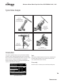
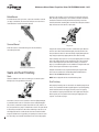
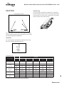
USER INSTRUCTIONS
Edward Valves
Edward Forged Steel Valves, Bolted and Screwed Bonnet Types
FCD EVENIM2001-04-AQ – 10/15 (Replaces V-376 R3)
Experience In Motion
Installation
Operation
Maintenance
Maintenance Manual Edward Forged Steel Valves FCD EVENIM2001-04-AQ – 10/15
Contents
Typical Valves Designs
3
Introduction3
Seat and Set Finishing
4
Disks and Disk Tack Welds
5
Backseat and Packings
6
Gland Bolts
7
Reassembly8
General Information
9
2
Maintenance Manual Edward Forged Steel Valves FCD EVENIM2001-04-AQ – 10/15
Typical Valve Designs
Figure 158
Screwed Bonnet Stop,
Screwed Gland, Inside
Screw, Screwed-in Seat
Figure 1048Y
Bolted Bonnet
Stop, Bolted Gland,
O.S.& Y
Figure 1443
ANGLE BLOW-OFF
VALVE
Figure 1441
STRAIGHTWAY
BLOW-OFF VALVE
Figure 838
Bolted Cover Piston Check
Bolted Bonnet, Bolted Gland, O.S.& Y
Introduction
This manual is provided to help you service your Flowserve-Edward
Forged Steel valves. Before disassembling any valve, we recommend
that you check the valve identification plate and note size, figure number
and pressure class, so that you can identify it in the appropriate Flowserve-Edward Valve catalog. This catalog will show typical cross
sections to help identify the various parts.
Tools
Most Flowserve-Edward Forged Steel valves may be readily disassembled with ordinary hand tools. For the removal of screwed-in valve
seats, a special wrench may be necessary.
Disassembly
Confirm the valve is not under pressure when disassembling valves.
3
Typical Identification Plates
flowserve.com
Maintenance Manual Edward Forged Steel Valves FCD EVENIM2001-04-AQ – 10/15
Bolted Bonnet
In bolted bonnet/ cover style valves, cap screws should be removed
(see page 3 and below). The bonnet assembly or cover can then be
removed and the interior of the valve exposed.
which the seat shoulder rests is clean and true to provide a tight seal.
New “ O”Rings should always be used. Surfaces should be blued and
checked for contact all the way around when replacing a seat. Care
should be taken that reworking does not throw the sealing face between
body and seat out of line with the seat threads.
Figure 238 - Bolted Cover Strainer
Screwed Bonnet
Integral Seat
Small valves of the screwed bonnet type are disassembled by unscrewing the bonnet.
Screwed Bonnet Construction
Seats and Seat Finishing
Seats
Flowserve-Edward valve seats are of two types: screwed-in (with “
O”Ring Seal) or integral with the valve body.
Integral valve seating surfaces cannot be removed for repair. Once the
valve has been disassembled and thoroughly cleaned, determine the
best procedure based on the extent of damage. Lightly damaged seats
may simply be repaired by lapping with the valve disk assembly.
Heavier damage may require the use of special lapping tools or removal
of the valve body from the line for remachining. These valves should
then be finish-lapped using the valve disk assembly (see sketch on
page 5). Seat refinishing tools are also available for integral Stellite seat
valves. Consult your local Flowserve representative.
Complete instructions for the repair and finishing of integral Stellite
valve seats are contained in “Univalve Operation and Maintenance
Manual” FCD EVENIM2000 (Bulletin V-370).
NOTE: Refer to Appendix for list of Seat Refinishing Tools.
Seat Finishing
After properly installing seats in valve bodies or reworking integral seat
valves, the seat and disk should be lapped together. To preclude galling,
caution should be taken not to apply too much pressure in lapping
seats and disks. Lapping should be done with a light load, lifting the
disk frequently to a new position and cleaning the lapping faces as
required. See sketch on page 5.
4
Screwed-in seats can best be repaired, if more than lightly damaged,
by removal from the valve. If screwed-in seats are badly damaged, it
may be more economical to replace them with new seats; however, if
they are repairable, they may be remachined on a lathe. The part should
be accurately centered in the lathe before machining. Seats can be cut
with highspeed tool bits. Stellite-faced seats must be machined with
tungsten-carbide tools or by grinding. In replacing a screwed-in seat in
the valve body, care should be taken that the face on the body against
Maintenance Manual Edward Forged Steel Valves FCD EVENIM2001-04-AQ – 10/15
Stellite Wire Construction
Lapping with Lap or Abrasive Disk
Stop-Check valve disks are not attached to the stem and respond to the
fluid flow in the same manner as check valve disks (see below). The
disk seating face can be repaired in a similar manner to that described
for seats.
Lapping with Valve Disk Assembly
The effectiveness of valve seat lapping can best be judged by blueing
the disk and rotating it lightly in the seat. A full contact should be obtained around the circumference of the seat. A valve that shows this
full contact should be pressure tight after assembly when proper stem
load is applied.
Disks and Disk Tack Welds
Disks
In all Flowserve-Edward valves, disks are designed to swivel on the
valve stem. They are held in place by either a “T”-slot connection, a disk
nut, or Stellite wire.
T-slot Construction
Figure 846: Typical Stop-Check Valve with Body-Guided Disk
Valve stems are normally provided with a radius at the disk contact
to give center loading. If foreign material gets between this spherical
surface and the disk, or if galling occurs, it may not be possible to close
the valve tightly. In a leaking valve this contact should be checked, if
possible, to be sure it is in proper condition.
Disk Tack Welds
In body-guided valve disks with disk nuts, the disk nut is secured to
the disk by a small weld through the side of the disk, fusing the disk
nut threads and preventing loosening of the disk assembly in service.
Such disks can easily be disassembled if required by drilling out the
fused material at the bottom of the small hole in the disk. The disk nut
can then be unscrewed for servicing. Care must be taken not to drill
through the disk nut wall or the stem may be damaged. When repairs
are complete, the parts can be reassembled with care being taken to
screw the disk nut down until only a few thousandths of an inch in end
play remain in the assembly. The parts can then be lock-welded again
by depositing weld metal at the bottom of the small hole in the disk.
Disk Nut Construction
5
flowserve.com
Maintenance Manual Edward Forged Steel Valves FCD EVENIM2001-04-AQ – 10/15
Integral Backseat Construction
Figure 838: Bolted Cover Piston Check
Valves may be body-guided by rings on the disk or in the case of “T”slot disks by the disk outside diameter. A similar body guiding arrangement may be found in check valves. Some ball check valves are guided
by an extension of the cover (see Figure 160). The wear on sliding surfaces inside valves should be considered and the surfaces checked to
be sure wear has not resulted in ridges in the guide bore, which might
impair disk movement. Guiding in check valves is particularly critical.
The guides must be close enough to bring the disk accurately down into
the seat to make a tight joint.
Packings
Flowserve-Edward valves are packed with all-purpose packing sets. This
is a combination of packing using braided rings at the top and bottom
of the packing chamber and flexible graphite packing in the center
section. Packing glands should be tightened down enough to prevent
leakage but not enough to develop excessive operating torque.
When the gland has advanced approximately half way into the packing
chamber, it is recommended that additional packing rings be added. To
obtain best results, the stem should be thoroughly cleaned.
Replacement packing should be the same as that originally furnished.
Flowserve-Edward valve packings are inhibited to prevent stem pitting
in service.
We recommend packing be purchased from Flowserve-Raleigh to assure
packing with the proper density and corrosion inhibitors is always used.
IMPORTANT!
Figure 160: Screwed-Cover, Cover-guided Ball Check, Screwed-in Set
Foreign material in the flow medium may wedge between guiding surfaces with the possibility of making the disk stick. It is recommended
that piston check valves be used where the fluids are clean and where
tight seating is important. In smaller sizes, it is recommended that
ball type check valves be used where the problem of sticking open is
of serious consideration. Valves sized too large for flow condition will
sometimes have excessive wear, chatter and noise.
6
•
Long service life from modern graphitic packing requires that
adequate preloads be applied when repacking.
•
All parts should be clean and not scored or pitted, especially the stem.
•
The stem, disk and bonnet should be in the valve prior to installing
the new packing.
•
Position split packing with the ends of adjacent rings rotated 90°.
•
Standard packing
Top Ring
Braided Ring
Center Ring Flexible Graphite Ring
Bottom Ring Same as top
Backseat and Packings
•
Clean and lubricate the gland bolts.
Backseat
•
Tamp the packing down by hand using the gland.
Flowserve-Edward stop valves have a backseat integral with the bonnet.
The seating face on the bonnet is generally a bevel and the seating
surface on the disk, disk nut, or stem is provided with either a radius or
a bevel. Care must be taken of sealing surfaces on both the bonnet and
the radius, which seals against it to obtain a tight backseat.
•
IMPORTANT! Apply the recommended torque to the gland nuts
evenly without cocking the gland. See table.
•
Tighten nuts to the initial values shown, then loosen and retighten
to the final range.
•
Stroke the stem and then recheck the torque on the gland bolts.
Maintenance Manual Edward Forged Steel Valves FCD EVENIM2001-04-AQ – 10/15
Gland Bolts
Yoke Bushing
The yoke bushings of small Flowserve-Edward valves are threaded to
the yoke. Bushings are subject to wear in services where large amounts
of grit accumulate on the valve threads. Lubrication aids easy operation
of valves and reduces wear of yoke bushings.
Packing Chamber Schematic
FLEXIBLE
GRAPHITE
RING
BRAIDED
RIN GS (2)
Valves of the Figure 158 , 5158 , 9158 (see pg. 3) type have a packing
nut with threads that should be kept well lubricated to prevent corrosion
and eliminate packing adjustment difficulties.
Gland Bolts
The removal of glands is accomplished by removing the nuts. Swing
bolts can be removed by also driving out the pin.
Swing Type
Packing Gland Torque
VALVE SIZE
FIGURE NUMBERS
1/ 4, 3 / 8
1/2
3/4
1
1-1/4
1-1/2
2
final
125-130 FT-LB
140-145 FT-LB
265-270 FT-LB
280-285 FT-LB
435-440 FT-LB
828 ,829
847 ,848
849 ,868 ,869
initial
21
40
62
153
210
final
8-18
15-25
24-34
59-69
81-91
1029 ,1047
1048 ,1068
1069
initial
21
40
62
153
210
final
15-25
28-38
43-53
106-116
145-155
1441 ,1443
1641 ,1643
initial
250
287
71-81
82-92
1028
1046
initial
40
62
62
153
210
final
28-38
43-53
43-53
106-116
145-155
158
5158 ,9158
final
7
ALL TORQUES ARE GIVEN IN INCH-POUNDS EXCEPT WHERE NOTED
flowserve.com
Maintenance Manual Edward Forged Steel Valves FCD EVENIM2001-04-AQ – 10/15
Reassembly
Valves of the screwed bonnet/ cover type construction are sealed at the
bonnet by flat, soft metal gaskets and “O” Rings. Screwed-in seats are
also sealed by “O” Rings. Such seals require smooth clean surfaces on
body, bonnet or seat. Bolted bonnet valves, such as Figure 848 type,
are sealed with spiral-wound gaskets. In all valves, new gaskets (and
“O” Rings) are recommended for reassembly. Bonnet gaskets (and “O”
Rings) are inexpensive and available out of factory stock.
Valves with screwed bonnet/ cover joints require the bonnet threads to be
well lubricated and tightened to develop sufficient gasket compression.
Bolted Bonnet/Cover Torques
The following procedure is recommended:
1.
Guard against leakage by having these capscrews tight at all times.
2.
Capscrews should be tightened to the torque shown below.
Bolt diameter, Inches
7 / 16
1/2
9 / 16
5/8
3/4
7/ 8
1
1-1/ 8
1-1/ 4
240
370
585
750
Torque, Ft. Lbs.
18
30
45
68
90
150
Seat Ring & Bonnet/Cover Torques
Bonnet/ Cover
Valve Size
Figure Number
Seat Ring Torque
1/ 4, 3 / 8, 1 / 2
158 ,160
75
3/4
158 ,160
100-120
60
1
158 ,160
240-260
125
1-1/ 4, 1-1/ 2
158 ,160
320-340
150
400-420
300
2
A torque wrench should be used for tightening the bonnet, which is
used to preload the spiral-wound gaskets.
3/8
NOTE: The steps for tightening cover capscrews is for the purpose of
pulling the cover down evenly. If this objective can be achieved without
following this suggested method precisely, then some variation from
this method is permissible.
158,160, 5158,
5160, 9160
Torque
40
Welding Flowserve-Edward Valves into Piping Welding is outside the
scope of this manual, but Flowserve recommends you consult the
appropriate welding procedure in ASME/ ANSI B31, or whatever other
codes apply to your system. When welding Flowserve-Edward valves
into piping, make sure there is no foreign material on the seat joint, then
close the valve tightly to avoid distorting the seats.
After welding, open the valve and flush the line to clean out all foreign
matter.
Lubrication
In order to obtain full service life, valves require periodic lubrication of
the stem threads. Exposed threads should be wiped clean of old grease
and accumulated dirt and fresh lubricant applied. This is most effectively done with the valve in the closed position.
For valves that see frequent operation, such as motor-actuated, the
lubricant should be replenished every three months. If extreme service
conditions dictate, a more frequent relube schedule is recommended.
Motor-actuated valves have a lubricant fitting at the yoke flange.
Step #1
Snug to approximately 10% of full recommended torque. Sequence: 1-2-3
Step #2
Torque to approximately 75% of full recommended torque. Sequence: 4-3-2
Step #3
Torque to full recommended torque. Sequence: 1-2-3-4
8
The recommended lubricant for all stem threads, bonnet, packing nut
and bolt threads is Rykon EP #2, manufactured by the American Oil
Company. This is an extreme pressure, extreme temperature lubricant
of high quality. For valves that are operated infrequently, relubrication
should be at least once a year.
Maintenance Manual Edward Forged Steel Valves FCD EVENIM2001-04-AQ – 10/15
General Information
c WARNING: Flowserve-Edward valves are not provided with a
pressure relief device. A pressure relief device must be provided
elsewhere in the piping system to prevent the piping system pressure from exceeding the maximum rated pressure of the valve.
Piping Support
Piping should be supported sufficiently to preclude excessive end loads
on the valve.
VALVE INSTALLATION GUIDELINES
Except as noted below, Flowserve-Edward stop valves and stop-check
or check valves with springs can be installed in any position. Installed
positions with the valve cover or bonnet below horizontal, where dirt
and scale can accumulate in the valve neck, should be avoided.
For optimum performance, the orientation limits shown in Figures 1 and
2 should be observed even for spring-loaded check valves.
The orientation limits shown in Figures 1 and 2 must not be exceeded
for Flowserve-Edward stop-check valves and check valves without
springs. The limitations given for line inclination and bonnet roll angle
should not be combined.
All check and stop-check valves should be installed with 10 or more
diameters of straight pipe upstream of the valve to minimize flow disturbances. For additional information, refer to the “Technical” section
of the Flowserve-Edward Valves Catalog, Publication FCD EVENCT0001.
Seat and Disk joint leaks
A leak existing between the seat and disk of a closed valve might be
indicated by one of the following: a definite pressure loss in the high
pressure side of the valve; continued flow through an inspection drain
on the low pressure side; or, in hot water or steam lines, a downstream
pipe that remains hot beyond the usual length of time and conductivity
range.
Such a leak may be the result of closing on dirt, scale or other foreign
matter in the line. It may also develop because of the operator’s failure
to close the valve tightly. An increased velocity is imparted to a flow
forced through a very small opening. This increased velocity subsequently gives rise to the “cutting” of both disk and seat, particularly by
particles of line scale or rust in suspension or normal solids in solution.
In spite of the fact that the hard-surfaced material on the seat and disk
is corrosionand erosion-resistant, grooves, pit marks, or other surface
irregularities may be formed on the seat and disk joint surfaces when
the disk is closed against a foreign body on the seat. This sometimes
occurs during the initial start-up of a piping system.
Leakage of steam through a valve that is badly steam-cut has a whistling or sonorous sound. If the valve is only slightly steam-cut, however,
leakage is identified by subdued gurgling or weak popping sounds.
These sounds can be heard through a stethoscope or by placing one
end of a stick against the valve body while holding the other end between the teeth, with hands over the ears.
9
flowserve.com
Maintenance Manual Edward Forged Steel Valves FCD EVENIM2001-04-AQ – 10/15
Notes On Valve Operation
Valves equipped with electric motor actuators have special tags attached, which indicate the correct torque switch setting for the
valve. Exceeding these torque switch settings can cause damage to
the valve. Never use an electric motor actuator to backseat a valve.
This can result in damage to the valve stem and bonnet backseat.
Notes On Valve Maintenance
When replacing the bonnet gaskets, follow the torque requirements
on page 9 closely. Failure to torque the gasket properly will result in
gasket failure. When replacing the valve stem packing, never machine
the packing chamber oversize. This will result in blowout of the
packing.
How To Order Parts
During normal working hours, call 800-225-6989 or 919-832-0525.
To assure the correct parts for your Flowserve-Edward valve, include
the valve size, the figure number, including any prefix and/or suffixes
and, if available, the B/M number. All nuclear valves require the B/M
number to properly identify your valve.
This information is located on the valve nameplate. The nameplate
is attached to a yoke leg via a cable. If the nameplate is inaccessible,
you can use your Flowserve-Edward sales drawing; please include
the drawing number as well.
SERVICE
If you have any further questions on valve repair or part replacement, your Flowserve representative will be happy to assist
you. Flowserve-Edward catalogs are available on request.
10
Flowserve Corporation has established industry leadership in the
design and manufacture of its products. When properly selected, this
Flowserve product is designed to perform its intended function safely
during its useful life.
However, the purchaser or user of Flowserve products should be
aware that Flowserve products might be used in numerous applications under a wide variety of industrial service conditions.
Although Flowserve can (and often does) provide general guidelines, it cannot provide specific data and warnings for all possible
applications. The purchaser/user must therefore assume the ultimate
responsibility for the proper sizing and selection, installation, operation, and maintenance of Flowserve products. The purchaser/
user should read and understand the Installation Operation Maintenance (IOM) instructions included with the product, and train its
employees and contractors in the safe use of Flowserve products in
connection with the specific application.
While the information and specifications contained in this literature
are believed to be accurate, they are supplied for informative purposes only and should not be considered certified or as a guarantee
of satisfactory results by reliance thereon. Nothing contained herein
is to be construed as a warranty or guarantee, express or implied,
regarding any matter with respect to this product. Because Flowserve
is continually improving and upgrading its product design, the specifications, dimensions and information contained herein are subject to
change without notice. Should any question arise concerning these
provisions, the purchaser/user should contact Flowserve Corporation
at any one of its worldwide operations or offices.
Maintenance Manual Edward Forged Steel Valves FCD EVENIM2001-04-AQ – 10/15
Appendix
Seat Refinishing Tools
848 Valves
Size
Tool Head Assembly
Guide Bushing
Replacement Cutters
No. Of Cutters on
Head Assembly
0.5
876111
169077
Not Repl.
3
0.75
876112
169078
Not Repl.
3
1
876113
169079
876703
3
11/4 - 11/2
876115
169080
876703
5
2
876115
169081
876703
5
1048 Valves
Size
Tool Head Assembly
Guide Bushing
Replacement Cutters
No. Of Cutters on
Head Assembly
0.5
None Available
None Available
N/A
N/A
0.75
876111
169078
Not Repl.
3
1
876112
169082
Not Repl.
3
11/4 - 11/2
876114
169083
876703
5
2
876115
169084
876703
5
Complete instructions for the repair and finishing of integral Stellite valve seats using the above seat refinishing tools are contained in Service Manual for Edward Univalves FCD EVENIM2000 (Bulletin V-370).
11
flowserve.com
Flowserve Flow Control Division
Edward Valves
1900 South Saunders Street
Raleigh, NC 27603
USA
FCD EVENIM2001-04-AQ 10/15 Printed in USA. (Replaces V-376 R2)
To find your local Flowserve representative
or for more information about Flowserve Corporation, visit
www.flowserve.com.
Flowserve Corporation has established industry leadership in the design and manufacture of its products. When properly selected, this Flowserve product is designed to perform its intended
function safely during its useful life. However, the purchaser or user of Flowserve products should be aware that Flowserve products might be used in numerous applications under a wide
variety of industrial service conditions. Although Flowserve can (and often does) provide general guidelines, it cannot provide specific data and warnings for all possible applications. The purchaser/user must therefore assume the ultimate responsibility for the proper sizing and selection, installation, operation, and maintenance of Flowserve products. The purchaser/user should
read and understand the Installation Operation Maintenance (IOM) instructions included with the product, and train its employees and contractors in the safe use of Flowserve products in
connection with the specific application.
While the information and specifications contained in this literature are believed to be accurate, they are supplied for informative purposes only and should not be considered certified or as
a guarantee of satisfactory results by reliance thereon. Nothing contained herein is to be construed as a warranty or guarantee, express or implied, regarding any matter with respect to this
product. Because Flowserve is continually improving and upgrading its product design, the specifications, dimensions and information contained herein are subject to change without notice.
Should any question arise concerning these provisions, the purchaser/user should contact Flowserve Corporation at any one of its worldwide operations or offices.
© 2015 Flowserve Corporation, Irving, Texas, USA. Flowserve is a registered trademark of Flowserve Corporation.
flowserve.com


![United StiltBS Patent [19] [11] Patent Number: 5,025,556](http://vs1.manualzilla.com/store/data/006008181_1-2c5f49b6565f7d3a6ea1501cb683eb1f-150x150.png)