1
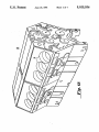
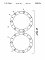
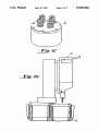
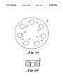
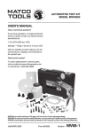
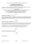
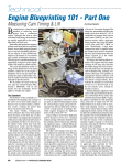
Q
United StiltBS Patent [19]
[11] Patent Number:
Stafford
[45]
[54]
ENGINE BLOCK CYLINDER HEAD BOLT
4,580,931
HOLE REPAIR
4,625,465 12/1986
Date of Patent:
5,025,556
Jun. 25, 1991
4/1986 Wilger et al. ................. .. 408/709 X
Kirt ............. ..
4,652,186 3/1987 Sverdlin
[75]
Inventor:
.
James C. Stafford, Aston, Pa.
.
[73]
Asstgnee:
The United States of America as
4,850,756
4,820,089 4/1989
7 1989 D
Shiets
b
.......................... ,. 40
/
represented by the Secretary of the
Navy, Washington, DC,
'
Bechtel’ sum
.
E. V
‘2;:
57
Filed:
708 X
8/
Primary Examiner-Irene Cuda
Attorney, Agent, or Firm-James V. Tura; James B.
[211 Appl. No.: 554,756
[22]
“ ‘"8 v
Jul. 19, 1990
l
Cr
IRA
1
. .
.
.
A method for repamng cylinder head bolt holes mclud
[52]
Int. CLS .............................................. ..
U.S. Cl. .......................... .. 29/888.011; 29/ 888.06;
removing the Cylinder head from the damaged Cy]
inder bore and removing an adjacent cylinder head
29/402136; 29/40208; 29/402-11; 29/4O2-18;
408/79
from its adjacent cylinder bore. A drill base support is
installed in the adjacent cylinder bore and drilling plat
_
[58]
Fleld of Search .................... .. 29/ 888.011, 888.06,
form Studs are installed at locations corresponding to
[56]
29/402136’ 40208’ 402-04’ 402-05’ 402-11’
4Q2-18; 408/709’ 88’ 95’ 237’ 79; 409/190’ 205’
206
References Cited
the drill base stud holes. A drill base and a jig are in
stalled and a drill press is used to drill and remove bro
ken bolts. The inside diameter of the damaged bolt hole
is measured and studs are installed in the block with
adhesive applied to the threads of the studs.
U.S. PATENT DOCUMENTS
4,234,275 11/1980 Clement ........................ .. 408/709 X
19 Claims, 7 Drawing Sheets
,l5
__
HT!
' l
'?'l
I |
I
L
t,
/‘
n I
\/
I 0
I I
' '
Q |
US. Patent
June 25, 1991
Sheet 2 of 7
5,025,556
US. Patent
June 25, 1991
5,025,556
Sheet 3 of 7
l5
.10
US. Patent
June 25,1991
Sheet 4 of 7 I
5,025,556
Q
US. Patent
June 25, 1991
Sheet 5 of 7
5,025,556
US. Patent
June 25, 1991
Sheet 6 of 7
5,025,556
60
w_
Z
Y/ 4mu/?,/
/ J.
/—1/ /
—
f/IlVf)f
RA
/4K)dAf1,
75
US. Patent
June 25, 1991
Sheet 7 of 7
5,025,556
7/92
W/Jr
,r/v v ,:/v
Pi . IIA
Pi . l/B
1
5,025,556
2
FIG. 2 shows a drill base jig support ring for use in
repairing the engine block cylinder head bolt hole of
ENGINE BLOCK CYLINDER HEAD BOLT HOLE
REPAIR
FIG. 1.
~
FIG. 3 shows a drilling platform stud for use in re
pairing the engine block cylinder head bolt hole of FIG.
STATEMENT OF GOVERNMENT INTEREST
The invention described herein may be manufactured
and used by or for the Government of the United States
of America for governmental purposes without the
payment of any royalties thereon or therefor.
1
FIGS. 4A, B show a drill base jig for use in repairing
the engine block cylinder head bolt hole of FIG. 1.
FIGS. 5A, B show a head jig for use in repairing the
engine block cylinder head bolt hole of FIG. 1.
FIG. 6 shows pilot guide bushings for use in repairing
the engine block cylinder head bolt hole of FIG. 1.
BACKGROUND OF THE INVENTION
1. Field of the Invention
This invention relates to the repair of engine block
cylinder head bolts and engine block cylinder head bolt
holes and in particular to the repair of cylinder head
FIGS. 7A, B show further pilot guide bushings for
use in repairing the engine block cylinder head bolt hole
15 of FIG. 1
FIG. 8 shows an oversized stud for use in repairing
bolts and bolt holes in a large diesel engine block.
2. Prior Art
When engine block cylinder head bolts or engine
the engine block cylinder head bolt hole of FIG. 1.
FIG. 9 shows an internally threaded plug for use in
repairing the engine block cylinder head bolt hole of
block cylinder head bolt holes for large engines such 20 FIG. 1.
has the DCC l6V-l49 engine require repair, the cost
FIG. 10 shows a plug stud for use in repairing the
can be extremely high. Since no effective procedure
engine block cylinder head bolt hole of FIG. 1.
was known, several methods were tried in the prior art.
FIGS. 11A, B show tap guide bushing for use in
These methods sometimes resulted in further damage to
repairing the engine block cylinder head bolt hole of
the engines. In some cases the further damaged engines 25 FIG. 1.
required replacement.
DETAILED DESCRIPTION OF THE
Additionally, because of the extreme heat and stress
on engine block cylinder head bolts and holes, it was
not possible to reliably prevent a future failure. For
-
Referring now to FIGS. 1A, B, 1C and D there is
shown engine block 18 having drill 15 attached thereto,
damaged engine block cylinder 14 and engine block
cylinder head 12. Each cylinder 14 is provided with a
plurality of bolt holes 16 for securing cylinder head 12.
example, if the threads of a block were stripped, a hole
could be redrilled and plugged. However, there is not
very much material in the block and it was impossible to
get the kinds of tolerances needed to perform the opera
Referring now to FIGS. 2-11, there are shown tools
tion effectively enough to prevent another failure. In
addition to the extremely tight tolerances that would
useful for performing the repairs of the method of the
present inventions. Drill base jig support ring 20 may be
formed of aluminum and may be used in cylinder block
have been required to prevent a new failure, almost
perfect alignment is required to prevent a new failure. A
method of obtaining this kind of tolerance was not
known in the prior art.
The object of the present invention is to provide an
easier and more economical way to repair engine block
18 with or without a cylinder liner (not shown). Dril
ling platform stud 24 is required for the drilling of en
gine block cylinder head 12. Drilling platform stud 24
may be formed of grade eight steel. Drill base jig 28 is
provided with a plurality of spaced apart holes 30 ar
cylinder head bolt holes for large engines.
ranged in a circle. Three holes 30 are counterbored
?fteen sixteenths of an inch in diameter by one and
SUMMARY OF THE INVENTION
The method for repairing cylinder head bolt holes
includes removing the cylinder head from the damaged
cylinder bore and removing an adjacent cylinder head
from its adjacent cylinder bore. A drill base support is
installed coupled to the adjacent cylinder bore and
INVENTION
45
one-half inches deep. All projections on the top of cyl
inder head 12 are removed.
Pilot guide bushing 50 is provided with an axial pas
sageway 52 through the entire length of pilot guide
50
bushing 50. Additionally, at the end of the shank of
bushing 50 a shoulder is provided in order to permit
drilling platform studs are installed at locations corre
pilot guide bushing 50 to be seated properly. Pilot guide
sponding to the drill base stud holes. A drill base and a
bushing 50 may be approximately six-eighths of an inch
jig are installed and a drill press is used to drill and
in diameter and approximately ?ve inches in length and
remove broken bolts. The inside diameter of the dam
may be formed of brass. Oversized stud 70 is formed
aged bolt hole is measured and if necessary studs are 55 with a shaft having a block end 72 which may be ap
installed in the block with adhesive applied to the
proximately one and ?ve-eighths inches in length.
threads of the studs.
Oversized stud 70 may be formed of grade eight carbon
steel and may have an overall length of seven and fif
BRIEF DESCRIPTION OF THE DRAWINGS
teen sixteenths inches.
FIG. 1A shows an engine block of an engine suitable 60
Cylinder head 12 is removed from damaged cylinder
for repair in accordance with the method of the present
bore 14. Additionally, an adjacent cylinder head is re
invention.
'
moved from its cylinder bore 13. In the method of the
FIG. 1B shows a plan view of a portion of the engine
present invention cylinder heads 12 are removed and
block of FIG. 1A.
installed in a conventional manner as set forth in DDC
FIG. 1C shows a perspective view of a cylinder head 65 Service Manual (68E 313) for series 149 engines. Bro
of the engine of FIG. 1A.
ken or seized head bolts are removed from cylinder
FIG. 1D shows a view of a drill attached to the cylin
block 18 in accordance with the method of the present
der head of FIG. 1A.
invention as follows. Drill base support 20 is installed in
3
5,025,556
4
cylinder bore 13 adjacent to damaged cylinder bore 14.
depth of two and two-tenths inches, measured from the
Four drilling platform studs 24 are installed at locations
corresponding to drill base stud holes 30. Drill base jig
26 is installed and secured with ?atwashers and nuts.
Drilling platform studs 24 must be below the top surface
of drill base jig 28.
Head jig 40 acts as a template and is installed in a
top of the cylinder liner pilot bore seating surface
manner to locate ?ve-eights inch ream hole 47 over a
broken head bolt. Head jig 40 may be a portion of an
other engine similar to the engine being repaired. Head
jig 40 is secured with cylinder head bolts in hold down
bolt holes 41, 43, 48 wherein hold down bolt 43 is pro
vided with anti-rotation pin 44.
One eighth~inch pilot guide bushing 50 is then in
stalled in ?ve-eighths inch diameter ream hole 47 to
should not be exceeded.
Head jig 40 is then rotated to locate ?ve eighth inch
- é UNF tapped hole 46 over the 37/ 64 inch hole. Head
jig 40 is secured with head bolts. Using a ?ve-eighths
inch-i UNF tap set (not shown), a line tap through head
jig 40 is performed beginning with a starter tap. Chips
should be broken off and cleaned out of damaged hole
16 frequently. A second tap and ?nally a bottom tap
follow the starter tap. Head jig 40 is removed and the
hole and oversized stud 70 are cleaned with a degreas
ing solvent.
Oversized studs 70 should not protrude above the top
surface of cylinder block 18 by more than seven-eighths
inch or less than three-quarters inch. Oversized studs 70
may be remachined at stud block end 72 to adjust the
height of studs 70. After ?tting oversized studs 70, over
a one-eighth inch drill bit to align the drill press with
sized studs 70 are prepared for installation into cylinder
pilot guide bushing 50. The magnetic base drill press is
block 18. Block end 72 threads of studs 70 are sprayed
then locked into position. Using the one-eighth drill bit,
with a primer. Additionally, the threads of the damaged
the broken bolt is drilled out. A drilling depth of two
bolt hole are sprayed with a primer. The primer is al
and one-tenth inches from the top of the cylinder liner
lowed to dry for at least ?ve minutes. When the primer
pilot bore seating surface should not be exceeded. Metal
is dried an even lengthwise bead of an adhesive is ap
drilling chips should be cleaned out of the damaged
hole after each drilling process. The damaged hole 25 plied to the threads of cylinder block 18 and oversized
studs 70. Oversized studs 70 are then inserted into the
should also be blown out with compressed air.
cylinder block head bolt hole. The insertion should be
One-eighth inch pilot guide bushing 50 is then re
done with a continuous rotating motion which should
moved and replaced with three-eights inch pilot guide
continue until oversized stud 70 is completely seated in
bushing 60a. The broken head bolt is then drilled with a,
guide a tap drill (not shown). A magnetic base drill
press (not shown) is mounted on drill base jig 28 using
three-eighths inch drill bit by way of pilot guide bush
ing 600. Head jig 40 may then be removed and the
broken head bolt may be removed with a conventional
cylinder block 18. If the installation of oversized stud 70
is disturbed, oversized stud 70 is immediately removed
and blot hole 16 and oversized stud 70 are degreased
remover. If the broken head bolt still cannot be re
with a solvent. If necessary oversized stud 70 is rema
chined before attempting another insertion into the
moved with a conventional remover, jig head 40 is
replaced in the same location as previously described 35 damaged bolt hole.
After insertion of oversized stud 70 into the damaged
and 33/64 inch pilot guide bushing 60b is inserted. The
bolt hole 16, the adhesive on oversized stud 70 must
broken bolt is then drilled with a 33/64 inch drill bit by
cure for a minimum of twelve hours. After the adhesive
way of pilot guide bushing 60b. Jig head 40 is removed
and the remaining material is tapped out with a conven
has cured, cylinder head components and cylinder head
tional starter tap.
40 12 are installed into cylinder block bore 14 and head
The drilled cylinder hole is cleaned out and the ?t of
bolts and studs are torqued, in three equal steps, to
approximately one hundred and ?fty foot pounds. '
a new head bolt to the tapped hole is determined. If the
new head bolt does not hold one hundred ?fty foot
Oversized studs 70 are torqued last.
pounds with cylinder head 12 in place, additional repair
Twelve hours after the torquing of head bolts and
of the damaged cylinder bolt hole is necessary, includ
oversized studs 70, the torque of cylinder head over
ing the installation of oversized stud 70.
sized studs 70 are checked. The minimum torque should
be one hundred forty foot pounds. If the torque does not
The inside diameter of the damaged bolt hole is mea
hold after a second check on oversized studs 70,
sured with a telescoping gauge (not shown) and an
inside micrometer (not shown). If any measurement of
the upper ?fty percent of the threaded area exceeds 0.58
threaded plug 80 is installed.
inches or if thirty percent of the total area exceeds 0.58
necessary for the repair using the method of the present
invention. Cylinder head 12 is removed from damaged
cylinder bore 14 and the adjacent cylinder head is re
moved from the adjacent cylinder bore 13. Oversized
inches, the damaged cylinder hole must be plugged.
However, if the dimensions of the damaged bolt hole
are within speci?cation, oversized studs 70 are ma
chined in the quantity required for the repair. Cylinder
Threaded plugs 80 and plug ,studs 90 are machined as
head 12 is removed from damaged cylinder bore 14 and
studs 70 to be replaced are removed and drill base sup
port 20 with drilling platform studs 24 are installed.
the adjacent cylinder head is removed from adjacent
Drill base 28 is again installed. Five eighths-inch
cylinder bore 13 as previously described. Drill base
reamed hole 47 is disposed above bolt hole 16 to be
support rig 20 and drilling platform studs 24 are also
plugged and the magnetic base drill press is again set up
installed so that drill base jig 23 may be again secured. 60 on drill base jig 28. The drill press is aligned with the
Head jig 40 is installed with 37/64 inch ream hole 42
?ve-eights ream hole using a ?ve-eights inch drill bit.
is disposed over the damaged bolt hole to be drilled and
The magnetic base is locked into position. The damaged
tapped for oversized studs 70. A magnetic base drill
cylinder bolt hole is then drilled using a ?ve-eighth inch
drill bit. A drilling depth of two and two-tenths inches,
press (not shown) is installed on drill base jig 28. The
magnetic base drill press is aligned with 37/64 inch 65 measured from the top of the cylinder liner pilot bore
reamed hole 42 using a 37/64 inch drill bit. The mag
seating surface should not be exceeded.
netic base is locked into position. Using the 37/64 inch
Head jig 40 is rotated to locate eleven-sixteenths inch
drill bit damage cylinder hole 16 is drilled. A drilling
16 UNF tapped hole ~45 over the drilled ?ve-eighths
5,025,556
.
6
5
ing plug studs 90 last. After a twelve hour period, a
inch hole. Head jig 40 is then secured with head bolts
21. Using a 11/16-16 inch UNF tap set (not shown), the
determination of the torque of cylinder head oversized
studs 70 is made. The minimum torque should be one
line tap is performed through head jig 4-0 as previously
described. Head jig 40 is removed and, along with
threaded plug 80, cleaned with a degreasing solvent.
When threaded plug 80 ?ts the cylinder bolt hole, the
external threads of threaded plug 80 are sprayed with a
primer and the primer is allowed to dry for ?ve minutes.
hundred forty foot pounds.
Thus the method and precision special tools of the
present invention provide an effective means for remov
ing broken cylinder head bolts and repairing damaged ~
cylinder head bolt holes wherein a drilling platform and
an alignment ?xture are installed in adjacent cylinders
When the primer has dried for ?ve minutes, an even
lengthwise bead of adhesive is applied to the threads on
of the engine being repaired. The platform and ?xtures
provide precision alignment for the drilling processes
the exterior of threaded plug 80 only.
Threaded plug 80 is installed into the eleven-six
teenths inch tapped cylinder block head bolt hole. A
continuous rotating motion must be used and the instal
lation of threaded plug 80 should not stop until threaded
plug 80 is completely seated in cylinder block 18. If
continuous rotating advancement of threaded plug 80
ceases before seating of threaded plug 80, threaded plug
80 can be removed by redrilling. If threaded plug 80 is
installed with a one-eighth inch pilot hole, only head jig
40 is installed so that ?ve-eighths inch reamed hole 46 is
disposed over the plugged hole. One-eighth inch pilot
which allows for the removal of the broken bolts and
reliable repair of the engine. The same platform and
?xture are then utilized to repair damaged cylinder
head bolt holes by rotating the drill ?xture to the func
tion required as described by the methods provided
allowing for the installation of replacement studs or
inserted plugs attached with adhesive applied to the
threads. The drill ?xture may be a removed part of an
engine similar to the engine being repaired in order to
assure precise alignment. Due to the very precise toler
ances and alignment made possible by rigidly ?xing the
drill to the engine it is possible to make repairs which
guide bushing 50 is installed into the ream hole and the
magnetic base drill press is set up on drill base jig 28.
The drill press with a one-eighth drill bit is aligned with
the one-eighth inch drill bushing and the one eighth
pilot hole in plug 80. The magnetic base is locked into
. position and head jig 40 is secured with head bolts 21.
One-eighth inch pilot guide bushing 50 is removed
and replaced with guide bushing 60a. Threaded plug 80
is drilled to a depth of one and one-quarter inches as
measured from the top of plug 80. Guide bushing 60a is
removed and replaced with guide bushing 60b and
threaded plug 80 is drilled using a 33/64 inch drill bit.
Head jig 40 is rotated to locate seven-eighths inch diam
eter reamed hole 43 over drilled out threaded plug 80.
Nine-sixteenths inch tap guide bushing 100 is installed
into ream hole 43 on one-quarter inch diameter anti
rotation end 44. Guide bushing 60b is aligned with
threaded plug 80 using a 33/64 inch drill bit. When
withstand the severe stress caused by usage of the re
paired engine.
The method of the present invention may be repeated
as necessary to complete the repair of any number of
damaged or broken cylinder head bolts or any number
of cylinder head bolt holes 16.
It will be understood that various changes in the
details, materials and arrangements of the parts which
have been described and illustrated in order to explain
the nature of this invention, may be made by those
skilled in the art without departing from the principle
and scope of the invention as expressed in the following
claims.
What is claimed is:
1. A method for repairing a damaged engine block
cylinder head bolt and a damaged engine block cylinder
40 head bolt hole in a large engine for powering a large
bushing 60b is aligned, head jig 40 is secured with head
bolts. Using a nine-sixteenths inch 18 UNF tap set, a line
tap to threaded plug 80 is performed through bushing
vehicle of said engine requiring high precision toler
ances and high precision alignment, said engine having
a plurality of engine block cylinders, each cylinder
having a plurality of engine block cylinders bolt holes,
Head jig 40 is removed and threaded plug 80 and plug 45 comprising the steps of:
(a) rigidly ?xing drill support means to said engine,
stud 90 are cleaned with a degreasing solvent. Plug stud
(b) rigidly ?xing drill means to said drill support
90 should not extend above the top surface of cylinder
60b.
block 18 more than seven-eighths inch or less than
threequarters inch. If the speci?cations are not met,
plug stud 90 is remachined. Plug hole 16 and plug stud 50
90 are then cleaned. If threaded plug 80 is installed with
internal nine-sixteenth-IS UNF threads already ma
chined, the repair method proceeds to this point with
out the last use of the magnetic base drill press.
Block end 92 of plug stud 90, as well as the internal
threads of plug 80, are sprayed with a primer. The
primer is allowed to dry for ?ve minutes. After the ?ve
minute period, an even lengthwise bead of adhesive is
applied to the block end threads of plug stud 90. Plug
means,
(c) rigidly coupling said drill support means to a fur
ther engine block cylinder head bolt hole in the
vicinity of said damaged bolt hole, and
(d) drilling said damaged engine block cylinder head
bolt hole with high precision tolerances and high
precision alignment by means of said rigidly ?xed
drill while said engine is disposed in said vehicle.
2. The method of claim 1, wherein step (c) is followed
by the further step of drilling a damaged bolt within said
damaged engine block cylinder head bolt hole.
3. The method of claim 1, comprising the further step
stud 90 is then inserted into the cylinder block head 60 of inserting oversized stud means into said drilled en
gine block cylinder head bolt hole.
plugged bolt hole. When inserting plug stud 90 a contin
4. The method of claim 3, comprising the further step
uous rotating motion must be used until plug stud 90 is
of machining said oversized stud to precisely ?t said
completely seated in threaded plug 80. The adhesive on
drilled engine block cylinder head bolt hole.
threaded plug 80 and plug stud 90 are allowed to cure
5. The method of claim 3, comprising the further
for a minimum of twelve hours. The cylinder head 65
steps of:
components and cylinder head 12 are installed into
(d) applying adhesive to said oversized stud and said
cylinder block bore 14. The head bolts and oversized
drilled engine block cylinder head bolt hole; and
studs 70 are torqued to one hundred ?fty pounds, torqu
7
5,025,556
8
said damaged engine block cylinder head bolt hole,
(e) curing said adhesive.
6. The method of claim 1', further comprising the step
of positioningsaid drill means by means of a template
adapted to precisely position said drill means over said
and
(d) drilling said damaged engine block cylinder head
bolt hole with high precision tolerances and align
damaged engine block cylinder head bolt hole.
ment by means of said rigidly ?xed drill while said
engine is disposed in said vehicle.
13. The method of claim 12, wherein said template is
7. The method of claim 6, wherein said template is
adjustably rotatable to position drill bits of differing
sizes over a selected one of said plurality of engine
adjustably rotatable to position drill bits of differing
block cylinder head bolt holes.
sizes over a selected one of said plurality of engine
8. The method of claim 7 wherein said template is 10 block cylinder head bolt holes.
formed of a portion of an engine.
14. The method of claim 12, wherein said template is
9. The method of claim 6, further comprising the step
formed of a portion of an engine.
of rotating said template to provide differing template
15. The method of claim 12, further comprising the
holes for said drill means.
step of rotating said template to provide differing tem
10. The method of claim 9, comprising the further
plate holes for said drill means.
steps of:
16. The method of claim 12, comprising the further
(h) drilling said threaded plug; and
steps of:
(i) inserting a plug stud into said drilled threaded
(e) drilling said damaged engine block cylinder head
plug.
11. The method of claim 1, comprising the further 20
steps of:
bolt hole to increase the diameter of said damaged
engine block cylinder head bolt hole; and
(f) inserting a threaded plug into said enlarged diame
(f) drilling said damaged engine block cylinder head
ter engine block cylinder head bolt hole.
bolt hole to increase the diameter of said damaged
17. The method of claim 16, comprising the further
engine block cylinder head bolt hole;
(g) inserting a threaded plug into said enlarged diame 25 steps of:
(g) drilling said threaded plug; and
ter engine block cylinder head bolt hole.
(i) inserting a plug stud into said drilled threaded
12. A method for repairing a damaged engine block
plug.
I cylinder head bolt and a damaged engine block cylinder
18. The method of claim 12, wherein step (c) is fol
lowed
by the further step of drilling a damaged bolt
30
vehicle said engine requiring high precision tolerances
head bolt hole in a large engine for powering a large
within said damaged engine block cylinder head bolt
and high precision alignment, said engine having a plu
rality of engine block cylinders, each cylinder having a
plurality of engine block cylinder head bolt holes, com
prising the steps of:
(a) rigidly fixing drill support means to said engine,
(b) rigidly fixing drill means to said drill support
hole.
19. The method of claim 12, wherein there is pro
vided a further engine block cylinder head bolt hole in
35
the vicinity of said damaged engine block cylinder bolt
hole and step (a) comprises the step of coupling said
drill support means to said further engine block cylinder
head bolt hole.
means,
(c) positioning said drill means by means of a template
adapted to precisely position said drill means over
#
45
55
65
4'
1?
it
t