1
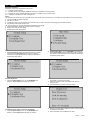
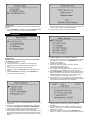
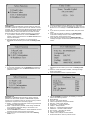
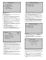
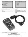
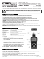
INSTRUCTIONS FOR
VAG CODE READER AND RESET TOOL
EOBD & GENERIC
Model: VS862
Thank you for purchasing a Sealey Product. Manufactured to a high standard this product will, if used according to these instructions and properly
maintained, give you years of trouble free performance.
IMPORTANT: PLEASE READ THESE INSTRUCTIONS CAREFULLY. NOTE THE SAFE OPERATIONAL REQUIREMENTS,
WARNINGS AND CAUTIONS. USE THIS PRODUCT CORRECTLY AND WITH CARE FOR THE PURPOSE FOR WHICH IT IS
INTENDED. FAILURE TO DO SO MAY CAUSE DAMAGE AND/OR PERSONAL INJURY AND WILL INVALIDATE THE
WARRANTY. PLEASE KEEP THESE INSTRUCTIONS SAFE FOR FUTURE USE.
1.
!
"
#
#
#
#
#
!
"
#
#
#
#
SAFETY INSTRUCTIONS
WARNING! Ensure that Health and Safety, local authority and general workshop practice regulations are strictly adhered to.
DO NOT use the unit if it, or any attachment, is damaged.
Maintain the unit in good and clean condition for best and safest performance.
If required, ensure that the vehicle to be worked on is adequately supported with axle stands or ramps and is chocked.
Put transmission in PARK (for automatic transmission) or NEUTRAL (for manual transmission) and make sure the parking brake is engaged.
Wear approved eye protection. A full range of personal safety equipment is available from your Sealey dealer.
Wear suitable clothing to avoid snagging. Do not wear jewellery and tie back long hair.
WARNING! Use extreme caution when working around the ignition coil, distributor cap, ignition wires and spark plugs. These components
create hazardous voltages when the engine is running.
DO NOT connect or disconnect any test equipment with ignition on or engine running.
Keep a fire extinguisher suitable for gasoline/chemical/ electrical fires nearby.
Account for all tools and parts being used and do not leave them on or near the engine.
Keep code reader dry, clean and free from oil, water and grease. Use a mild detergent on a clean cloth to clean the outside of the tool.
Operate the vehicle in a well-ventilated work area; exhaust gases are poisonous.
IMPORTANT: Always refer to the vehicle manufacturer’s service instructions, or a proprietory manual, to establish the current procedure and data.
These instructions are provided as a guide only.
2.
SPECIFICATION & ACCESSORIES
Display:
Operating Temperature:
Storage Temperature:
External Power:
Accessories Included
User's Manual
OBD2 cable
Serial Cable
Carry Case
Backlit, 128 x 64 pixel display with contrast adjustment.
0 to 50°C (32 to 122 F°).
-20 to 70°C (-4 to 158 F°).
8.0 to 15.0 Volts provided via vehicle battery.
Instructions on tool operations.
Provides power to tool and communicates between tool and
vehicle.
Used to upgrade the scan tool.
A nylon case to store the scan tool when not in use.
Fig. 1
Fig. 1 Reference:
1
LCD DISPLAY -- Indicates test results.
2
Y BUTTON -- Confirms a selection (or action) from a menu. When a DTC's
definition covers more than one screen, it is used to move down to the next
screen for additional data.
3
N BUTTON -- Cancels a selection (or action) from a menu or returns to the menu.
It is also used to set up the unit when pressed and held for at least 3 sec.
4
UP SCROLL BUTTON -- Moves up through menu and submenu items in menu
mode. When more than one DTC is retrieved, moves up through the current
screen to the previous screens for additional DTCs and definitions.
5
DOWN SCROLL BUTTON -- Moves down through menu and submenu items in
menu mode. When more than one DTC is retrieved, moves down through the
current screen to the next screens for additional DTCs and definitions.
6
OBD II CONNECTOR -- Connects the scan tool to the vehicle's Data Link
Connector (DLC).
3.
VEHICLE APPLICATIONS
Vehicle Coverage
Audi, Seat, Skoda, VW; Beetle, Golf, GTI, Jetta, Passat, Toureg.
The VS862 Code Reader and Reset Tool is specially designed to work with most VAG vehicles sold Worldwide from 1990 on. If a VAG has a
16-pin RJ1966 Data Link Connector (DLC), the code reader will work.
If it has an old-style 2x2 Data Link Connector (DLC), then it depends on whether there are 4 or 3 wires connecting to the pins.
If there are 4 wires, each connecting a pin, then it will work.
If there are only 3 wires, leaving one pin disconnected, then it will not work.
For VAG with old-style 2x2 Data Link Connector (DLC), you need to have a 2x2 cabling adapter which is not included in this product package.
Part No. VS8X01
VS862 - 1 - 040107
4.
SETUP
Navigation Characters
Characters used to help navigate the scan tool are:
"!" -- Indicates current selection.
"3" -- A flashing Down Arrow indicates additional information is available on the next screen.
"1" -- A flashing UP Arrow indicates additional information is available on the previous screen.
"Pd" -- Identifying a Pending DTC when viewing DTCs.
Power
The external power of the scan tool is provided via the vehicle Data Link Connector (DLC). Just follow the steps below to turn on the scan tool:
1 Connect the OBD II Cable to scan tool.
2 Find DLC on vehicle.
3 A plastic DLC cover may be found for some vehicles and you need to remove it before plugging the RJ1966 connector.
4 Plug RJ1966 Cable to the vehicle's DLC.
The scan tool allows you to make the following adjustments and settings:
1 Contrast adjustment: Adjusts the contrast of the LCD display.
2 Display Test: Tests the LCD display.
3 Keyboard test: Tests the keyboard.
To enter the setup menu mode
1 From the keyboard: Press and hold the N button for at least 3
seconds until the System Setup menu shows. Follow the
instructions to make adjustments and settings as described in
the following setup options.
2
From the Main Menu: Use the UP/DOWN Scroll Buttons to
select System Setup and then press the Y button. Follow the
instructions to make adjustments and settings as described in
the following setup options.
Contrast Adjustment
1 From the System Setup menu, use the UP/DOWN scroll
buttons to select Contrast, and press the Y button.
2
From the Contrast menu, use the UP/DOWN scroll buttons
to decrease or increase the contrast.
Press the Y button to save your selection and return to
previous menu.
Press the N button to return to previous menus.
3
4
Display Test
The Display Test is used to check the LCD display.
1 From the System Setup menu, use the UP/DOWN scroll
buttons to select Display Test and press the Y button.
2
3
Press the Y button again to start test. Look for missing spots in
the solid black characters.
When completed, press the N button to return.
VS862 - 1 - 040107
Keyboard Test
The Keyboard Test is used to verify that the keys are functioning
properly.
1 Use the UP/DOWN scroll buttons to select Keyboard Test from
the System Setup menu, and then press the Y button.
5.
2
3
OPERATION
VAG Diagnostics
Reading Codes
CAUTION: Don't connect or disconnect any test equipment
with ignition on or engine running.
1 Turn the ignition off.
2 Locate the vehicle's 16-pin Data Link Connector (DLC).
3 Plug into the scan tool cable connector to the vehicle's
DLC.
4 Turn the ignition on. But do not start the engine.
5 Press the Y button. The Main Menu will be observed on the
display.
6 Use the UP/DOWN scroll buttons to select VW/AUDI from
the menu and press the Y button.
7
#
#
#
#
!
!
8
Press any key to start test. When you press a key, the key
name should be observed on the display. If the name does not
show up, then the key is not functioning properly.
Double press N to return to the previous menu.
Select Read Codes from the Select Funciton menu and press
the Y button.
! If there are no Diagnostic Trouble Codes present, the display
will indicate "NO CODES ARE STORED IN THE MODULE!"
! If there are any Diagnostic Trouble Codes present, the DTC
number and its definition will show on the LCD display.
! The subcode, the communication protocol, the sequence of the
DTC currently being observed and the total number of codes
detected will be observed on the upper right hand corner of the
display.
Use the UP/DOWN scroll buttons to select the system from
the Select System menu and press the Y button.
If the scan tool fails to communicate with the selected vehicle's
ECU (Electronic Control Unit), a "LINK ERROR!" message
shows up on the display.
Verify that the ignition is ON.
Check if the scan tool's OBD II connector is securely
connected to the vehicle's DLC.
Verify that the module is supported.
Turn the ignition off and wait for about 10 seconds. Turn the
ignition back to on and repeat the procedure from step 5.
If the "LINK ERROR!" message does not go away, then there
might be problems for the scan tool to communicate with the
module being tested. The most common cause is that the
scanned module is not supported on the vehicle.
The numbers (01, 02, 15, 03, 08, etc) in front of the system
names refer to the physcal addresses assigned to the systems,
not the sequence of the systems to be arranged.
! When a DTC's definition covers more than one display screen,
use the Y button, as necessary, to view any additional
information.
! If the DTC definition is not available, an advisory message
prompting you to refer to the vehicle service manual will be
observed on the display.
! If more than one DTC is found, use the UP/DOWN scroll
buttons, as necessary, until all the codes have been shown up.
Erasing Codes
CAUTION: Erasing the Diagnostic Trouble Codes may allow the
scan tool to delete not only the codes from the vehicle's on-board
computer, but also "Freeze Frame" data and manufacturer specific
enhanced data. Further, the I/M Readiness Monitor Status for all
vehicle monitors is reset to Fail status. Do not erase the codes
before the system has been checked completely by a technician.
If you decide to erase the DTCs, use the UP/DOWN scroll
buttons to select Erase Codes from the Select Function menu
and press the Y button.
! If the scan tool is not connected or no communication is
established with the vehicle yet, then refer to Reading Codes
1 to 7.
2
3
4
5
1
6
A warning message comes up asking for your confirmation.
If you do not want to proceed with erasing the codes, press the
N button to exit. A message of "command cancelled" will show
up.
If you do wish to proceed to erase the codes, then press the Y
button.
If the codes are cleared successfully, an "ERASE DONE!"
confirmation message will show on the display. Press any
button to return to the previous menus.
If the codes are not cleared, then an "ERASE FAILURE!"
message will appear. Press the N button to return to previous
menus.
Viewing ECU Information
1 To view ECU Information, use the UP/DOWN scroll buttons to
select ECU Information from the Select Function menu and
press the Y button.
! If the scan tool is not connected or no communication is
established with the vehicle yet, then refer to Reading Codes
1 to 7.
! If there is no ECU Information available, a warning message
shows on the display.
2 Press the N button to return to previous menus.
Readiness Test
Important: The Readiness Test function is used to check the
operations of the Emission System on OBD2/EOBD compliant
vehicles. It is an excellent function to use prior to having a vehicle
inspected for compliance to an emissions program.
! "Pass" -- Indicates that a particular monitor being checked has
completed its diagnostic testing.
! "Fail" -- Indicates that a particular monitor being checked has
not completed its diagnostic testing or the monitor is not
supported on that vehicle.
1 Use the UP/DOWN scroll buttons to select Readiness Test from
the Select Function menu and press the Y button.
! If the scan tool is not connected yet, then refer to Reading
Codes 1 to 7.
2
!
!
!
!
!
!
!
!
!
!
!
Use the UP/DOWN scroll buttons, as necessary, to view the
status of the following monitors:
Misfire Monitor
Fuel Sys.--Fuel System Monitor
CCM--Comprehensive Components Monitor
EGR Sys.-- EGR System Monitor
O2 Sensor(s) -- O2 Sensors Monitor
Catalyst -- Catalyst Monitor
EVAP Sys. -- Evaporative System Monitor
Heated O2 -- O2 Sensor Heater Monitor
Sec Air Inject -- Secondary Air Monitor
A/C -- A/C System Monitor
Catalytic Conv.-Catalytic Convertor Monitor
3
Press the N button to return to previous menus.
OBDII/EOBD Diagnostics
Reading Codes
CAUTION: Don't connect or disconnect any test equipment with
ignition on or engine running.
1 Turn the ignition off.
2 Locate the vehicle's 16-pin Data Link Connector (DLC).
3 Plug into the scan tool cable connector to the vehicle's DLC.
4 Turn the ignition on. But do not start the engine.
5 Press the Y button. The Main Menu will be observed on the
display.
6 Use the UP/DOWN scroll buttons to select OBDII/EOBD from
the menu.
7 Press the Y button. A sequence of messages showing the
OBDII/EOBD protocols will be observed on the display until
the vehicle protocol is detected.
! If the scan tool fails to communicate with the vehicle's ECU
(Engine Control Unit), a "LINK ERROR!" message shows up
on the display.
# Verify that the ignition is ON.
# Check if the scan tool's OBD II connector is securely
connected to the vehicle's DLC.
# Verify that the vehicle is OBDII/EOBD compliant.
# Turn the ignition off and wait for about 10 seconds. Turn the
ignition back to on and repeat the procedure from step 5.
!
8
9
!
!
If the "LINK ERROR" message does not go away, then there
might be problems for the scan tool to communicate with the
vehicle. Contact your local distributor or the manufacturer's
customer service department for assistance.
After the vehicle protocol is displayed on the screen, press any
key or wait about 2 seconds for the OBDII/EOBD Diag menu to
come up.
Use the UP/DOWN scroll buttons to select Read Codes from
the menu and press the Y button.
If there are no Diagnostic Trouble Codes present, the display
will indicate "NO CODES ARE STORED IN THE MODULE!"
If there are any Diagnostic Trouble Codes present, the Fault
Codes and Pending Codes will be reported on the display.
Erasing Codes
1 If you decide to erase the DTCs, use the UP/DOWN scroll
buttons to select Erase Codes from the OBDII/EOBD Diag.
menu and press the Y button.
! If the scan tool is not connected or no communication is
established with the vehicle yet, then refer to Reading Codes
from 1 to 8.
The DTC number will appear on the upper left hand corner and
its definition will show on the body of screen.
! The type of code (Generic or Manufacturer specific), the
vehicle protocol, the sequence of the DTC currently being
observed, the total number of codes detected and the module
ID will be observed on the upper right hand corner of the
display.
! If the code being displayed is a pending code, the Pd icon will
be observed next to the DTC number on the upper right hand
corner of the display.
! When a DTC's definition covers more than one display screen,
use the Y button, as necessary, to view any additional
information.
! If the retrieved DTCs contain any manufacturer specific or
enhanced codes, you will be prompted to refer to the vehicle
service manual to view the DTC
definitions.
10 If more than one DTC is found, use the UP/DOWN scroll
buttons, as necessary, until all the codes have been shown up.
!
2
3
4
5
6
A warning message comes up asking for your confirmation.
If you do not want to proceed with erasing the codes, press the
N button to exit. A message of "command cancelled" will show
up.
If you do wish to proceed to erase the codes, then press the Y
button.
If the codes are cleared successfully, an "ERASE DONE!"
confirmation will show on the display. Press any button to return
to previous menus.
If the codes are not cleared, then an "ERASE FAILURE!"
message will appear. Press the N button to return to previous
menus.
Oil
1
2
3
4
5
6
Reset
Turn the ignition off.
Locate the vehicle's 16-pin Data Link Connector (DLC).
Plug into the scan tool cable connector to the vehicle's DLC.
Turn the ignition on. But do not start the engine.
Press the Y button. The Main Menu will be observed on the
display.
Use the UP/DOWN scroll buttons to select Oil Reset from the
menu. Press the Y button to accept the option and to move to
the next screen.
7
a
Do the following to select menu options:
Use the UP/DOWN scroll buttons to move the cursor (!) and
select an option.
b Press the Y button to accept the option and to move to the
next screen.
c Repeat a and b to select the necessary options.
8 Follow any on-screen instructions. Optionally, use the N button
to return to previous screens.
9 If the Service Reset Failed message appears, then there might
be problems for the scan tool to communicate with the vehicle
being tested. Refer to the vehicle service manual for more
information.
10 When done, turn off the ignition and disconnect the scan tool.
NOTE: It is our policy to continually improve products and as such we reserve the right to alter data, specifications and component parts without prior notice. IMPORTANT: No liability is accepted
for incorrect use of product. WARRANTY: Guarantee is 12 months from purchase date, proof of which will be required for any claim.
INFORMATION: For a copy of our latest catalogue and promotions call us on 01284 757525 and leave your full name and address, including postcode.
JHM Butt & Co Ltd
Sole UK Distributor
01284 719481
757500
Tel: 01302
710868 - Fax: 01302
Sealey Group,
www.jhmbuttco.com
Bury St. Edmunds, Suffolk. - [email protected]
01284 703534
Web
email
www.sealey.co.uk
[email protected]