1
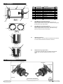
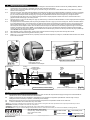
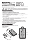
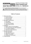
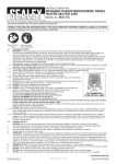
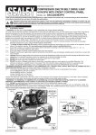
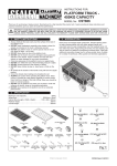
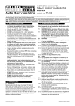
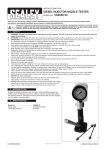
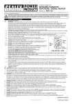
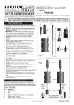
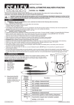
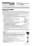
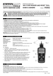
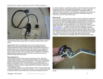
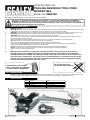
INSTRUCTIONS FOR: TRAILING ARM BUSH TOOL FORD MONDEO Mk4 MODEL No: VSe4784 Thank you for purchasing a Sealey Product. Manufactured to a high standard this product will, if used according to these instructions and properly maintained, give you years of trouble free performance. IMPORTANT: PLEASE READ THESE INSTRUCTIONS CAREFULLY. NOTE THE SAFE OPERATIONAL REQUIREMENTS, WARNINGS AND CAUTIONS. USE THIS PRODUCT CORRECTLY AND WITH CARE FOR THE PURPOSE FOR WHICH IT IS INTENDED. FAILURE TO DO SO MAY CAUSE DAMAGE AND/OR PERSONAL INJURY AND WILL INVALIDATE THE WARRANTY. PLEASE KEEP INSTRUCTIONS SAFE FOR FUTURE USE. 1. SAFETY INSTRUCTIONS 1.1 GENERAL SAFETY IMPORTANT! These instructions are offered as a guide only, albeit compiled with good practical user advice. Always refer to the vehicle manufacturer's service instructions, or a proprietary manual to establish the current procedure and data. WARNING! Ensure Health & Safety, local authority, and general workshop practice regulations are adhered to when using this tool. WARNING! Familiarise yourself with the specific applications and limitations of the kit, as well as any potential hazards. WARNING! This tool is heavy, over 7kg, two people recommended for some tasks. This kit should be used in conjunction with inspection maintenance procedures recommended in the vehicle manufacturer’s manual. Ensure that the kit is correct for the task. Wear the appropriate personal protective equipment for the task. A full range is available from your Sealey dealer. DO NOT use the kit for any purpose other than that for which it is designed. Ensure that the vehicle is properly supported with axle stands before working under the vehicle. Ensure there is adequate lighting prior to using the kit. A range of inspection lamps are available from your Sealey dealer. Keep children and unauthorised persons away from the working area. DO NOT use the kit if any parts are damaged or missing, as this may cause failure and/or personal injury. DO NOT use the kit when you are tired, or under the influence of alcohol, drugs or intoxicating medication. After use, store in a safe, dry childproof area. Warning! Failure to adhere to safety and warning instructions may result in personal injury or damage which would invalidate the warranty. The bush extraction and insertion screw maximum recommended torque is 180Nm. Exceeding this torque value may shorten the life of the thrust screw and distort other components. The thrust screw is considered to be a consumable item and is NOT covered under warranty. Always lubricate the threads male and female with a molybdenum/copper based grease after removing from the carry case. DO NOT USE AIR TOOLS TO OPERATE FORCE SCREW ALWAYS KEEP FORCE SCREW WELL LUBRICATED. MOLYBDENUM COPPER BASED RECOMMENDED. 2.introduction Suitable for the removal/installation of the rear trailing arm mounting bushes on Ford vehicles. Can be used in situ without removing the arm from the vehicle. Also suitable for some Volvo vehicles that share the same Ford platform. Supplied in carry-case. 3. APPLICATIONS Make ModelYear Ford Mk4 Mondeo 2007 - onward Ford S-Max 2006 - onward Ford Galaxy 2006 - onward Volvo S60, S80, XC60, V70, XC70 2006 - onward with Ford Platform Fig.1 Offside Trailing Arm Removed From Vehicle C/W Bush Assembly Bush Assembly (R) Orientation mark see Fig.7 and note 5.1.4 © Jack Sealey Limited Original Language Version VSE4784 Issue No.1 - 01/10/13 4.CONTENTS 7 8 10,11 9 6 Fig.2 10,11 5 3 4 Item Part Number Description Qty 1 VSE4784-01 Adaptor1 2 VSE4784-02 Depth Control Legs 2 3 VSE4784-03 15mm 'C' Ring 1 4 VSE4784-04 35mm 'C' Ring 1 5 VSE4784-05 Press Fame Top Plate 1 6 VSE4784-06 Press Frame Bottom Plate 1 7 VSE4784-07 Distance Studs 2 8 VSE4784-08 Spacer2 9 VSE4784-09 Thrust Screw (M20 X 1.5) 1 10 VSE4784-10 Nut M124 11 VSE4784-11 Plain Washer ø12 4 12 VSE4784-12 M8 X 16 Screw 2 4.1 15mm Magnetic 'C' Ring (Fig.3 item 3) A distance piece used in the bush extraction process only, integral magnets holds the ring in place.The slot in the ring clears the obstruction of the hose bracket. 4.2 35mm Magnetic 'C' Ring (Fig.3 item 4) A distance piece used in the new bush insertion process only, integral magnets holds the ring in place. The slot in the ring clears the obstruction of the hose bracket. Fig.3 1 4.3 Fig.4 Adaptor (Fig.4 item 1) 90mm Diameter x 115 long. Slotted, counterbored and recessed to accommodate extraction and insertion of the bush. 2 12 4.4 Depth Control Legs (Fig.5 item 2) Two Segments nest either side of the adaptor fixed with M8 screws. Only used when inserting new bush to correct depth. 1 Fig.5 5.bush REMOVAL Rivet stud Rivet stud I/D Stamped I/D Stamped R L Nearside Offside Bush Assembly Identification © Jack Sealey Limited Original Language Version Fig.6 VSE4784 Issue No.1 - 01/10/13 5.1NOTE! Illustrations hereafter are with a section of the trailing arm removed from the vehicle and are all "R" (offside) assembly. Refer to manufacturer's service manual, or proprietary manual when using these instructions. 5.1.1 Jack up the vehicle, placing the jack clear of the rear suspension allowing it to swing down. 5.1.2 Support the rear suspension whilst removing the trailing arm bush mounting nuts, bolts and washers. Unclip the handbrake hose and associated fixings. It may be necessary to remove further fastenings to allow the trailing arm to fully sweep beneath the vehicle, enabling maximum access and clearance for the bush extraction tool. Continue supporting the trailing arm and controlling during lowering. 5.1.3 With the area around the suspension now clear we suggest a thorough clean to avoid accumulated debris interferring with precision fitting processes. Spraying a proprietory 'free release' fluid on to the bush sleeve and housing may assist with removal in 5.1.7. 5.1.4 Note the orientation of the existing bush before removal. The method of marking is best decided by the engineer. A scribed line on the bush sleeve><and a mirrored orientation mark on the housing would give an accurate orientation, for example see Fig.7. See also the manufacturer's instructions. 5.1.5 Offer the 15mm 'C' ring on to the pressed steel housing, aligning the gap with the handbrake cable bracket. This will be held in place (Fig.8) by the three permanent magnets inserted in the ring. Ensure it is seated correctly on a grit free face. 5.1.6 Access and adequate clearance is essential for offering the bush press assembly over the trailing arm and bush housing. Weave the bottom plate end over the "Tee" plate (Fig.9) and locate the counterbore with the 'C' ring (Fig.10). Continue to support the opposite end with your hand (Fig.11). It may be necessary to disassemble and reassemble the press frame insitu when access is limited. 5.1.7 Two people are now recommended, with one continuing to support the press frame and the other positioning the adaptor (Fig.12), stepped end inside the bush sleeve. The shoulder of the stepped end will offer thrust to the steel bush sleeve. Please note for the removal of the bush, 360° orientation of the adaptor is not important and the side 'depth control legs' are not fitted. The second person can now wind in the thrust screw ensuring concentricity and squareness of both the press frame and the cylindrical adaptor. With a 16mm socket increase the torque and observe the bush sleeve projection from the housing, through to removal. Excessive torque, above 180NM, is not envisaged, but if this occurs, stop and check alignments. There may be some resistance initially. Continued support to the press is required throughout, especially when the bush is removed from the housing as the bush is then free to fall. Remove the old bush, the press frame and prepare details for insertion of a new bush assembly. An "exploded" view (Fig.13) supports actions shown in (Fig.8) through (Fig.12) Trailing Arm (Fig.1) Press Frame Studs 15mm 'C' ring Fig.8 Locate 'C' ring in counterbore Fig.9 Fig.12 Fig.11 Trailing Arm (Fig.1) Cylindrical Adaptor Old Bush Assembly Removal Details © Jack Sealey Limited Fig.7 Orientation marks Cylindrical ram concentric and square with bush sleeve. NOTE! It may be necessary to disassemble and reassemble the press frame insitu when access is limited. A 17mm spanner only required, the clear opening height is governed by the studs. Thrust Screw C/L Handbrake cable bracket 15mm 'C' ring registers in c'bore Fig.10 Bush steel sleeve Original Language Version 15mm "C" Ring Bottom Plate VSE4784 Fig.13 Issue No.1 - 01/10/13 6. INSERTING NEW BUSH 6.1NOTE! Illustrations hereafter are with a section of the trailing arm removed from the vehicle and are all "R" (offside) assembly. Refer to manufacturer's service manual, or proprietary manual when using these instructions. 6.1.1 Clean the bore of pressed steel bush housing of any residual oil or grit. No lubricant or 'free release fluid' is to be present on the bush sleeve or the housing bore. 6.1.2 Place the new bush "Tee" plate inside the adaptor and locate the bush sleeve over reduced diameter and shoulder. It will only fit squarely one way. The slots in the cylinder are offset about the axis, with the smallest adaptor segment the same side as the rivet stud shown in (Fig.14). Clamp the depth control side legs (Fig.14) using the supplied M8 screws with a 6mm hexagon key. The legs should be symmetrical about the fixing hole, but it is worth checking that there is equal projection to obtain even thrust. Check that the bush is gripped and that datums (Fig.7) are clearly marked. 6.1.4 Place the 35mm 'C' ring on to the trailing arm (Fig.16), rotate the ring to clear the handbrake bracket. The four integral permanent magnets will hold the ring in place. 6.1.5 Two people are now recommended, with one placing the adaptor and bush in (Fig.14) over the housing bore. See the orientation datums for correct alignment (Fig.7). The second person can offer the press frame over the entire group of items shown in (Fig.16) ensuring the bottom plate locates over the "C" ring. The second person can now wind in the thrust screw ensuring concentricity and squareness of both the press and the adaptor. With a 16mm socket increase the torque and observe the bush sleeve progress through to correct depth insertion. Excessive torque, above 180NM, is not envisaged, but if his occurs, stop and check alignments. Observe closely the depth control legs, when they touch the trailing arm face resistance will increase abruptly, the bush is now fully inserted, see (Fig.15) telescopic view. DO NOT attempt to tighten any further. 6.1.6 With possibility of heavy objects falling, special caution required whilst unscrewing the press and removing the entire kit. 6.1.7 Clean and lubricate before returning the kit to the carry case. 6.1.8 Refer to 5.1.1, 5.1.2 and manufacturer's or proprietary manual to refit the suspension, trailing arm, handbrake cable and return the vehicle to the road for test drive. R Top Plate R Fig.15 Fig.14 Segment edge flush with housing face, bush is now inserted to correct depth. Rivet Stud Bottom Plate Trailing Arm (Fig.1) Housing bush orientation datums from Fig.7 New Bush Insertion Mode Depth control legs Thrust Screw C/L 35mm "C" Ring New Bush Assembly New Bush Assembly Insertion Details Adaptor (rotate to clear "Tee" plate see 5.1.2) Fig.16 7.maintenance 7.1 7.2 7.3 7.4 It is essential to keep the kit dry and free of swarf and grit. After use clean all components thoroughly ensuring thrust screw threads are cleared with an air line, internal theads and external threads. Inspect all components for signs of distortion, especially the screw threads and registration plate flatness. See warnings on torque, misalignment and concentricity in operation, included to prevent damage. Before returning the kit to the carry case smear blackened components and unpainted surfaces with an oiled cloth. To avoid condensation store indoors with carry case closed. NOTE: It is our policy to continually improve products and as such we reserve the right to alter data, specifications and component parts without prior notice. IMPORTANT: No liability is accepted for incorrect use of this product. WARRANTY: Guarantee is 12 months from purchase date, proof of which will be required for any claim. INFORMATION: For a copy of our latest catalogue and promotions call us on 01284 757525 and leave your full name and address, including postcode. Sole UK Distributor, Sealey Group, Kempson Way, Suffolk Business Park, Bury St. Edmunds, Suffolk, IP32 7AR © Jack Sealey Limited Original Language Version 01284 757500 01284 703534 Web www.sealey.co.uk [email protected] VSE4784 Issue No.1 - 01/10/13