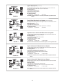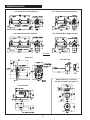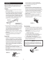
1
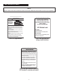
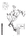
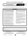
Operation and Installation Instructions
691 LOCK SYSTEM
READ GENERAL INSTALLATION GUIDELINES SHEET (FORM NO. 81-600-001) BEFORE PROCEEDING.
1. The MICO 691 System is a supplemental safety
device which provides additional brake holding
action when used with existing vehicle parking
brake. It is not for dynamic service braking.
2. The 691 System must be used in combination with
an audible and/or visual alarm as a warning to
signal the user of any loss of brake system pressure. Do not disconnect warning devices.
3. All lines, fittings and surrounding areas must be
cleaned of dirt or road residue before any lines or
fittings are disconnected. Special care must be
taken so dirt and road residue are not allowed to
enter the hydraulic brake system. This can contaminate the system and interfere with proper
operation of brakes and MICO 691 System.
4. Follow procedures outlined in Vehicle Manufacturer’s Service Manual or SAE Standards when
making new connections or adding to existing
brake systems. Use only steel brake tubing conforming to SAE specifications.
5. Vehicle Brake System: Always use clean fluid
conforming to vehicle manufacturer’s recommendations. 691 Power Unit: See BEFORE
PROCEEDING, page 3 for proper fluid type.
Improper or contaminated fluid may cause gummy
deposits, softening and swelling of rubber seals,
and may render the 691 System inoperative.
Such a condition must be corrected immediately.
6. Do not use sealants, tapes, teflon or cement
compounds on any connections or fittings. These
sealants or compounds can contaminate the
hydraulic brake system and interfere with the
operation of brake components or MICO 691
System.
7. All fittings and connections must be in good
condition and properly torqued.
8. Brake hoses, brake lines, MICO 691 System,
brake components, cylinders, and all fittings must
be routinely inspected for leaks, damage or wear.
Proper fluid levels must be maintained. In the
event of any loss of fluid, brake system must be
carefully inspected for leaks.
9. When installation of MICO 691 System is complete, 691 System and brake system must be
bled of air. Bleed MICO 691 System according to
procedures outlined in this manual. Bleed brake
system according to vehicle manufacturer’s
recommendations.
10. The self-adhesive warning labels, page 1, accompanying each MICO locking device must be
affixed in the vehicle cab in view of operator.
11. Keep this manual in the cab of the vehicle after
installing the 691 System.
MICO could not possibly know of and give advice with respect to all conceivable applications in which this product may be used and the possible hazards and/or
results of each application. MICO has not undertaken any such wide evaluation. Therefore, anyone who uses an application which is not recommended by the
manufacturer, first must completely satisfy himself that a danger will not be created by the application selected, or by the particular model of our product that is
selected for the application.
MICO has made every attempt to present accurate information in catalogs, brochures and other printed material. MICO can accept no responsibility for errors
from unintentional oversights that may exist. Due to a continuous program of product improvement, materials, specifications, and product documentation are sub ject to change without notice or obligation.
MICO is a registered trademark of MICO, Incorporated. MICO is registered in the U.S. Patent and Trademark Office as well as in Australia, Canada, Great Britain, Indonesia, Japan, Peoples Republic of China, and South Korea.
MICO, Incorporated
MICO West Division
1911 Lee Boulevard (Zip Code 56003-2507)
P.O. Box 8118 / North Mankato, MN U.S.A. 56002-8118
( 507.625.6426 Facsimile 507.625.3212
701 East Francis Street (Zip Code 91761-5514)
P.O. Box 9058 / Ontario, CA U.S.A. 91762-9058
( 909.947.4077 Facsimile 909.947.6054
Form No. 81-690-032
Revised 3/25/04
Printed in U.S.A.
Table of Contents
Page
SELF ADHESIVE LABELS . . . . . . . . . . . . . . . . . . . . . . . . . . . . . . . . . 1
INTRODUCTION . . . . . . . . . . . . . . . . . . . . . . . . . . . . . . . . . . . . . . 2
PRINCIPLE OF OPERATION . . . . . . . . . . . . . . . . . . . . . . . . . . . . . . . . 2
INSTALLING A 691 SYSTEM. . . . . . . . . . . . . . . . . . . . . . . . . . . . . . . . 3
IDENTIFY YOUR BRAKE SYSTEM . . . . . . . . . . . . . . . . . . . . . . . . . . . . 3-4
DIMENSIONAL DATA . . . . . . . . . . . . . . . . . . . . . . . . . . . . . . . . . . . 5
MOUNTING . . .
Actuator . . . .
Power Unit . .
Control Module
User Interface .
.
.
.
.
.
.
.
.
.
.
.
.
.
.
.
.
.
.
.
.
.
.
.
.
.
.
.
.
.
.
.
.
.
.
.
.
.
.
.
.
.
.
.
.
.
.
.
.
.
.
.
.
.
.
.
.
.
.
.
.
.
.
.
.
.
.
.
.
.
.
.
.
.
.
.
.
.
.
.
.
.
.
.
.
.
.
.
.
.
.
.
.
.
.
.
.
.
.
.
.
.
.
.
.
.
.
.
.
.
.
.
.
.
.
.
.
.
.
.
.
.
.
.
.
.
.
.
.
.
.
.
.
.
.
.
.
.
.
.
.
.
.
.
.
.
.
.
.
.
.
.
.
.
.
.
.
.
.
.
.
.
.
.
.
.
.
.
.
.
.
.
.
.
.
.
.
.
.
.
.
.
.
.
.
.
.
.
.
.
.
6
6
6
6
6
PLUMBING . . . . . . . . . . . . . . . . . . .
Single 691 Brake Lock System . . . . . . . .
Dual 691 Brake Lock System . . . . . . . . .
3 Channel Anti-Lock 691 Brake Lock System .
4 Channel Anti-Lock 691 Brake Lock System .
.
.
.
.
.
.
.
.
.
.
.
.
.
.
.
.
.
.
.
.
.
.
.
.
.
.
.
.
.
.
.
.
.
.
.
.
.
.
.
.
.
.
.
.
.
.
.
.
.
.
.
.
.
.
.
.
.
.
.
.
.
.
.
.
.
.
.
.
.
.
.
.
.
.
.
.
.
.
.
.
.
.
.
.
.
.
.
.
.
.
.
.
.
.
.
.
.
.
.
.
.
.
.
.
.
.
.
.
.
.
7
7
7
8
8
WIRING . . . . . . . . . . . . . . . . . . .
Wiring Instructions. . . . . . . . . . . . .
Connecting External Inputs . . . . . . . .
Connecting the Vehicle Horn . . . . . . .
Connecting Power for the Control Module
.
.
.
.
.
.
.
.
.
.
.
.
.
.
.
.
.
.
.
.
.
.
.
.
.
.
.
.
.
.
.
.
.
.
.
.
.
.
.
.
.
.
.
.
.
.
.
.
.
.
.
.
.
.
.
.
.
.
.
.
.
.
.
.
.
.
.
.
.
.
.
.
.
.
.
.
.
.
.
.
.
.
.
.
.
.
.
.
.
.
.
.
.
.
.
.
.
.
.
.
.
.
.
.
.
.
.
.
.
.
9
9
9
9
9
.
.
.
.
.
.
.
.
.
.
BLEEDING . . . . . . . . . . . . . . . . . . . . . . . . . . . . . . . . . . . . . . . . . 10
Tips on Bleeding Brake Systems . . . . . . . . . . . . . . . . . . . . . . . . . . . . . 10
Bleeding Procedures . . . . . . . . . . . . . . . . . . . . . . . . . . . . . . . . . . 10-11
HORN WARNING CIRCUIT TEST . . . . . . . . . . . . . . . . . . . . . . . . . . . . . 11
691 OPERATING INSTRUCTIONS . . . . . . . . . . . . . . . . . . . . . . . . . . . . 11
Using 691 as a Lock System . . . . . . . . . . . . . . . . . . . . . . . . . . . . . . . 11
Using 691 as an Interlock. . . . . . . . . . . . . . . . . . . . . . . . . . . . . . . . . 12
691 System Installation Checklist . . . . . . . . . . . . . . . . . . . . . . . . . . . (Insert)
BRAKE LOCK APPLICATIONS (Wiring Diagram) . . . . . . . . . . . . . . . . . . . . 14
INTERLOCK APPLICATIONS (Wiring Diagram) . . . . . . . . . . . . . . . . . . . . . 15
TROUBLESHOOTING . . . . . . . . . . . . . . . . . . . . . . . . . . . . . . . . . . 16-18
691 MODEL NUMBERS . . . . . . . . . . . . . . . . . . . . . . . . . . . . . . . . . 19-20
691 ACCESSORIES . . . . . . . . . . . . . . . . . . . . . . . . . . . . . . . . . . . . 19
SELF ADHESIVE LABELS
NOTE
All 691 models include the self adhesive labels shown below. Determine which labels are used in your application.
THIS NOTICE MUST BE AFFIXED ON DASH IN VIEW OF OPERATOR
!
THIS NOTICE MUST BE AFFIXED ON DASH IN VIEW OF OPERATOR
WARNING
Serious injury
or death can
occur if these
instructions are
not followed
Operator must read and
understand Warnings and
Operating Instructions before
using vehicle
(Form no. 81-690-032).
PREVENT
ROLLAWAY
This vehicle is equipped with 691 Brake Lock System.
Operator must read and understand warnings and
operating instructions before using vehicle (Form no.
81-690-032) .
691 Brake Lock
Do not use 691 Brake Lock in place of original equipment parking brake.
TO LOCK:
Always apply parking brake and other provided holding devices when using 691 System.
1. Set parking brake
2. Move lock switch to LOCK position
Do not use 691 Brake Lock for overnight or prolonged
parking.
TO RELEASE:
1. Move lock switch to RELEASE position
2. Release parking brake
Release 691 Brake Lock before moving vehicle.
691 Brake Lock and warning circuit are disabled if
battery power is lost or disconnected.
Use in all applications
using a user interface.
Use in all applications.
THIS NOTICE MUST BE AFFIXED ON DASH IN VIEW OF OPERATOR
WARNING
Serious injury or death can occur if
these instructions are not followed.
Operator must read and understand warnings
and operating instructions before using vehicle
(Form no. 81-690-032).
This vehicle is equipped with a 691 Brake Lock
System that is activated by a remote input.
Unintended operation of the remote input will
cause the brakes to apply or release without
warning.
The operator must understand the function of
the remote inputs.
Be aware of all conditions that will cause the
691 Brake Lock System to activate or deactivate without user intervention.
Use in all applications where the
691 System is remotely activated.
1
The Actuator (Figure 3)
INTRODUCTION
The actuator is a mechanical device that links the
hydraulics of the 691 System to the vehicle service
brake system. The actuator separates the 691 System
fluid from the vehicle service brake system. Various
actuators are available for use in different types of
service brake systems.
Vehicles today have two separate brake systems. One is
the service brake system and the other is the parking
brake system. The service brake system is used to slow or
stop a vehicle during normal operation. The parking brake
system is usually cable operated and used to hold the
vehicle stationary while parked.
Experience has shown that some vehicle applications require more brake holding capacity than provided by properly maintained parking brakes. The MICO 691 Brake
Lock System uses the vehicle service brakes to supplement the parking brake. The 691 System provides pressure to the service brake system in the same manner as
when the
vehicle operator presses on the brake pedal.
The 691 also provides external inputs which can activate
the system without direct operator interjection.
The 691 Brake Lock System consists of:
FIGURE 3
The Control Module and User Interface
(Figure 1)
PRINCIPLE OF OPERATION
The control module controls operation of the system
through the user interface or remote activation. The
user interface incorporates a manually activated switch,
audible alarm, and "locked" lamp.
1. When the 691 System is activated, the control module
starts the power unit pumping fluid into the actuator(s).
As the actuator(s) become pressurized they isolate the
vehicle master cylinder and pressurize the service
brakes.
When lock pressure is reached, the high-pressure
switch signals the control module to stop the pump.
While the pump is stopped, locking pressure is held in
the brake system. If locking pressure drops, the high
pressure switch signals for the power unit to turn "on"
and restore locking pressure.
2. When the 691 System is deactivated, the pump
reverses and releases pressure. The actuator releases
pressure from the brakes and opens the ports to the
vehicle master cylinder. When locked pressure returns
to zero psi a signal from the low-pressure switch stops
the pump.
Control Module
User Interface
FIGURE 1
The Power Unit (Figure 2)
The power unit uses a 12 volt DC pump to produce
pressure in the vehicle service brake system to lock
the brakes. The pump reverses flow to release locking
pressure.
Two pressure switches are located on the power unit.
The pressure switches sense the pressure that the
power unit is producing. The high pressure switch
starts and stops the pump while pressurizing the system. The low pressure switch starts and stops the
pump while releasing pressure from the system.
Although the power unit contains a built in fluid
reservoir, a remote reservoir is available as an option
for special applications. Refer to 691 Accessories chart
on page 19.
NOTE
Brake System fluid and 691 System fluid always remain isolated
from one another.
FIGURE 2
2
BEFORE PROCEEDING:
INSTALLING A 691 SYSTEM
1. Identify your vehicle brake system. See pages
3 & 4.
2. Be sure you have the correct 691 model number
and it contains all the parts. Refer to Table 1 (pages
19 & 20).
All vehicles currently using automotive brake
fluid (DOT 3, 4, 5 or 5.1) in the brake system must
use the 691 model numbers designated (SF). All
vehicles currently using mineral base hydraulic oil in
the brake system must use the 691 model numbers
designated (HO).
3. Check brake pedal height and feel. With the vehicle
running, push on the brake pedal until there is no
more forward movement. Measure and record the
distance from pedal to floor. Brake pedal height and
"feel" will be the same after the 691 System is installed, refer to Figure 4.
There are four steps to installing the 691 System.
1. Mounting
2. Plumbing
3. Wiring
4. Bleeding
The 691 System must only be installed by someone with
good working knowledge of automotive brake and electrical systems.
It is important that the installer of the 691 System understands fluid types used in various 691 Systems. Read and
understand this instruction manual before installing the 691
Brake Lock System.
Brake System Fluid
For all 691 installations the vehicle’s brake system
fluid does not change. Vehicles currently using
brake fluid in the brake system will continue to use
brake fluid. Vehicles currently using mineral base
hydraulic oil in the brake system will continue to use
mineral base hydraulic oil.
691 System Fluid
FIGURE 4
The two 691 Power Unit designs, DOT 5 silicone fluid
(SF) and mineral base hydraulic oil (HO), assure seal
compatibility with your existing brake system.
NOTE: Power unit and brake system fluids do not
become intermixed when a 691 System is installed.
The 691 Actuator(s) isolate the 691 System fluid
from the brake system.
IDENTIFY YOUR BRAKE SYSTEM
Typical hydraulic braking systems in use today vary
depending on manufacturer and size of vehicle. For instance, a vehicle equipped with a single system may have
a firewall mounted booster or possibly a frame mounted
remote booster. The same holds true for the dual and split
systems. The rear wheel anti-lock system is a dual brake
system with an anti-lock valve installed. All-wheel anti-lock
systems are defined as 3-channel or 4-channel systems
(Check the number of outlet lines from the anti-lock control
valve). To be absolutely sure which braking system your
vehicle is equipped with, check it. Look for identifying features such as dual flex lines at rear axle or front wheels,
number of master cylinder lines, anti-lock valve(s), etc.
Then, compare with the circuits shown in Figures 5 thru
11.
Typical Single System
One single hydraulic system serving both front and rear brakes.
Identifying Feature:
1.One line from master cylinder.
691 Actuator Position:
(1) Front axle
(2) Rear axle
(3) 4-wheel
FIGURE 5
Typical Dual System (Vertical Split)
FIGURE 6
Two independent braking systems. One system leads to the front brakes and the
other system to the rear brakes.
Identifying Feature:
1.Two lines from master cylinder.
2.Combination valve (used on some models).
691 Actuator Position:
(1) Front axle
(2) Rear axle*
(3) 4-wheel
* Some imported vehicles use two separate air boosted master cylinders.
3
Typical Split System (1 1/2 x 1/2)
Two independent braking systems. One system leads to the front and the rear
brakes and the other system leads only to the rear brakes.
Identifying Feature:
1.Two lines from master cylinder.
2.Single hose to each front wheel.
3.Two hoses to rear axle.
691 Actuator Position:
(1) Front axle
(2) Rear axle
(3) 4-wheel
FIGURE 7
CAUTION: Whether position 2 or 3 is used, both halves of system must be
locked.
Typical Rear Wheel Anti-Lock System (Dual Vertical Split)
Two independent braking systems. One system leads to the front brakes and the
other system to the rear brakes.
Identifying Feature:
1.Two lines from master cylinder.
2.Anti-lock control valve between master cylinder and rear wheels.
691 Actuator Position:
(1) Front axle
(2) Rear axle
(3) 4-wheel
FIGURE 8
Imported Truck 3-Channel All-Wheel Anti-Lock System
Provides braking control by way of independent anti-lock channels for each rear
wheel and a third channel for the front wheels.
Identifying Feature:
1.Three separate air/hydraulic brake boosters.
2.One line to front brakes.
3.Separate lines to each rear wheel.
691 Actuator Position:
(1) Front axle
(2) Rear axle
(1 & 2) 4-wheel
FIGURE 9
NOTE: The anti-lock functions on air booster system, not the hydraulic side.
Typical 3-Channel All-Wheel Anti-Lock System
Provides braking control by way of independent anti-lock channels for each front
wheel and a third channel for both rear wheels.
Identifying Feature:
1.Two lines from master cylinder to anti-lock valve(s).
2.One line from anti-lock valve to rear brakes.
3.Separate lines from anti-lock valve to each front wheel.
691 Actuator Position:
(1) Front axle
(2) Rear axle
(1 & 2) 4-wheel
FIGURE 10
NOTE: Some 3-channel anti-lock brake systems use two separate anti-lock
valves.
Typical 4-Channel All-Wheel Anti-Lock System
Provides braking control by way of an independent channel for each front wheel
and each rear wheel.
Identifying Feature:
1.Two lines from master cylinder to anti-lock valve.
2.Separate lines from anti-lock valve to each of the front and rear wheels.
691 Actuator Position:
(1) Front axle
(2) Rear axle
(1 & 2) 4-wheel
FIGURE 11
NOTE: Some 4-channel anti-lock brake systems use two separate anti-lock
valves.
4
DIMENSIONAL DATA
1 1/4" Diameter Bore Dual Actuator
1 1/4" Diameter Bore Single Actuator
1 3/4" Diameter Bore Dual Actuator
1 3/4" Diameter Bore Single Actuator
millimeters
inches
Power Unit
User Interface
Remote Reservoir - (optional)
See 691 Accessories on page 19
Control Module
5
power unit reservoir. Check the CAUTION label
around the power unit reservoir breather/filler plug
to verify fluid type, refer to Figure 13.
MOUNTING
Several self adhesive labels are supplied with each 691
Brake Lock. Determine which labels are used in your
application and affix in the vehicle cab in view of the
operator. See page 1.
Control Module
1. A mounting bracket is provided with the 691 Control
Module to mount the control module directly to the
691 Power Unit. See power unit dimensional drawing
on page 5. The control module can be mounted on top
of the power unit as shown, as well as mounted to
either side. The control module can also be mounted
to position the harness connection in the opposite
direction shown.
2. When the 691 Control Module is not mounted to the
691 Power Unit, an optional 11' wire harness
(32-820-022) is available from MICO, Inc. See page
19 for 691 Accessories.
Actuator
1. Repeat the mounting procedures for each actuator
used in your system.
2. Find a location, preferably on the frame rail away from
heat, where the actuator(s) will mount allowing easy
access to brake lines, refer to Figure 12. The actuator(s) must be mounted horizontally below the level of
the vehicle master cylinder. The bleeder screws must
be in an upright position. Relocate the bleeder screws
as necessary to maintain upright position. Torque
bleeder screws 17.6-20.3 N-m (13-15 lb-ft).
FIGURE 12
FIGURE 14
RECOMMENDED ACTUATOR
MOUNTING LOCATION INSIDE OR OUTSIDE FRAME RAIL
3. Using the actuator mounting brackets as a template,
mark and drill four 11/32" diameter holes. Fabricated
mounting brackets can be used to mount the actuator(s). The strength of fabricated brackets must be
adequate to prevent flexing of brake lines.
4. Install the actuator using four 5/16-18UNC, grade 5,
bolts, lock washers, and nuts. Torque 27.1-33.9 N-m
(20-25 lb-ft).
5. Install the brass adapters from the fitting package
in the actuator ports and torque 7.9-10.2 N-m
(70-90 lb-in).
User Interface
1. A dash mounted user interface is provided for use by
the operator in the cab. The user interface includes a
manually activated switch, audible alarm, and "locked"
lamp. Find a mounting location in the cab of the
vehicle where:
A. The operator has easy access to the "lock" "release" rocker switch.
B. The "lock" lamp is visible to the operator.
C. It is protected from having something spilled on it.
D. There is easy routing of wires from the 691
Control Module to the user interface.
2. The user interface is not necessary for applications
where the 691 System is activated by other manual
switches or electrical interlocks.
Power Unit
1. The power unit can be mounted in the engine compartment, on the frame rail, or in the cab. However,
it must be protected from dirt, moisture and possible
impact. Easy access to the reservoir breather/filler
plug must be maintained to allow for filling and checking fluid level. The reservoir breather plug must be
kept in an upright position. If this is not possible a
remote reservoir can be installed, refer to 691 accessories on page 19.
2. Mark and drill two 7/16" diameter holes 2 5/16" apart.
Fabricated mounting brackets can be used.
3. Mount the power unit using two 3/8-16UNC bolts and
lock washers.
4. 691 models designated (HO) must use mineral base
hydraulic oil in the power unit reservoir. 691 models
designated (SF) must use DOT 5 silicone fluid in the
NOTE
When the 691 User Interface is not installed with this
system, another visual identifier must be used to inform
the operator that the 691 System is "locked". See schematic on page 14.
FIGURE 15
FIGURE 13
Pressure
Switches
CAUTION Label
6
5. Connect one end of the new tubing to the single
actuator.
6. Connect the other end of the new tubing to the power
unit. This connection can be made to either the side
or top port. Remove the plastic shipping plug from the
top port. To install line in the side port use 3/16" hex
key wrench to move the steel plug from side port to
top port. Install the remaining brass adapter from the
fitting package in the selected port prior to connecting
the line. See Figure 18.
PLUMBING
Determine the type of brake system on your vehicle, refer
to pages 3 & 4. All brake systems in use today require the
MICO 691 Actuator(s) be installed after the anti-lock brake
valve and combination warning valve if so equipped.
Contact MICO, Incorporated if you have questions.
Single 691 Brake Lock System
Plug One of
These Ports
FIGURE 18
Single Brake System
1. Disconnect the existing brake line necessary to install
the single actuator. Reduce fluid loss by plugging the
ports. Do not loosen or remove hydraulic lines that are
not effected by the installation of the single actuator.
2. Determine the length and shape of new or modified
brake lines needed to install the actuator. The installer
must be qualified to modify existing brake tubing, or
new factory double flared SAE approved brake line
must be used. When adding or replacing brake lines,
do not use smaller diameter than existing lines. The
MICO 691 Actuator is supplied with brass adapters
designed to mate with 1/4" inverted flare tube nuts.
Contact MICO, Incorporated or a local brake fitting
supplier to obtain proper fittings to install different size
lines. All new connections or modifications between
flexing vehicle sections, such as vehicle body and
frame, must be made to absorb shock and vibration.
Common methods used to absorb this shock are
coiling the brake tubing or using a short length of
purchased brake hose. Follow procedures outlined by
the vehicle manufacturer or SAE specifications.
3. Connect the upstream line coming from the vehicle
master cylinder to the fluid inlet port on the end of the
single actuator. Connect the downstream line going to
either the front or rear brakes from the side outlet port
on the same end of the single actuator. See Figure 16.
Single Brake System with 691 System
Dual 691 Brake Lock System
Dual Brake Systems
1. Disconnect the existing rear brake lines necessary to
install the dual actuator. Reduce fluid loss by plugging
the ports. Note which master cylinder port supplies
fluid to the front brakes and rear brakes. Do not
reverse the front and rear fluid paths during the
installation of new brake lines.
2. Determine the length and shape of new or modified
brake lines needed to install the dual actuator. The
installer must be qualified to modify existing brake
tubing, or new factory double flared SAE approved
brake line must be used. When adding or replacing
brake lines, do not use smaller diameter than existing
lines. The MICO 691 Actuator is supplied with brass
adapters designed to mate with 1/4" inverted flare
tube nuts. Contact MICO, Incorporated or a local
brake fitting supplier to obtain proper fittings to install
different size lines. All new connections or modifications between flexing vehicle sections, such as vehicle
body and frame, must be made to absorb shock and
From
Master Cylinder
(port not shown)
To Brakes
FIGURE 16
4. Determine the shape and length of a new piece of
tubing to connect the power unit and single actuator.
See Figure 17.
FIGURE 17
From
Power Unit
7
vibration. Common methods used to absorb this shock
are coiling the brake tubing or using a short length of
purchased brake hose. Follow procedures outlined
by the vehicle manufacturer or SAE specifications.
3. Connect the upstream line coming from the master
cylinder to the fluid inlet port on one end of the actuator. Note that the actuator is not directional and does
not have a front and rear. Connect the downstream
line going to the rear brakes from the side outlet port
on the same end of the dual actuator. See Figure 19.
3 Channel Anti-Lock 691 Brake Lock
System
From
Master Cylinder
(port not shown)
3 Channel Anti-lock Brake System
The 3-channel anti-lock brake system uses both a single
and a dual actuator. Follow the plumbing instructions for
both the Single 691 Brake Lock System and the Dual 691
Brake Lock System to connect the appropriate lines. To
connect the hydraulic line from the power unit to both
actuators, either a tee can be added to this line or the plug
in the unused port on the pressure switch manifold can be
removed to accommodate the connection.
FIGURE 19
To
Brakes
From
Master Cylinder
To
Brakes
4. Repeat steps 1, 2 & 3 to install the front brake lines.
5. Determine the shape and length of a new piece of
tubing to connect the power unit and dual actuator.
6. Connect one end of the new tubing to the dual
actuator. See Figure 20.
Plug One of
These Ports
3 Channel Anti-lock Brake System with 691 System
4-Channel Anti-Lock 691 Brake
Lock System
From
Power Unit
FIGURE 20
FIGURE 21
7. Connect the other end of the new tubing to the power
unit. This connection can be made to either the side or
top port. Remove the plastic shipping plug from the
top port of the power unit. To install line in the side
port use 3/16" hex key wrench to move the steel plug
from side port to top port. Install the remaining brass
adapter from the fitting package in the selected port
prior to connecting the line. See Figure 21.
4 Channel Anti-lock Brake System
The 4-channel anti-lock brake system uses two dual
actuators. Follow the plumbing instructions for the Dual
691 Brake Lock System to connect the appropriate lines.
To connect the hydraulic line from the power unit to both
actuators, either a tee can be added to this line or the plug
in the unused port on the pressure switch manifold can be
removed to accommodate the connection.
Dual Brake Systems with 691 System
4 Channel Anti-lock Brake System with 691 System
8
2. The brown wire in the main 691 Wire Harness.
NOTE: These inputs are connected together
internally, so if one is receiving a positive signal, the other will also have a positive signal
present. This is commonly used to provide an
external signal (to the brown wire) when the
switch on the 691 User Interface is activated.
To prevent unintentional activation of the 691 System,
insulate and seal any of the unused wires.
WIRING
Power is supplied to the 691 Control Module at all times.
To prevent unintended actuation of the 691 System, be
sure the "lock" - "release" switch (if applicable) is in the
"release" position.
Using the Brown Wire as an External Output
Do not operate the 691 Power Unit without first filling the
power unit reservoir with proper fluid.
When activating the 691 System with the user interface,
the brown wire can be used to signal other circuits. It will
provide a positive signal up to 1 amp of power to lights,
relays, etc. If this current limit is exceeded, the output or
control module may operate erratically or not at all.
691 Wiring Instructions
(Refer to diagrams on pages 14 & 15)
The 691 System is designed for use on vehicles with a
12 volt DC, negative ground system. References to
"ground" in this literature refer to vehicle chassis ground
which is connected to the negative (-) battery terminal.
References to "hot" or "positive" refer to connection to the
positive (+) terminal of the 12 volt DC battery.
*NOTE: The brown wire will not provide an output
when the 691 System is activated by the external input
of the gray wire. This is an inherent design to provide
protection from improper wiring.
If the gray wire is allowed to short to ground, the vehicle brakes will apply.
NOTE
All positive connections to the battery must be made
through a high quality, properly rated fuse. Do not use a
slow blow fuse or circuit breaker.
Connecting the Vehicle Horn
The yellow 691 harness wire must be connected to a horn
or other suitable warning device for your application. The
yellow wire sends a ground signal to sound the horn when
necessary.
1. On most vehicles the best way to connect this wire
without adding a relay is to find the horn wire from
the horn switch in the steering wheel. This switch
typically grounds this wire to sound the horn, splicing in the yellow wire at this point is all that is
necessary.
2. If splicing into the horn switch wire is not convenient,
add a relay that is switched by the ground signal from
the yellow wire and that connects the appropriate
signal directly to the horn itself.
The yellow wire will provide a ground of up to 1
amp to drive a warning device. If this current limit is
exceeded or if the yellow wire is connected improperly, the warning device or control module may operate
erratically or not at all. Be sure to check for proper
operation of the horn circuit on a regular basis. See
page 11, "HORN WARNING CIRCUIT TEST".
Optional extension harness (32-820-022, page 19) is available from MICO, Incorporated when the control module is
not mounted directly to the power unit. The supplied wire
harness has been designed with sufficient wire length to
complete most installations. If additional wire is necessary,
be sure to use the proper gauge.
When making wire connections, soldering and sealing with
adhesive lined heat shrink is the recommended method.
All wires that are not used must be sealed and insulated to
keep from shorting to each other or ground.
Connecting External Inputs
Activating the 691 System by use of the user interface
rocker switch is not always convenient. External inputs can
activate the 691 System through the use of external
switches, dash mounted switches or relays. This provides
flexibility for manual operation by the user or allows other
circuits to activate the brakes.
External Inputs
There are three external inputs available. The 691 is
activated upon receiving a signal at any of the inputs and
does not deactivate until all input signals have been
removed.
Two of the external inputs are activated by a positive signal (+12 VDC) and the third is activated by a negative
(ground) signal.
The negative input is accessed from the gray wire in the
main 691 Wire Harness.
The two positive inputs are:
1. The green wire in the user interface cable.
Connecting Power for the Control Module
1. Connect the black wire directly to battery negative or
equivalent ground. This wire carries the full current of
the 691 System and must have a good ground. If
additional wire is necessary for this connection it must
be a minimum of 14 gauge wire.
2. Connect the red wire to a 30 amp fuse which is
connected directly to battery positive. This wire also
carries full 691 System current. Do not connect this
through any auxiliary wiring. Do not use a slow blow
fuse or circuit breaker.
9
Bleeding Procedures
BLEEDING
NOTE
To assure successful brake system bleeding, complete
all bleeding procedure steps in the order that they are
listed.
Vehicle Brake System: Always use clean fluid conforming to vehicle manufacturer’s recommendations.
691 Power Unit: Check the CAUTION label on the
691 Power Unit reservoir for proper fluid type. Refer
to Figure 13.
Brake System
Bleed Point
All electrical connections must be completed and the
power unit reservoir filled with proper fluid before bleeding.
The hydraulic brake system must be bled whenever any
line has been disconnected. Although we recommend the
use of pressure bleeding equipment when bleeding the
system, some vehicle manufacturers do not advise certain
bleeding methods. Refer to Vehicle Manufacturers bleeding recommendations. When pressure bleeding, use a
system pressure of 1.72-2.07 bar (25-30 psi).
Brake System
Bleed Point
FIGURE 22
1. Disconnect the vehicle horn and other warning
devices.
2. Be sure the 691 Power Unit reservoir remains filled
with the proper fluid during entire bleeding process.
Check the CAUTION label on the 691 Power Unit
reservoir for proper fluid type.
3. Make sure the vehicle master cylinder reservoir is full
of fluid specified by the vehicle manufacturer.
4. Gravity Bleed - After the initial installation, DO NOT
apply the brake pedal. Remove the cap from the
master cylinder reservoir. One at a time, open each
bleeder screw in the vehicle brake system beginning
with bleeder screws on the actuators and moving
outward to the foundation brakes. NOTE: In some
situations, to save time, all bleeder screws may be
opened simultaneously. Do not deplete reservoir
fluid level. When a steady stream of fluid is present,
close the bleeder and proceed to the next. If gravity
flow is not obtained within 5 minutes, proceed to next
step. (Also check for blocked or crimped lines, or
loops in tubing where air may be trapped).
5. Manual Bleed - Manually bleed the brakes, depressing and releasing brake pedal slowly and to disperse
fluid through the brake system without agitating it. Do
not depress pedal when bleeder screw is closed. Do
not release pedal when bleeder screw is open. Bleed
691 Actuators first. After actuators are bled, continue
by bleeding foundation brakes.
A. Open bleeder screw, then slowly apply the pedal
to the limit of its stroke.
B. Close the bleeder and slowly release the pedal.
C. Repeat this process multiple times at each bleed
point without pumping the pedal in-between.
Tips on Bleeding Brake Systems
1. Patience is often necessary. Brake fluids can be easily
aerated by being forced through tubes too fast or
agitating them. Once brake fluid has been aerated, the
best way to get the air back out is to let it sit. Several
hours or overnight may be necessary.
2. While bleeding, make every effort to move the fluid
slowly. This is especially important when applying the
brake pedal and when opening bleeder screws.
3. Avoid rapid pumping of the brake pedal as it can
cause the fluid to become aerated.
4. Always wear safety glasses and be cautious when
opening bleeder screws with any pressure applied. Air
pockets will shoot the fluid out at a rapid rate.
5. Connect a length of poly-style air line from the bleeder
screw into a container to recapture the fluid during the
bleeding process.
6. In some cases, gravity bleeding is the best form of
bleeding.
7. Start bleeding process at the actuators and work
toward the foundation brakes.
8. Even when the brake system seems to be well bled, it
may still contain small amounts of air. We recommend
re-bleeding the brake system after the vehicle has
been parked overnight.
10
6. Pressure Bleed - There are two options for pressure
bleeding the brake system, either using a commercial
pressurized bladder type bleeder or by activating the
691 Power Unit.
Using commercial bleeder
Follow manufacturer's instructions.
Using 691 Power Unit
A. Activate the 691 System.
Be careful when opening the bleeder screw, it will be under high pressure. Wear safety glasses.
B. Starting at the actuators and moving outward to
foundation brakes, open bleeder screw 1/2
turn. The 691 Power Unit will run with the release of pressure and will stop automatically
when the actuator reaches the end of its stroke.
Most air will come out at end of the actuator
stroke.
C. After power unit stops running, close the
bleeder screw.
D. Deactivate the 691 System. After 691 Power
Unit stops running, slowly depress and release
brake pedal 3 to 5 times or until a firm pedal is
achieved. This step is to replenish the actuators. NOTE: The 691 Power Unit will run
during first brake application.
E. Be sure the 691 Power Unit reservoir and
vehicle master cylinder reservoir remain filled
with proper fluid.
F. Repeat steps A thru E at each bleed point until
all air is purged before switching to the next
bleed point.
G. After the above steps are completed, check to
see if brake pedal height and "feel" are the
same as before the 691 System was installed.
If the pedal does not "feel" as firm as before, let
the vehicle sit for several hours or overnight
and repeat pressure bleeding.
7. Activate the 691 System. Open bleeder screw 1/4
turn. See Figure 23. Close bleeder screw when a
steady stream of fluid is present.
Power Unit
Bleed Point
Power Unit
Bleed Point
8. Reconnect horn or other warning devices.
HORN WARNING CIRCUIT TEST
The 691 Control Module provides two alarm wires: "direct
alarm" and "delayed alarm". The "direct alarm" wire is the
white wire in the User Interface cable. It provides a ground
signal whenever the system is pressurizing. It activates the
User Interface audible alarm. The "delayed alarm" wire,
the yellow wire in the main 691 wire harness, is also
referred to as the horn wire. It provides a ground signal if
the system takes longer than nine seconds to initially pressurize, or anytime the system is re-pressurizing.
The yellow wire must be connected to the vehicle's horn or
to a form of warning device that will guarantee that the
operator is aware that the system is re-pressurizing.
The horn warning circuit must be tested on a regular basis.
After the system has been activated and is locked,
momentarily unplug the 2-wire (black & white) connector
leading to pressure switch #2 (stamped "1-800"). While
unplugged, the horn will activate.
If the horn does not activate during this test, determine the
cause of the problem and correct before using the 691
Brake Lock System.
691 OPERATING INSTRUCTIONS
Do not operate power unit without first filling with
proper fluid.
Using 691 as a Lock System
(Only units with 691 User Interface)
To Activate Lock System
1. Bring vehicle to a complete stop.
2. Set mechanical parking brake.
3. Move the user interface lock/release switch to the
"lock" position.
4. User Interface alarm will sound and then deactivate
after reaching locking pressure.
5. The "locked" indicator lamp will come on after locking
pressure is reached.
6. Apply other provided holding devices.
NOTE
FIGURE 23
Before moving the vehicle, a firm pedal must be
achieved when the 691 System is deactivated. If a firm
pedal is not achieved, repeat bleeding procedure for
the 691 System and the service brake system until a
firm pedal is achieved. Make several brake applications with vehicle stationary and check fittings for
leaks.
If pressure drops below required system pressure, the
"locked" indicator lamp will go off and user interface
alarm will activate. This process may take only a fraction of a second.
If user interface alarm does not sound or fails to deactivate or if the "locked" indicator lamp does not remain
on, discontinue use of the 691 Brake Lock System.
Determine the cause of the problem and correct before
using.
11
To Deactivate Lock Device
1. Disengage other provided holding devices.
2. Switch the user interface to "release" position. The
"locked" indicator lamp will deactivate and the power
unit will return brake system to static system pressure.
3. Release mechanical parking brake.
Using 691 as an Interlock
NOTE
The 691 Interlock can be activated by the rocker
switch (if applicable) whether the vehicle’s ignition is
on or off as long as the battery connection exists.
To Activate
1. Bring vehicle to a complete stop.
2. Set mechanical parking brake.
3. Satisfy the conditions that activate remote input.
To Deactivate
1. Disengage other provided holding devices.
2. Deactivate remote input.
3. Release mechanical holding devices.
NOTE
To release the brakes in case of an electrical failure
complete the following steps:
A. Remove 691 System fuse.
B. Apply other provided holding devices and
mechanical parking brake to keep the vehicle
from rolling.
C. Release residual pressure from 691 System by
carefully loosening bleeder screw nearest the
power unit inlet port of 691 Actuator. Be careful
when opening the bleeder screw, it may be under
high pressure.
D. Disengage other provided holding devices.
E. Release mechanical parking brake.
12
691 System Installation Checklist
NOTE: As you install the 691 System complete this check list. Upon completion of the 691 installation,
retain this checklist with the 691 Operation and Installation Manual.
Date installed: _______________ Name of person(s) installing: ______________________________________
Vehicle make:______________________________Model: _______________________Year: _______________
Vehicle I.D. number: _________________________________________________________________________
Model number of 691 System installed: _________________________________________________________
Complete this section after Mounting the 691 System
o Yes
o No
1. Is the 691 Power Unit mounted upright and level?
o Yes
o No
2. Is the power unit breather plug clean and away from contaminants?
o Yes
o No
3. Can the fluid in the power unit reservoir be easily checked?
o Yes
o No
4. Is the actuator(s) mounted at a lower level than the vehicle master cylinder?
o Yes
o No
5. Is the actuator mounted horizontally level with bleeder screws facing up?
o Yes
o N/A
o No
6. Is the user interface (if used) mounted where it can be easily seen and away from where it will get
spilled on?
If you have checked "no" in any of the above boxes, determine the reason and correct.
Complete this section after Plumbing the 691 System
o Yes
o No
1. Are all fluid lines properly connected as shown?
From
Master Cylinder
(port not shown)
From
Master Cylinder
(port not shown)
To Brakes
From
Power Unit
o Yes
o No
From
Master Cylinder
From
Power Unit
To
Brakes
To
Brakes
2. Is the unused port on the power unit pump manifold properly plugged?
Plug One of
These Ports
o Yes
o No
o Yes
o No
o Yes
o No
o Yes
o Yes
o No
o No
3. Have all upward "U" shapes in the fluid lines where air can be trapped been
eliminated?
4. Have fluid line connections between flexing vehicle sections been made using coiled
tube or brake hose that will absorb shock?
5. Is there a proper fluid level of clean appropriate fluid in the power unit reservoir or
remote reservoir?
o N/A
6. If an optional remote reservoir is used, was the power unit reservoir topped off first?
7. Is the vehicle master cylinder reservoir at the full level with proper fluid?
If you have checked "no" in any of the above boxes, determine the reason and correct.
Complete this section after Wiring the 691 System
o Yes
o No
o Yes
o No
o Yes
o No
3. Trace each wire, are all wires either connected to something or properly capped off?
o Yes
o No
4. Did the horn sound during the HORN WARNING CIRCUIT TEST as indicated in the
691 Operation and Installation Manual?
o Yes
o No
o N/A
5. If the gray wire is connected to an input, does it work properly?
o Yes
o No
o N/A
6. If the brown wire is connected to an input, does it work properly?
o Yes
o No
o N/A
7. If the brown wire is connected to an output, does it work properly?
o Yes
o No
o N/A
8. If the brown wire is connected to both an input and output, do they work properly?
o Yes
o No
1. Are the wires protected from being hit or kicked and not hanging loose or pulled too
tight?
o N/A
2. If additional wire was added, is it the correct gauge and color as indicated in the 691
Operation and Installation Manual?
9. Is the red wire connected directly to positive battery through a 30 amp fuse and not a
circuit breaker?
If you have checked "no" in any of the above boxes that apply to your application, determine the reason and correct.
Complete this section after Installing the 691 System
o Yes
o No
1. Have the warning labels been installed in the vehicle cab in view of the operator?
o Yes
o No
2. Activate the 691 System. Does the power unit run for approximately 4 seconds?
o Yes
o No
3. Deactivate the 691 system. Does the power unit run for approximately 6 seconds?
o Yes
o No
4. Remove the cover from the vehicle master cylinder reservoir and activate the 691 system.
There may be an initial swirl but the fluid level will remain the same unless the system has been
improperly plumbed. Is the fluid level remaining the same?
o Yes
o No
5. Is the 691 Operation and Installation Manual stored in the cab of the vehicle?
If you have checked "no" in any of the above boxes, determine the reason and correct.
MICO is a registered trademark of MICO, Incorporated. MICO is registered in the U.S. Patent and Trademark Office as well as in Australia, Canada, Great Britain, Indonesia, Japan, Peoples Republic of China, and South Korea..
MICO, Incorporated
MICO West Division
1911 Lee Boulevard (Zip Code 56003-2507)
P.O. Box 8118 / North Mankato, MN U.S.A. 56002-8118
( 507.625.6426 Facsimile 507.625.3212
701 East Francis Street (Zip Code 91761-5514)
P.O. Box 9058 / Ontario, CA U.S.A. 91762-9058
( 909.947.4077 Facsimile 909.947.6054
Web Site: www.mico.com
Form No. 80-690-039
Revised 3/31/03
Printed in U.S.A.
14
User Interface Schematic
BRAKE LOCK APPLICATIONS
Horn Relay
15
User Interface Schematic
INTERLOCK APPLICATIONS
Horn Relay
Before Troubleshooting
Unplug wire harness connectors. Check to be sure contacts are clean and making good contact and reconnect. Check the integrity of all wiring at the connectors. Also check to be sure all unused wires are
properly capped.
TROUBLESHOOTING
LED Display
LED Display Explanation
Motor Down
Motor Up
+ Ext
PS1 (lock)
Alarm
On when system is releasing pressure. (Remains on for three seconds after PS2 goes off).
On when system has been activated (proper signal on +Ext or -Ext), until PS1 comes on.
On when positive signal is present on brown harness wire and/or green user interface wire.
On when system is locked at full pressure. Receives ground signal from pressure switch #1 on
white wire.
On when power unit is pressurizing the system. Controls user interface audible alarm.
PS2
On whenever any pressure is present in the system. Receives ground signal from pressure
switch #2 on violet wire.
- Ext
On when negative signal is present on gray harness wire.
Delay Alarm Comes on 9 seconds after activating the system if full system pressure has not been attained.
(horn output) Also comes on anytime the power unit runs to repressurize the system.
The input LED's should be on when receiving their respective signal and off when not. Replace the 691 Control
Module when this is not observed.
16
Cause/Solution
Situation
When the 691 System is activated,
the brakes will not lock-up and the
power unit does not run.
(Test in order indicated)
1. No electric power.
Check the battery, fuse, and wiring connections.
2. High Pressure Switch is inoperative.
Activate the 691 System. If "PS1 (lock)" LED is on, unplug pressure switch 1.
If pump runs, replace pressure switch 1 (high pressure switch) or check for a
short to ground in the wiring.
3. The Power Unit or Control Module is inoperative.
Activate the 691 System. If "Motor Up" LED is on, check for 12 VDC at the
power unit connector. Unplug the power unit and attach a voltmeter (+ to
blue, - to green) to the connector leading to the control module. If 12 VDC is
present, replace the power unit. If 12 VDC is not present, replace the control
module.
4. The Control Module is not receiving an input signal.
Activate the 691 System. Check "+ Ext" and "- Ext" LED's. If neither are on,
check that a ground signal is present at the gray lead in the main wiring harness, or the green lead from the user interface; or that a positive signal is
present on the brown wire in the main wiring harness. If not, determine the
reason and correct.
When the 691 System is activated,
the brakes will not lock-up and the
power unit continues to run.
1. The fluid level in the reservoir is low.
Deactivate the 691 System. Verify that the power unit is mounted level.
Remove the reservoir breather/filler plug and fill the reservoir with proper fluid
to within 1/4" of top. Reinstall breather/filler plug.
2. Hydraulic leak in either the 691 System or service brake system.
Inspect all tubing and connections for leaks and tighten or replace as
necessary.
3. The actuator is not functioning properly.
Activate the 691 System. Check the vehicle master cylinder reservoir for
excessive fluid level. This condition indicates that the seals in the actuator
are allowing 691 System fluid to leak into the vehicle service brake system.
Refer to TABLE 1 (pages 19 & 20) for the proper actuator repair kit. Replace
the seals in the actuator. NOTE: The vehicle brake system may need to
be flushed and refilled.
4. The power unit is not properly building pressure.
Replace the power unit. (no test to troubleshoot this condition).
The 691 System will activate and
lock-up the brakes but the power
unit keeps running.
1. High pressure switch is inoperative.
Active the 691 System . If "PS2" LED is off, replace pressure switch 1
(high pressure switch).
The power unit does not operate to
release the brakes when the 691
System is deactivated.
1. No electric power.
Check the battery, fuse, and wiring connections.
2. Low pressure switch is inoperative.
Deactivate the 691 system. If "PS2" LED is off, replace pressure switch 2
(low pressure switch).
3. The power unit or control module is inoperative.
Deactivate the 691 System. If the "Motor Down" LED is on, check for
12 VDC at power unit connector. Unplug power unit and attach a voltmeter
(- to blue, + to green) to the connector leading to control module. If 12 VDC is
present, replace the power unit. If 12 VDC is not present, replace control
module.
The brakes release but the 691
Power Unit does not stop running.
1. Low pressure switch is inoperative.
Deactivate the 691 System. If the "PS2" LED is on, replace pressure switch 2
(low pressure switch).
2. The control module is inoperative.
Deactivate the 691 System. If "Motor Down" LED is off, replace the control
module.
17
The 691 System and "Motor Up"
LED come on unexpectedly without
being activated.
1. The control module is receiving false signals.
Be sure stray signals are not being introduced into the external inputs. If the
gray wire is not connected to an external input, ensure that it is capped off
and not shorting to ground inadvertently. NOTE: While deactivated, occasional operation of power unit and "Motor Down" LED is normal to
relieve pressure caused by thermal expansion of fluid in the power unit.
While the 691 System is activated,
the power unit and horn activate
intermittently.
1. Change in temperature has caused the system to contract and reduce
brake system pressure.
The power unit runs briefly to restore brake system pressure to the original
lock-up pressure. This is considered normal operation as fluid temperature
changes.
2. The service brake system or 691 System has air in it.
Bleed service brakes and 691 System.
3. Hydraulic leak in either the 691 System or service brake system.
Inspect all tubing and connectors for leaks and tighten or replace as
necessary.
4. The power unit is not functioning properly.
Replace the power unit. (No test to troubleshoot this condition).
NOTES
18
691 MODELS AND REPLACEMENT PARTS
System
Model
Number
TABLE 1
Description
691
Fluid
Vehicle
Fluid
Power Unit
#1 - High
Pressure
Switch Kit
#2 - Low
Pressure
Switch Kit
02-691-101
Single (1 3/4*)
SF
SF or BF
20-410-014
02-600-051
02-600-050
02-691-102
Single (1 3/4*)
HO
HO
20-410-015
02-600-054
02-600-053
02-691-109
Single (1 1/4*)
SF
SF or BF
20-410-014
02-600-051
02-600-050
02-691-201
Dual (1 3/4*)
SF
SF or BF
20-410-014
02-600-051
02-600-050
02-691-209
Dual (1 1/4*)
SF
SF or BF
20-410-014
02-600-051
02-600-050
02-691-223
Dual (1 1/4*)
SF
SF or BF
20-410-014
02-600-051
02-600-050
*** 02-691-303
3-Channel
SF
SF or BF
20-410-014
02-600-051
02-600-050
**** 02-691-305
3-Channel
SF
SF or BF
20-410-014
02-600-051
02-600-050
***** 02-691-403
4-Channel
SF
SF or BF
20-410-014
02-600-051
02-600-050
**
BF = Brake Fluid
HO = Mineral Base Hydraulic Oil
SF = Silicone Fluid
*
Inch diameter of actuator bore.
** Consists of two 1 1/4 inch diameter single actuator.
*** Consists of one 1 3/4 inch diameter single actuator and one 1 1/4 inch diameter dual actuator.
**** Consists of one 1 1/4 inch diameter single actuator and one 1 1/4 inch diameter dual actuator.
*****Consists of two 1 1/4 inch diameter dual actuators.
691 ACCESSORIES
Part
Number
02-600-038
32-820-022
Description
Remote Reservoir Kit for Silicone Fluid Models
11' Extension Harness from Power Unit to Control
19
User
Interface
Control
Module
Actuator
Actuator
Repair Kit
Main
Harness
Reservoir
Breather
Plug
32-585-007
29-585-001
20-460-013
02-600-035
32-820-021
34-001-089
32-585-007
29-585-001
20-460-014
02-600-036
32-820-021
34-001-089
32-585-007
29-585-001
20-460-018
02-600-042
32-820-021
34-001-089
32-585-007
29-585-001
20-460-012
02-600-034
32-820-021
34-001-089
32-585-007
29-585-001
20-460-017
02-600-041
32-820-021
34-001-089
32-585-007
29-585-001
20-460-018 (two)
02-600-042 (two)
32-820-021
34-001-089
32-585-007
29-585-001
20-460-013 (one)
20-460-017 (one)
02-600-035
02-600-041
32-820-021
34-001-089
32-585-007
29-585-001
20-460-018 (one)
20-460-017 (one)
02-600-042
02-600-041
32-820-021
34-001-089
32-585-007
29-585-001
20-460-017 (two)
02-600-041 (two)
32-820-021
34-001-089
20