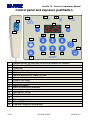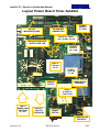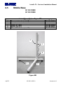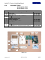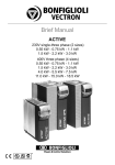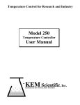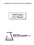
1
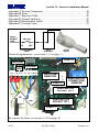
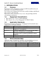
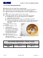
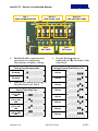
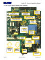
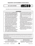
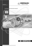
\
IntraOs 70
X-ray Equipment
Service & Installation Manual
Blue X Imaging Srl Via Idiomi 1/8-33 20090 Assago ITALY e-mail [email protected]
IntraOs 70 – Service & Installation Manual
M
Control panel and exposure pushbutton
button
2
1
3
4
1
5
6
7
18
10
11
12
8
16
17
13
14
15
9
1
2
3
4
5
6
7
8
9
10
11
12
13
14
15
16
17
18
2/52
Medical device
evice for emission of ionizing radiation on request
System turned ON and ready
Irradiation
Alarm
Exposure time in s
Manual decrease of exposure time
Manual increase of exposure time
Patient size large
Patient size small
Maxillary incisor
Maxillary canine or premolar
Maxillary molar
Mandibular incisor
Mandibular canine or premolar
Mandibular molar
Bite-wing premolar
Use of digital detector
Radiation exposure pushbutton
69 500 00210
Version 4.0
IntraOs 70 – Service & Installation Manual
Layout Power Board Timer AutoSet
SET-UP
MICROSWITCHES
POWER
SUPPLY
5 V LED
KEYBOARD
CONNECTOR
BACK UP TIMER
TEST POINT & LED
MICROPROCESSOR
WATCH DOG LED
POWER
SUPPLY
24 V LED
FUSE 4
T 200 mA
5 x 20
FUSE 3
T 200 mA
5 x 20
HANDSWITCH
JUMPERS
JUMPER
FUSE 2
FUSE 1
& FUSE 2
T8A 6.3x32
INPUT
MAINS LINE
NEUTRAL
& LIVE
OUTPUT
LINE TO
TUBEHEAD
MAINS
SWITCH
HANDSWITCH
SOCKETS
Version 4.0
69 500 00210
3/52
IntraOs 70 – Service & Installation Manual
M
Blue X Imaging S.r.l.
Via Mario Idiomi 1/8-33
20090 Assago ITALY
tel.+39.0245712171
fax +39.0245703385
e-mail [email protected]
www.bluex.it
IntraOs 70 Dental X-ray Equipment
Service & Installation Manual – English Edition
Version 4.0 March 2008
Printed 30/05/2008 12:11:00
Code 69 500 00210
Blue X Imaging is committed to Total Quality.
Thank you for notifying us any error found in the document.
document
4/52
69 500 00210
Version 4.0
IntraOs 70 – Service & Installation Manual
Table of Contents
1.
2.
3.
4.
5.
6.
INTRODUCTION ................................................................
.................................................. 7
1.1
Purpose..........................................................................................
.......................... 7
1.2
Equipment Classification ..............................................................
.............................. 7
1.3
Applicable Standards ................................................................
.................................... 7
1.4
Environmental Data ................................................................
...................................... 7
1.5
Obligations of the Installer............................................................
............................ 8
1.6
Warning................................................................
......................................................... 8
1.7
Demonstration ................................................................
............................................... 8
TECHNICAL DATA................................................................
.............................................. 9
2.1
System Supply ................................................................
.............................................. 9
2.2
Tube Housing Assembly ...............................................................
............................... 9
2.3
Beam Limiting Device ................................................................
................................ 10
2.4
AutoSet Timer ................................................................
............................................. 10
2.5
Mechanical Suspension System ..................................................
................................
11
2.6
Weights ................................................................
....................................................... 11
ASSEMBLY AND INSTALLATION .................................................
................................
12
3.1
Wall Mounted Systems ...............................................................
............................... 12
3.2
Mobile Systems ................................................................
........................................... 25
MAINTENANCE ................................................................
................................................. 28
4.1
Maintenance of the Wall Support ...............................................
................................
29
4.2
Maintenance of the Extension Arm ............................................
................................
29
4.3
Maintenance of the Folding Arm ................................................
................................
30
4.4
Maintenance of the Tube-Head ...................................................
................................
34
4.5
Maintenance of the Beam Limiting Device ................................ 34
4.6
Maintenance of the Timer ...........................................................
........................... 34
4.7
Checking Filament Pre-Heating Time ........................................
................................
35
4.8
Special Service Functions ...........................................................
........................... 35
MEASUREMENTS................................................................
.............................................. 36
5.1
Line Voltage................................................................
................................................ 36
5.2
Anode Voltage – KVp................................................................
................................. 36
5.3
Anode Current – mA ................................................................
................................... 36
5.4
Exposure Time ................................................................
............................................ 37
5.5
Leakage Radiation ................................................................
...................................... 38
5.6
Earth Resistance ................................................................
.......................................... 38
5.7
Earth Leakage ................................................................
............................................. 39
Spare Parts ............................................................................................
............................ 40
6.1
Tube-Head................................................................
................................................... 40
6.2
Folding Arm ................................................................
................................................ 41
6.3
Extension Arm ................................................................
............................................ 42
6.4
Wall Support ................................................................
............................................... 43
6.5
Mobile Base ................................................................
................................................ 44
6.6
AutoSet Timer ................................................................
............................................. 45
Version 4.0
69 500 00210
5/52
IntraOs 70 – Service & Installation Manual
M
Appendix A System Components ................................................................
................................. 46
Appendix B Icons .........................................................................................
......................... 47
Appendix C Exposure Table ................................................................
......................................... 48
Appendix D Alarm Conditions ................................................................
..................................... 49
Appendix E Identification Labels ................................................................
................................. 50
Appendix F Cooling Curves ................................................................
......................................... 51
INPUT
POWER
LINE
SWITCH
IN
OUT
ELECTRONIC
TIMER
WALL
SUPPORT
X-RAY
HEAD
Electrical requirements: see section 3.1.3 at page 13.
FUSE F4
NEUTRAL
GROUND
LIVE
ZERO OHM
RESISTOR
FUSE F2
HAND-SWITCH
HAND
CONNECTION
JUMPERS
HAND-SWITCH
SWITCH
SOCKET TST2
IN
OUT
HAND-SWITCH
SOCKET TST1
FUSE F1
To connect the timer see section 3.1.10 at page 19.
6/52
69 500 00210
Version 4.0
IntraOs 70 – Service & Installation Manual
1. INTRODUCTION
1.1
Purpose
The IntraOs 70 X-ray Equipment
ipment is design to fulfil the needs for intra-oral
intra
radiography in the general dental practice.
The system can be configured for wall, unit or mobile solutions and different
types of timers and tube-heads.
The features of the system make it easy to use, and grant long useful life
with minimum maintenance.
1.2
•
•
Equipment Classification
IEC: IntraOs 70 is a Class I, type B equipment
FDA: IntraOs 70 is a Class II equipment (21 CFR 872-1800).
1800).
1.3
Applicable Standards
The IntraOs 70 system configurations, all equipped with the AutoSet timer,
comply with the following standards.
IEC 601-1
IEC 601-1-2
IEC 601-1-3
IEC 601-2-7
IEC 601-2-28
21 CFR 1020.30
21 CFR 1020.31
1.4
General requirements for safety
Electromagnetic compatibility
General requirements for radiation protection in
diagnostic X-ray equipment
Particular
lar requirements for the safety of high voltage
generators of diagnostic X-ray
ray generators
Particular requirements for the safety of X-ray
X
source
assemblies and X-ray
ray tube assemblies for medical
diagnosis
Diagnostic x-ray systems
ems and their major components
Radiographic equipment
Environmental Data
Applicable ranges of temperature, humidity, and atmospheric pressure are
reported here below both for operation and transport conditions.
Temperature
Relative Humidity
Pressure
Version 4.0
Ambient
from 10 to 40 °C
from 30 to 75%
from700 to 1060 hPa
69 500 00210
Transport & Storage
from –20 to +50 °C
10 to 90%
from 500 to 1060 hPa
7/52
IntraOs 70 – Service & Installation Manual
M
1.5
Obligations of the Installer
Obligations of the Installer are:
A To make sure that the line voltage specified by the
Manufacturer of the equipment is available and within the
specified range.
B For safety reasons verify that a proper switch is available to disconnect
from line voltage supply when needed during installation.
C Install and test the equipment with due diligence according to the
installation instructions from the Manufacturer.
D To provide the Operator’s Manual to the User.
1.6
Warning
X-ray
ray equipment produce ionising radiation that may be harmful if not
properly controlled. It is therefore recommended that the equipment be
operated by trained personnel only in accordance with existing law.
Even if compliant to specifications of electromagnetic compatibility, it is
recommended not to use the equipment in presence of external
electromagnetic fields, such as those
hose generated by cellular phones, which
might interfere with the electronic circuits of the system.
1.7
Demonstration
In order to use of the system for demonstration purposes radiation emission
has to be inhibited by disconnecting the supply cables to the tube-head
tu
into
the wall support or into the timer.
Cables to be disconnected are those leaving the connection block towards the
tube-head and not those coming in from the timer.
Make sure that the disconnected cables are properly insulated to prevent
undesired contacts with live points.
This task has to be done by trained personnel only to avoid the risk of
electrical shock.
INPUT
POWER
LINE
DISCONNECT
HERE
SWITCH
IN
OUT
ELECTRONIC
TIMER
8/52
WALL
SUPPORT
69 500 00210
X-RAY
HEAD
Version 4.0
IntraOs 70 – Service & Installation Manual
2. TECHNICAL DATA
2.1
System Supply
Line Voltage
Line Voltage
Working Range
Maximum
Line Current
Fuse
Line Frequency
Line resistance
2.2
Tube Housing Assembly
Nominal
Line Voltage
Line Voltage
Working Range
Anode voltage
Anode current
Maximum load
X-ray insert
Focal Spot
Inherent filtration
Duty Cycle
Radiation Leakage
Version 4.0
115 V (from 99 V to 137 V in sub-ranges
sub
depending on tube housing assembly)
230 V (from 198 V to 275 V in sub-ranges
sub
depending on tube housing assembly)
Limited to the working range of the THA:
from108 V to 132 V for type 93 200 01300,
from 207 V to 253 V for type 93 200 01700
8 A at 115 V
5 A at 230 V
8A slow blow at 115 V,
5 A slow blow at 230 V
for two-phase
phase supply or on mobile system,
the second fuse to be activated by jumper cut
50/60 Hz ± 2 Hz
≤ 0.4 Ohm at 115 V,
≤ 0.8 Ohm at 230 V
120 V for type 93 200 01300,
230 V for type 93 200 01700
120 V ± 10% for type 93 200 01300,
230 V ± 10% for type 93 200 01700
70 kVp ± 8% at nominal line voltage
vo
66 kVp ± 8% at nominal line voltage – 10%
74 kVp ± 8% at nominal line voltage+ 10%
7.0 mA ± 15% at at nominal line voltage
5.3 mA ± 15% at nominal line voltage – 10%
8.3 mA ± 15% at nominal line voltage + 10%
70 kVp, 7 mA, 3.2 s
3 electrodes, grid control action
models: OCX/70-G, RFG070
0.8 (EN 60336:1995-04)
> 2.5 mm Al
1/30
< 0.1 mGy/h a 1 m (< 11.5 mR/h a 1 m)
69 500 00210
9/52
IntraOs 70 – Service & Installation Manual
M
2.3
Beam Limiting Device
Round BLD
Rectangular BLD
2.4
Metal body with near-focus
focus section
Focus skin distance (FSD) 8.27”(21 cm)
Rectangular radiation field
size 1.38”x1.81” (3.5x4.6 cm)
AutoSet Timer
Line Voltage
Working Range
Exposure factor
Precision
Exposure factor setting
Irradiation signal
Preheating time
Hand-switch
Overall size
Other features
10/52
Metal cone with near-focus
focus section
Focus skin distance (FSD) 8.27”(21 cm)
Circular radiation field
size 2.35” diameter (6 cm)
115 V ± 15% for type 93 300 60200
230 V ± 15% for type 93 300 60100
Exposure time in s,
18 steps from 0.06 s to 3.2 s (R10 scale)
0.06
0.06
0.06
0.08
0.08
0.08
0.10
0.10
0.10
Time in seconds is converted to number of
mains pulses with 1 pulse precision (20 ms
at 50 Hz, 16.6 ms at 60 Hz.
± 0.02 s or 5% (whichever the greater)
Automatic setting through tooth
toot type
selection and patient size, for use with
traditional film or digital sensor, or manual
setting moving up or down the scale with
plus or minus keys.
Yellow light on hand-switch
switch and on control
panel plus acoustic buzzer
Set at installation (typical value 180 ms)
Hand-switch
switch with 3 m coiled cord,
remote mounting possibility
6” (15 cm) width, 9”½ (24 cm) height, 3”½ (9
cm) depth
Microprocessor controlled functionality
Film speed setting
3 s minimum waiting time
Energy management for cool down time
Optional kit with 33 ft (10 m) cable for
remote hand-switch mounting
69 500 00210
Version 4.0
IntraOs 70 – Service & Installation Manual
2.5
Mechanical Suspension System
Wall Support
Extension arm, length
Folding arm;
useful reach
Mobile Stand
2.6
Weights
Timer
Tube-head:
Round BLD
Rectangular BLD
Folding Arm:
Short Ext. Arm
Medium Ext. Arm
Long Ext. Arm
Extra long Ext. Arm
Wall Support:
Mobile Stand
Version 4.0
4.72” (12 cm) width,
9.45” (24cm) height,
3.54” (9 cm depth)
Short: 17”¾ (45 cm),
medium:27”½ (70 cm),
long 35”½ (90 cm),
extra long 43”¼ (110 cm)
55” (140 cm) with short extension arm
65” (165 cm) with medium extension arm
72”¾ (185 cm) with long extension arm
80” (205 cm) with extra long ext. arm
29” (74 cm) width,
42” (107 cm) height,
24”½ (62 cm) depth
65” (165 cm) total heath with folding arm
3.7 lb (1.7 kg)
14.1 lb (6.4 kg)
0.22 lb (0.1 kg)
0.44 lb (0.2 kg)
15.4 lb (7 kg)
7.7 lb (3.5 kg)
9.3 lb (4.2 kg)
11 lb (5 kg)
12.7 lb (5.8 kg)
2.9 lb (1.3 kg)
55.1 lb (25 kg)
69 500 00210
11/52
IntraOs 70 – Service & Installation Manual
M
3. ASSEMBLY AND INSTALLATION
3.1
Wall Mounted Systems
3.1.1 Unpacking
Unpack the components of the system and check
the following:
A Each item is in good conditions and was not
damaged during transportation.
B All the items for the desired system
configuration are available.
C The line voltage on the labels of timer and
tube-head are corresponding to the existing
local line voltage.
3.1.2 Structural Requirements
The wall support has to be mounted in a convenient position on left or right
side of the chair or on back wall (head of the patient).
The maximum useful reach is of 80” (205 cm) from the wall when
combining a 43”¼ (110 cm) extension arm with a folding arm.
The wall support can be mounted with 2, 4, or 6 bolts, depending on wall
quality.
A Two bolts only (top and bottom central
T1
T2
T3
holes – T2, B2) are used when there is a
solid slim column (e.g. iron mounting) with
weak sides (e.g. wooden wall). Considering
the requested safety factor, each one of the
two bolts has to withstand a load of 5470 N,
comprehensive of a safety factor, i.e. about
1240 lbs or 560 kg. Proper screw to be
selected for a solid connection to the wall.
Classes ISO 8.8 (M 8, M 8x1, M 8x1.25) or
SAE Grade 5 (5/16” 18UNC, 5/16” 24
UNF) are recommended.
B Four bolts, two on top sides (T1, T3) and
two on bottom sides (B1, B3) is the regular
mounting for solid (concrete) wall, but also
on large metal plate. Considering the
B1
B2
B3
requested safety factor, each bolt has to
withstand a load of 2735 N, comprehensive
of a safety factor, i.e. about 620 lbs or 280
12/52
69 500 00210
Version 4.0
IntraOs 70 – Service & Installation Manual
kg. Proper expansion screw to be selected for a solid connection
onnection to the
concrete wall; the permissible load of each screw has to be greater than
308 lbs (about 140 kg).
On solid concrete use heavy duty metal anchors.
On hollow bricks use injection chemical fixing.
C Six bolts, three on top (T1, T2, T3) and three at bottom (B1, B2, B3) are
required when the wall is not solid enough and the load has to be
distributed on more points. Considering the requested safety factor, each
bolt has to withstand a load of 911 N, comprehensive
ehensive of a safety factor,
i.e. about 210 lbs or 95 kg.
In case the wall is not in condition to withstand the indicated load, corrective
actions can be evaluated by adoption of reinforcing plates:
D Large plate to fit vertical supports at 16” distance, withh 4 mounting holes
and one cable opening for the wall mount in the middle.
E In case of a thin (wooden) wall not solid enough, the use of a reinforcing
plate (counter plate) made of iron (2 mm thick) can be the solution.
Make sure that the wall is solid enough
ugh to carry the load.
F The use of two reinforcing iron plates of about 4 times the surface of the
wall support, one by each side of the wall, can help where one single
plate looks not adequate; additional bolts have to be used to keep
together the two plates.
Make sure that the wall is solid enough to carry the load.
Recommended bolts are listed below
Diameter
M 8X1.25
M 8X1
5/16” – 18 UNC
5/16 –24 UNF
Recommended Bolts
Class
ISO 8.8
ISO 8.8
SAE- Grade 5
SAE- Grade 5
Core Section mm
36.6
39.2
33.8
37.41
2
INSUFFICIENT WALL OR HARDWARE STRENGHT
MAY CAUSE THE WALL MOUNT TO PULL OUT FROM
THE WALL AND THE FULL SYSTEM TO FALL ON TO
THE PATIENT OR THE OPERATOR CAUSING
INJURIES.
3.1.3 Electrical Requirements
The power line cable must be connected to the input terminals
inals (IN) of the
timer to supply the timer itself and to make available power for the X-ray
X
head at the output terminals (OUT), upon request by the operator (via the
hand switch).
Power to the X-ray
ray head is thus controlled by the timer (SWITCH).
Version 4.0
69 500 00210
13/52
IntraOs 70 – Service & Installation Manual
M
The X-ray
y head is connected to the output terminals of the timer (OUT)
through the connecting block in the wall support.
INPUT
POWER
LINE
SWITCH
IN
OUT
ELECTRONIC
TIMER
WALL
SUPPORT
X-RAY
RAY
HEAD
Cabling (2 poles plus ground) to connect the power line to the timer and the
timer to the wall support is not provided and has to be procured.
procured Cable with
large section conductors keeps to minimum the wire resistance and the
relevant voltage drop.
Wire Type
AWG 16
AWG 14
Square Section mm
1.35
2.11
2
Resistance Ohm/m
2x0.015
2x0.0094
The hand-switch too can be mounted far from the timer, provided the patient
is in view and the sound of the buzzer can be heard.
3.1.4 Mounting and Connecting Sequence
A Mount the Wall Support
B Mount the Timer
C Mount the Extension Arm
D Mount the Folding/Simple Arm
E Connect the Wall Support
F Connect the Timer
G Connect the hand-Switch
H Optional Remote hand-Switch
I Mount and connect the Tube-head
J Mount the Beam Limiting Device
K Final Tuning and Set-Up
14/52
69 500 00210
Version 4.0
IntraOs 70 – Service & Installation Manual
3.1.5 Mounting the Wall Support
A Remove the plastic cover
unscrewing the screws under the
logo label.
B Use the Wall Support plate or a
template to mark the holes on the
wall. Please note that the timer
can be mounted close to the Wall
Support on the right side or in a
remote position. Cabling should
have been laid out accordingly.
C Make the holes in the wall according to
D
E
F
G
the applicable type of mounting:
a Two bolts,
b Four bolts,
c Six bolts,
d With or without reinforcing plate.
Slide the logo-strip out from the plastic
cover to access the screws and remove it
from the metal frame.
Mount the metal frame on the wall using
proper heavy-duty metal anchors and
make sure that the power cable enters
from behind.
Secure it to the wall ensuring it is level.
Improper levelling might cause the arm
to move and swing out of
position.
Perform wire connection and
final set-up complying with
recommended sequence of actions
reported in the following.
Version 4.0
69 500 00210
T1
T2
T3
B1
B2
B3
15/52
IntraOs 70 – Service & Installation Manual
M
3.1.6 Mounting the Timer
A Use the mounting plate or the
template to mark the holes on
the wall.
B Slide the logo-strip out from
the plastic cover to access the
screws and remove the plastic
cover from the plastic frame.
C Drill the four holes in the wall
and secure the timer making
sure it is level. Cabling should
have been laid out in
accordance to mounting
requirements.
D Perform wire connection and
final set-up complying with
recommended sequence of
actions reported in the
following.
3.1.7 Mounting the Extension Arm
A Unpack the extension arm and check for completeness of parts.
B Cut, but do not remove, the string to be used later on to pull the cable
from the Folding/Simple Arm through the Extension Arm to the Wall
Support.
C Lightly grease the support tube at base of the extension arm and insert at
top of wall mount.
D Insert, but without tightening, the locking and the friction screws.
16/52
69 500 00210
Version 4.0
IntraOs 70 – Service & Installation Manual
3.1.8
Mounting the Folding Arm
WARNING.
THE SPRINGS IN THE FOLDING ARM
MAY CAUSE INJURY TO THE
INSTALLER AS WELL AS DAMAGE
TO THE ARM ITSELF IF NOT
HANDLED PROPERLY.
DO NOT REMOVE BINDING UNTIL
WHEN NECESSARY AS INDICATED IN
THE INSTRUCTIONS BELOW.
A Slide the blocking ring onto the support
tube at base of the arm.
B Light grease the mounting pin at base of
Folding Arm.
C Secure the driving string to the end of the
electrical cable of the Folding Arm.
D Pull the other end of the string to drive
the electrical cable of the Folding Arm
through Extension Arm out into Wall
Mount.
E Hold Folding Arm sections together and
carefully remove binding allowing the
arm sections to open slowly, away from
people.
F Perform wire connection (into the wall
Support) and final set-up complying with
recommended sequence of actions
reported in the following.
SAFETY
STRIP
WARNING.
NEVER
CONNECT
THE CABLE
OF THE
FOLDING
ARM
DIRECTLY
TO
MAINS
LINE.
Version 4.0
69 500 00210
17/52
IntraOs 70 – Service & Installation Manual
M
3.1.9
Connecting the Wall Support
EXTENSION
ARM
TO
FOLDING
ARM
FROM
TIMER
GROUND
CONNECTIONS
ON WALL
PLATE
WALL SUPPORT CONNECTIONS
A Connect the three wires from the Timer (additional cable) to the terminal
block and to the Folding/Simple Arm (Tube-head)
head) as reported in the next
figure.
B Connect the ground cable on the Wall Support to the blocking bolt on
the extension arm
18/52
69 500 00210
Version 4.0
IntraOs 70 – Service & Installation Manual
3.1.10 Connecting the Timer
A Turn-off the line voltage supply line.
FUSE F4
NEUTRAL
GROUND
LIVE
ZERO OHM
RESITOR
FUSE F2
HAND-SWITCH
HAND
CONNECTION
JUMPERS
HAND-SWITCH
SWITCH
SOCKET TST2
IN
OUT
HAND-SWITCH
SWITCH
SOCKET
T TST1
FUSE F1
B Connect the three wires from the line voltage supply to the
terminal block (IN on the left) but do not connect any
outgoing wire (OUT on the right) to Wall Support.
C Make sure that the “live” connector is the “hot” one:
a Connect an AC voltmeter or a test light between the block terminal
“live in” and “ground”.
b Turn line voltage supply “ON”. If full line voltage is measured (test
(
lamp lights) the wiring is correct. If not turn line voltage supply
“OFF”,
”, reverse “live in” and “neutral in” wires and repeat the
measurement; eventually the full line voltage should be read
between “line” and “ground” (test lamp lights).
c Make sure no voltage is read between “neutral in” and “ground”; if
not check line voltage distribution.
D Test the timer for full functionality keeping the output cables
disconnected so that power is not provided to the load.
Version 4.0
69 500 00210
19/52
IntraOs 70 – Service & Installation Manual
M
E Connect the load.
LIVE IN
NEUTRAL OUT
Turn OFF the line
voltage supply line,
LIVE OUT
NEUTRAL IN
GROUND
Connect the three
wires of additional
FROM
LINE
TO
cable outgoing to the
VOLTAGE
FOLDING
SUPPLY
ARM
Folding Arm (Wall
Support).
INPUT
OUTPUT
Live and neutral wires
to
TIMER CONNECTIONS
the folding arm (tubehead) can be interchanged.
Fuse
F1
F2
F3, F4
Table of Fuses for Timer AutoSet
115 V
230 V
T8 A 6.3x32
T5 A 5x20
T8 A 6.3x32
T5 A 5x20
T200 mA 5x20
T200 mA 5x20
3.1.11 Connect the Hand-Switch
The hand-switch
switch is provided with a 3 m coiled cord the terminations can be
plugged in the lower left corner
ner of the board, either externally (connector
TST1) or internally to the timer (connector TST2).
Jumpers are available to activate properly the hand-switch
switch connection:
Position TST1 for TST1, TST2 for TST2, TST1/2 for both.
3.1.12 Optional Remote Hand-Switch
The hand-switch can be remotely mounted using the optional kit made of a
remote box (wall holder) and connection cable.
• The wall holder (remote box) has a hook to hold the hand-switch
hand
and a
plug below where to connect the coiled cable.
• A cable 10 m long is provided with a plug on one side, to connect to the
socket on the timer, and free wires on the other side, to be able to place it
conveniently around the room, and eventually to connect it to the block
into the wall holder (remote box).
The connection of the wires
is here indicated.
The wires of the switch are
number 3 and 4 (those in the
middle of the connector).
20/52
69 500 00210
Version 4.0
IntraOs 70 – Service & Installation Manual
3.1.13 Mounting and Connecting the Tube-Head
A Remove retaining screws and cover plate on inner side of terminal pole
(handgrip) of Folding/Simple Arm at tube-head side.
B Unscrew and slide out the U shaped retaining clip .
C Slightly lubricate the outer pin of the connecting socket of the tube-head.
tube
D Slide the connecting socket into the terminal pole of the Folding/Simple
Arm.
E Put back the U shaped retainingg clip making sure it has entered the
specific slot on the outer pin of the connecting socket and tighten the
locking screw.
F Put back the cover plate and block it with the four retaining screws.
3.1.14 Mounting the Beam Limiting Device
A Mount the beam limiting device on the tube-head
head and lock it close with a
clock-wise rotation.
Version 4.0
69 500 00210
21/52
IntraOs 70 – Service & Installation Manual
M
3.1.15 Final Tuning and Set-Up
A
B
C
D
E
F
G
H
I
J
K
Remove the line voltage fuse(s) from the timer
Put back the cover plate on the folding/simple arm (tube--head side)
Tighten locking screw and tune friction screw in Extension Arm.
Tune friction screw on the folding arm for rotation around the vertical
axis.
Make sure the Timer switch is in the “off” position.
Set the dip switches SW2 as indicated in the following to define:
a Enable/disable correction of exposure time to compensate
nsate
fluctuations of line voltage.
b Indicate the nominal line voltage of the tube-head
head (see label).
c Set the pre-heating time according to type of X-ray
ray insert used in the
tube-head assembly; the measured value is marked in
n front of the
tube-head;
Put back the line voltage
fuse(s).
Put back all plastic covers
and logo strips.
Connect the system to the
line voltage by switching the
general line voltage switch
on and/or plug the power
cord into the wall socket.
Switch the timer “on”.
The system is now ready for
Functional Check as
described in the Operator’s Manual.
PRE-HEATING TIME SETTING - TYPICAL VALUES
Type of insert
Pre-Heating
Time
22/52
OCX/70-G
RF8G070
180 ms
160 ms
69 500 00210
Version 4.0
IntraOs 70 – Service & Installation Manual
DIP 1
DOSE COMPENSATION
DIP 2-3
TUBE-HEAD TYPE
DIP 4
NOT USED
•
Enable/disable exposure time
correction to compensate
fluctuations of mains voltage.
•
DIP 8
NOT USED
•
dip 1
Setting Dose Compensation
Set pre-heating
heating time as
indicated on label in front of the
tube-head
dip 5 – dip 6 – dip 7
Setting Filament Pre-Heating
Pre
Time
Disabled
100 ms
Enabled
120 ms
Indicate the nominal voltage of
the tube-head (see label).
dip 2 – dip 3
Setting Tube-Head Type
140 ms
160 ms
110 or 220
VAC
180 ms
115 or 230
VAC
200 ms
120 or 240
VAC
220 ms
125 or 250
VAC
240 ms
Version 4.0
DIP 5-6-7
PRE-HEATING TIMES
PRE
69 500 00210
23/52
IntraOs 70 – Service & Installation Manual
M
3.1.16 Layout Power Board Timer AutoSet
SET-UP
MICROSWITCHES
POWER
SUPPLY
5 V LED
KEYBOARD
CONNECTOR
BACK UP TIMER
TEST POINT & LED
MICROPROCESSOR
WATCH DOG LED
POWER
SUPPLY
24 V LED
FUSE 4
T 200 mA
5 x 20
FUSE 3
T 200 mA
5 x 20
HANDSWITCH
JUMPERS
JUMPER
FUSE 2
FUSE 1
& FUSE 2
T8A 6.3x32
INPUT
MAINS LINE
NEUTRAL
& LIVE
OUTPUT
LINE TO
TUBEHEAD
MAINS
SWITCH
HANDSWITCH
SOCKETS
24/52
69 500 00210
Version 4.0
IntraOs 70 – Service & Installation Manual
3.2
Mobile Systems
3.2.1 Unpacking
Unpack the components of the system and
check the following:
A Each item is in good conditions and was
not damaged during transportation.
B All the items for the desired system
configuration are available.
C The line voltage on the labels of timer
and tube-head are corresponding to the
existing local line voltage.
3.2.2 Room Preparation
Make sure that a wall socket is available
close to the dental chair in reach of the
mobile X-ray equipment to be connected.
Such a socket has to be provided with a
ground connector to the protective earth
point of the room. For the line voltage
supply to the wall socket it is recommended
the use of a cable with large section
conductors to keep to minimum the cable
resistance and the relevant voltage drop.
Wire Type
AWG 16
AWG 14
Version 4.0
Square Section mm
1.35
2.11
69 500 00210
2
Resistance Ohm/m
2x0.015
2x0.0094
25/52
IntraOs 70 – Service & Installation Manual
M
3.2.3 Mounting and Connecting Sequence
The recommended sequence to mount and
connect system modules is listed here below.
A Assembly the Mobile Stand.
B Mount the Timer.
C Mount the Suspension Arm.
D Connect the Line voltage Cable.
E Connect the Timer.
F Mount and connect the Tube-head.
G Mount the Beam Limiting Device.
H Final Tuning and Set-Up.
3.2.4 Assembling the Mobile Stand
The following sequence to be followed.
A Put together the base elements and tighten
screw and washer.
B Mount the column (timer plate externally to
the long legs – see picture) and tighten it
with the screw and washer from below.
C Mount the front wheels and rear wheels
with brake.
D Mount the manoeuvring handles.
E Connect the plug on the line voltage cable.
3.2.5 Mounting the Timer
A Refer to section 0 at page 18.
B The zero Ohm resistor R51
close to fuse F2 has to be cut
for systems cord connected to
the mains.
3.2.6 Mounting the Suspension Arm
Refer to section 3.1.8 at page 17.
26/52
69 500 00210
Version 4.0
IntraOs 70 – Service & Installation Manual
3.2.7 Connecting the Line voltage Cable
A The line voltage cable for the mobile unit is provided with plug.
B The grounding wire of the main cable has to be blocked (first) to the
grounding provision (common
common bolt for bonding and grounding)
grounding using
nut and lock-washer.
C The grounding wire for the
he timer is the placed on the common bolt for
bonding and grounding and blocked (second) with nut and lock-washer.
D Connect the grounding cable for the timer to
GROUND PROVISION
the ground provision on the terminal block of
ON MOBILE FRAME
the timer and the two line
GROUND
wires from the mains cable to WIRE INPUT
the input point for live and
neutral connections.
3.2.8 Connecting the Timer
For the connection of the output
cable to the timer please refer to
section 0 at page 18.
N
L
N
L
NEUTRAL IN
GROUND
POINTS
3.2.9
Activation of
LIVE IN
Fuse 2
Units provided with supply cord
and plug must be equipped with fuses on
both line phases. The activation on the
second fuse is done by cutting the Jumper
Fuse 2 (zero Ohm resistor) close to Fuse
F2. See position on layout in section
3.1.16 at page 24.
INPUT
FROM
LINE
VOLTAGE
SUPPLY
OUTPUT
TO
FOLDING
ARM
TIMER CONNECTIONS MOBILE
3.2.10 Connecting the Tube-Head
Refer to section 3.1.11 at page 20.
3.2.11 Mounting the Beam Limiting Device
Refer to section 3.1.14 at page 21.
3.2.12 Final Tuning and Set-Up
Refer to section 3.1.15 at page 22.
Version 4.0
69 500 00210
27/52
IntraOs 70 – Service & Installation Manual
M
4. MAINTENANCE
It is the responsibility of the User to maintain the IntraOs 70 equipment in
compliance with the performance standard.
Failure of the User to properly maintain the equipment may relieve the
Manufacturer, or its Agent, from responsibility for any injury, damage or
non compliance which may result.
The suggested frequency for checks of the IntraOs 70 system if of at least
once every 12 months, with a specific maintenance of the folding arm every
24 months, performed by qualified personnel.
Any defect or malfunction should be corrected immediately by qualified
quali
personnel with adequate training.
WARNING. ANY DEFECTIVE ITEM AFFECTING A
SAFE USE MUST BE REPAIRED OR REPLACED
Only original certified components and spare parts must be used for repairs
or replacements.
Correction of damages to the identification
on labels to be handled with the
Manufacturer.
Any defect or non-compliance
compliance must be reported promptly to the
Manufacturer or to its Local Agent.
ALWAYS DISCONNECT THE SYSTEM FROM THE LINE
VOLTAGE SUPPLY USING THE GENERAL LINE VOLTAGE
SWITCH FOR THE ROOM WHERE
HERE THE EQUIPMENT IS
I
LOCATED BEFORE PERFORMING
RMING ANY MAINTENANCE
MAINTENANC
ACTIVITY.
AVOID USING LIQUID OR SPRAY DETERGENTS
WHICH MAY ENTER INTO THE EQUIPMENT AND
CAUSE CORROSION.
AVOID THE USE OF SOLVENTS OR CORROSIVE
DETERGENTS WHICH CAN DAMAGE PAINTED
SURFACES AND PLASTIC COVERS.
28/52
69 500 00210
Version 4.0
IntraOs 70 – Service & Installation Manual
4.1
Maintenance of the Wall
Support
FRICTION
SCREW
A Remove the cover and verify that the mounting
is closely connected to the wall and stays firm
and steady during various movements of the
system.
B Verify that the ground cable of the wall support
is properly connected to the wall plate and to
the blocking bolt on the extension arm.
C Check friction during rotation of Extension
Arm and adjust relevant screw if needed.
D Verify that the technical label with
identification data outside the plastic cover at
bottom is in place and is readable.
4.2
Maintenance of the Extension Arm
A Slide partially out
the extension arm
from wall mount,
inspect for wear of
the joint and
lubricate for smooth
rotation.
B Check friction
during rotation of
Folding Arm and
adjust relevant screw
if needed.
C Verify that the
technical label with
identification data is
in place and is
readable.
Version 4.0
FRICTION
SCREW
69 500 00210
29/52
IntraOs 70 – Service & Installation Manual
M
4.3
Maintenance of the Folding Arm
Specifically for the folding arm inspect for wear of pins and levers at least
every 24 months, in case of normal usee (about 6000 cycles). Replace the
worn out parts or the arm itself if it appears damaged.
ARM SECOND
SECTION
ARM FIRST
SECTION
MINIMUM
CLEARANCE
b
a) BASIC PIN
b) BRASS BUSHING
a
c) SAFETY CLAMP
CLA
d) SIDE HOLDER
d
c
PARTS OF ARTICULATED JOINT
Maintenance can be performed with the arm mounted on the extension arm
or on the mobile stand.
A Disconnect the tube housing assembly
bly keeping the arm fully open to
avoid the risk of injuries (fig.1) .
B Remove the snap-out caps of the first arm section, the blocking screws
of the pins, then the metal cover by pushing the pins out paying
attention to supporting the arm (fig. 2 and fig. 3).
30/52
69 500 00210
Version 4.0
IntraOs 70 – Service & Installation Manual
Fig. 1
Fig. 2
Fig. 3
Fig. 6
BENT ARM
(IN SHADE)
INDICATES
WEARING OUT
OF BASIC PIN
Fig. 4
Fig. 5
Fig. 8
Version 4.0
Fig. 7
Fig. 9
69 500 00210
31/52
IntraOs 70 – Service & Installation Manual
M
Fig. 10
Fig. 11
Fig. 12
Fig. 13
Fig. 14
Fig. 15
Fig. 17
32/52
69 500 00210
Fig. 16
Fig. 18
Version 4.0
IntraOs 70 – Service & Installation Manual
C Be careful not to pinch fingers between the two sections
ns of the arm
while manoeuvring (fig. 4).
D In the second section of the arm remove the two snap-out
out caps on the
E
F
G
H
I
J
K
L
M
tube-head
head side and the pin in order to raise the metal cover and tune
friction (fig. 10) and spring (fig. 11). In case of removal, beware that
the metal cover of the second section is different.
Inspect the main joint at the base of the arm (fig. 8)) for wearing out of
pin and levers. A clearance lower than 3 mm of the block holding the
two levers from the body of the first
3 mm
arm (fig. 7) indicates that the “basic
MINIMUM
pin” of the articulated joint is
wearing out, and must be replaced.
Also a parking position with the first
section of the arm not standing
vertical (fig. 4) but bent to some 5
degrees or more reveals that the basic
CLEARANCE
pin is wearing out. To replace the pin
CHECK
of the articulated joint (fig. 8)
proceed as follows:
a Loosen the friction screw (fig. 10) and release the spring by
rotating the spring cap (fig. 11) with a round tool of 4 mm diameter
(the base of a drill is fine) until zero pressure on the basic pin (fig.
(
12, about 1 cm free thread left);
b Keeping the first arm vertical, push the brass bushing out (fig. 13)
and extract the supporting parts (round tool size 10 mm diameter);
diameter)
c Disassemble the parts of the joint and replace the basic pin;
pin
d Tension the spring as needed by screwing the spring cap to the
desired distance (fig. 11, about 5 cm free thread left);
left)
Lubricate moving parts (fig. 17 and fig. 18) and the three pins to block
the metal covers before their insertion.
Mount the metal covers provisionally, with friction screws loosen
Mount the tube-head
head and secure it with the holding fork (fig.
(
1)
Verify
ify proper balancing and in case tune tension of springs.
Tune the friction screws of the two arms.
Block tight the screws of metal covers and place the snap-out
snap
caps.
Slide partially out the Arm from the Extension Arm, inspect for wear of
the vertical joint and lubricate for smooth rotation.
Verify that the label with identification data is in place and is readable.
Version 4.0
69 500 00210
33/52
IntraOs 70 – Service & Installation Manual
M
4.4
Maintenance of the Tube-Head
A Inspect for damage/wear to the X-ray tube-head
head and support system.
B Inspect for oil leakage. Replace tube-head if necessary.
C Check for position
D
E
F
G
stability. Adjust
friction for rotation
around the horizontal
axis if necessary.
FRICTION
Check that electrical
SCREW
cables are correctly
twisted and not
damaged or wear out.
Verify that the
FRICTION
technical label with
SCREW
identification data is
in place and is
readable.
Dismount the tubehead from the arm and lubricate the pin for
smooth rotation. Warning: remove the tubehead with the arm completely open to avoid
the risk of injuries.
Check the U shaped retaining clip and replace
if wear. Do not mount the tube-head until all
checks of the suspension system are
completed.
4.5
FRICTION
SCREW
Maintenance of the Beam Limiting Device
A Verify that the collimator is properly mounted and, in case, lock it
firmly closed.
B Verify that the internal cone is not damaged. Replace the collimator if
necessary.
C Verify that the technical label with identification data is in place and is
readable.
4.6
Maintenance of the Timer
A Inspect the panel for damages on the surface.
B Inspect the cable of the exposure switch for wear.
C Check that all lights (except the yellow one) are working when the
system is switched on.
D Perform a Functional Check as described in the Operator’s Manual.
This check includes verification of: a) yellow light, b) buzzer, c) alarm
34/52
69 500 00210
Version 4.0
IntraOs 70 – Service & Installation Manual
for “Exposure push button pressed at power on”, d) alarm for
“Exposure stopped by the operator”.
E Verify that the fuses mounted comply with what specified in the table
below.
F Verify that the technical label with identification data is in place and is
readable.
Fuse
F1
F2
F3, F4
4.7
Table of Fuses for Timer AutoSet
et
115 V
230 V
T8 A 6.3x32
T5 A 5x20
T8 A 6.3x32
T5 A 5x20
T200 mA 5x20
T200 mA 5x20
Checking Filament Pre-Heating
eating Time
During the life of the system the
wearing out of the filament may result
in a different pre-heating time (PHT).
The value set at installation needs
therefore to be verified and in case
corrected.
A At a fixed distance measure the Xray dose for exposure of 2.0 s
(nominal irradiation of 100 pulses
at 50 Hz, 120 at 60 Hz).
B At same distance measure the dose for exposure of 0.2 s
(nominal irradiation of 10 pulses at 50 Hz, 12 at 60 Hz).
C If dose at 0.2 s is 1/10 of dose at 2 s, the value set for PHT is fine.
D If dose at 0.2 s is lower than 1/10 of the dose at 2 s, PHT has to be
increased. Proceed at steps of 20 ms until fine.
E If dose at 0.2 s is higher than 1/10 of the dose at 2 s, PHT has to be
reduced. Proceed at steps of 20 ms until fine.
4.8
Special Service
Functions
A Digital Volt Meter. This function allows the
user to display the line voltage level (for
example 224 V in the side picture).
a Enter this function by switching the system
“on” while pressing at the same time the
, the , and the
keys.
b Exit by switching the system off.
Version 4.0
69 500 00210
35/52
IntraOs 70 – Service & Installation Manual
M
B Test of Control Panel. This function is intended to test lights, buttons,
and segments of numerical display on the control panel.
a Enter this function by switching the system “ON”” while pressing at
the same time the , the , and the adult
keys.
b By pressing the
or
keys all segments of the numerical
display are scanned.
c By pressing the X-ray pushbutton the “rAY” message is
displayed.
d By pressing each button on the panel, the corresponding lamp is
turned “ON”; a second pressure would turn it “OFF”.
e At the last button pressed the system automatically exit this
function.
WARNING: Do not press the X-ray
ray pushbutton as last
button twice; the second time the timer becomes active
and radiation is emitted.
5. MEASUREMENTS
All measurements to be done with the equipment supplied at nominal line
voltage with specified line resistance (see section 2.2 att page 9). The
tolerances on the measured values have to take into account the precision of
the each measurement instrument. Measurements have to be done by
trained personnel only to avoid the risk of electrical shock.
5.1
Line Voltage
The Line voltage can be measured using a Volt Meter for Alternate Current
within the proper range. A service function can be activated on the AutoSet
timer to display the current line voltage (see section 4.8 of this Manual).
5.2
Anode Voltage – KVp
The kVp level is the actual peak value of the Anode voltage which
stabilizes once the preheating time of the filament has elapsed (in about
0.2 s) and the high voltage transformer is actually loaded. The kVp level
can be measured with a non-invasive
invasive kVp meter placed in front of the BLD
following the instructions in the user manual of the instrument. A correct
measure can be done with an exposure time of 500 ms or more having
introduced a delay of the reading instrument of about 300 ms to allow the
voltage level to stabilize after the pre-heating
heating time has elapsed.
5.3
Anode Current – mA
WARNING. To prevent high voltage shock make sure the system
is disconnected from the power supply when connections
ctions to the
measurement points are performed. Electric discharge might
36/52
69 500 00210
Version 4.0
IntraOs 70 – Service & Installation Manual
occur in case of improper operation
The Anode current in mA is the actual
A1
average value of the tube current which
raises when the filament has warmedup, after the preheating time has
elapsed.
Remove the back cover of the tubehead, disconnect the jumper A1-A2 and
replace it with a precision resistor of
A2
1000 Ohm.
The anode current can be read with a
DC voltmeter connected to points A1 and A2, with the 1 V corresponding
to 1 mA.
Afterr the measurement disconnect the 1000 Ohm resistor and put back the
jumper.
5.4
Exposure Time
The actual exposure (loading) time is “determined as the time interval
between the instant when the tube current first rises above the 25% of its
maximum value and the
he instant when it finally falls below the same value”.
In order to assure the requested exposure time (irradiation), the pre-heating
pre
time of the used insert, set-up
up at installation, is automatically taken into
consideration by the microprocessor.
The actual switch-on time (SOT) of the tube-head
head assembly is therefore the
sum of the filament pre-heating
heating time (PHT) and of the requested exposure
time (RET).
SOT = PHT + RET
During filament pre-heating radiation is not emitted.
The measure of the exposure time
ime can be correctly measured with kVp &
Time meters with the ability to trigger when the kV level reaches 75% of its
maximum.
Exposure time can also be measured after having connected a precision
resistor of 1000 Ohm between points A1 and A2 on the small circuit board
on the back of the tube-head,
head, by monitoring the voltage across it (tube
current) with an oscilloscope, and counting the number of pulses in the time
interval, as per above definition.
When the compensation function to correct the effects of line fluctuations
on the emitted X-ray
ray dose is activated, the requested exposure time is
corrected in order to assure dose consistency.
When the actual line voltage is lower than the nominal line voltage, the
actual exposure time is increased.
Version 4.0
69 500 00210
37/52
IntraOs 70 – Service & Installation Manual
M
When the actual
tual line voltage is higher than the nominal line voltage, the
actual exposure time is decreased.
Do disable the compensation function (dip switch number 1 of SW2 moved
to OFF position) to verify exposure time accuracy.
This is not necessary in case a meter
er with the ability to trigger on 75% of
the kVp level and the value read should be compared with the indication
given by the timer for 3 seconds after the exposure (refer to the Operator’s
Manual to activate the function to display the actual exposure time
tim after
compensation).
5.5
Leakage Radiation
The value of leakage radiation of the X-ray tube assembly is measured at
1 m distance taking into account the energy provided in 1 hour. In case the
measurement is performed at a distance different from 1 m, the value
val has to
be properly corrected.
The applicable technique factors are of 70 kV and 7 mA. The point of
maximum leakage has to be considered, excluding the direction of the
primary beam. The duty cycle factor as reported in sections 2.2 has also to
be taken into account for the computation of the actual dose rate.
In case for example a measure is done at 50 cm distance from the source
with an exposure of 1 s, the following computations have to be performed:
• A duty cycle of 1/30 means
ans maximum of 1 s exposure every 30 s, i.e.
120 s per hour.
• Dose at 100 cm is computed taking into account the inverse square law,
i.e. at twice the distance the dose intensity is reduced to one quarter.
D1h100cm = D1s50cm * 120 * (50/100)2 = D1s50cm * 30
3
where: D1s50cm is the dose measured at 50 cm with 1 s exposure
and D1h100cm is the dose computed at 1 m distance for the energy of 1
hour.
5.6
Earth Resistance
The measurement of the earth resistance to be done after having
disconnected the system for the power supply line.
Using a voltage generator of not more than 6 V, 50/60 Hz, a current of 25 A
is applied from 5 s to 10 s through the earth terminal to any metal part
which can be in touch to the patient/operator.
The voltage drop is then measured and the earth resistance computed.
The system complies for values lower than 0,1 Ω (extended to 0,2 Ω in case
the supply cable cannot be disconnected like in the cases of permanent
installations).
38/52
69 500 00210
Version 4.0
IntraOs 70 – Service & Installation Manual
5.7
Earth Leakage
Connect the Timer to the
measuring circuit as
shown in the figure
(R1=10 kΩ ± 5%, R2=1
kΩ ± 1%,
C1=0,015 µF ±5%)
A Set the input supply
voltage (Vp) equal
to 110% of the
nominal supply
voltage.
B Connect a voltmeter
(Vx with 1 MOhm
input impedance) to
the indicated points
C Switch the Timer “ON”
D Make two measures
sures in Normal Conditions (NC with S1 “ON”)
S5 “ON”: live and neutral conductors in normal condition.
S5 “OFF”: swap of live and neutral conductors.
E Make two measures in Single Fault Condition (SFC with S1 “OFF”).
S5 “ON”: live and neutral conductors in normal condition.
S5 “OFF”: swap of live and neutral conductors.
Please note that 1V equals to 1mA.
Make sure values of leakage currents fall within the limits shown in the
table below.
LIMIT OF EARTH LEAKAGE
GE CURRENT
Normal
Single Fault
Type Of Device
Condition
Condition
(S1 “ON”)
(S1 “OFF”).
X-ray Equipment permanently
connected to line voltage
Mobile X-ray Equipment
Version 4.0
5 mA
2,5 mA
69 500 00210
10 mA
5 mA
39/52
IntraOs 70 – Service & Installation Manual
M
6. Spare Parts
6.1
Tube-Head
93 200 01700: G 230 V without BLD
93 200 01300: G 120 V without BLD
Item
A
B
C
D
E
F
G
List of Spare Parts – Figure TH
Description
Rear and Front Cover
Round Beam Limiting Device, FFD 21 cm
Output Field 6 cm diameter
Code
76 190 25110
91 300 00020
rectangular Beam Limiting Device, FFD 21 cm
Output Field 3.5x4.6 cm
91 300 00040
Side cap tube-head holder
Coupling with Concentric Pin
for SN lower than TK0501
Friction Ring for tube-head with screws
Wave Suppressor
76 190 25120
76 190 25241
76 190 25240
76 190 25450
76 190 25600
A
G
C
B
F
E
D
Figure TH
40/52
69 500 00210
Version 4.0
IntraOs 70 – Service & Installation Manual
6.2
Folding Arm
93 100 12010: for Wall Mount
Item
A
B
C
D
E
F
G
H
I
L
List of Spare Parts - Figure FA
Description
Tube head support for folding arm
for SN lower than FA0501
0501
Cover Plate Tube-Head Holder
Arm Cover Extension Side
Arm Cover Tube-Head Side
Retaining Clip With Screw
Cable 2.8 m With Concentric Connector
for SN lower than FA0501
0501
Ring Spacer D 25 With Hole
Snap Out Cap (set of 8)
Friction Screw M6x10 For Arm (set of 2)
Basic pin and seeger rings
D
Code
76 190 25251
76 190 25250
76 190 25130
76 190 25140
76 190 25150
76 190 25270
76 190 25431
76 190 25430
76 190 25460
76 190 25160
76 190 25340
76 500 30010
A
H
I
E
B
C
G
L
F
Figure FA
Version 4.0
69 500 00210
41/52
IntraOs 70 – Service & Installation Manual
M
6.3
Extension Arm
93 100 17100 – 45 cm
93 100 17200 – 70 cm
93 100 17300 – 90 cm
93 100 17400 – 110 cm
Item
A
B
C
List of Spare Parts – Figure EA
Description
Large Ring Spacer D35
Snap out Cap D25 (set of 8)
Friction Screw Brass Cap M6x10 (set of 3)
Friction Screw Brass Cap M8x10 (set of 3)
A
Code
76 190 25470
76 190 25180
76 190 25331
76 190 25332
B
Figure EA
42/52
69 500 00210
Version 4.0
IntraOs 70 – Service & Installation Manual
6.4
Wall Support
93 100 11000
Item
A
B
List of Spare Parts - Figure WS
Description
Plastic Cover Wall Mount
Logo Strip Blue X
Code
76 190 25190
76 190 25200
A
B
Figure WS
Version 4.0
69 500 00210
43/52
IntraOs 70 – Service & Installation Manual
M
6.5
Mobile Base
93 100 20080
93 100 20090
Item
A
B
C
D
E
List of Spare Parts – Figure MB
Description
Transport Handle (set of 2)
Cable Holder With Strain Relief
Hook For Cable
Wheel (set of 2)
Wheel With Brake (set of 2)
Code
76 190 25280
76 190 25300
76 190 25290
76 190 25410
76 190 25420
A
C
B
D
E
Figure MB
44/52
69 500 00210
Version 4.0
IntraOs 70 – Service & Installation Manual
6.6
AutoSet Timer
93 300 60100: 230 V
93 300 60200: 115 V
Item
A
B
C
D
E
F
G
H
I
J1
J2
List of Spare Parts – Figure AU
Description
Code
76 190 25220
76 190 25230
76 190 25310
76 190 25510
76 190 25511
76 190 25530
76 190 25550
76 190 25590
76 190 25580
76 190 25210
76 190 25640
76 190 25641
76 190 25630
Front Cover
Mounting Plate
Mounting Columns
230V Power Control Board With Triac
115V Power Control Board With Triac
Keyboard Control Panel
AutoSet Membrane
Hand Switch Without Cable
Coiled Cable
Logo Strip IntraOs 70
230V Fuse F1/F2 T5A 250V 5x20 (set of 10)
115V Fuse F1/F2 T8A 250V 6.3x32 (set of 10)
Fuse F3/F4 T200mA 250 V 5x20 (set of 10)
B
C
E
D
A
F
I
G
H
Figure AU
Version 4.0
69 500 00210
45/52
IntraOs 70 – Service & Installation Manual
M
Appendix A
System Components
Article
System Component
46/52
Type Code
Catalogue Number
Wall Support
93 100 11000
Extension Arm 45 cm
Extension Arm 70 cm
Extension Arm 90 cm
Extension Arm 110 cm
93 100 17100
93 100 17200
93 100 17300
93 100 17400
Folding Arm
93 100 12010
Tube Head G 120 V
Tube Head G 230 V
93 200 01300
93 200 01700
20 cm Round BLD
20 cm Rectangular BLD
91 300 00020
91 300 00040
AutoSet Timer 115 VAC
AutoSet Timer 230 VAC
93 300 60200
93 300 60100
Mobile Base
Mobile Base UL/CSA
Wall Plate
93 100 20080
93 100 20090
86 100 11500
69 500 00210
Version 4.0
IntraOs 70 – Service & Installation Manual
Appendix B
Icons
IEC Type B
Equipment
Compliance to European
Community Requirements
Requireme
X-ray On
Compliance to Canadian and
US Standards
Examine Annexed
Documentation
Line voltage supply On System Ready
Increase Exposure Time
(one step)
Off (Disconnected from Line
voltage Supply)
Decrease Exposure Time
(one step)
On (Connected to Line
voltage Supply)
Child – Small Patient
~
Adult – Large Patient
Fuse
Upper Incisor
Protective Earth
Upper Canine/Premolar
N
Neutral Point (for equipment
permanent connected
co
to line)
Upper Molar
L
Live Point (for equipment
permanent connected to line)
Lower Incisor
Lower Canine/Premolar
Inherent Filtration
Fil
g
Focal Spot
Lower Molar
Fragile,
Handle With Care
Bite Wing - Interproximal
Fear of Humidity
Digital Receptor
Up
Do Not Overturn
Radiography Push Button
Stacking Limit
Ionizing Radiation
Separate Collection,
Do Not Dispose
4
Version 4.0
Alternate Current
69 500 00210
47/52
IntraOs 70 – Service & Installation Manual
M
Appendix C
Exposure Table
Digital
Small
Patient
Digital
Digital
E Film
D Film
E Film
D Film
E Film
D Film
Focus-Film Distance 23 cm
IntraOs 70 - 70 kVp, 7 mA - Exposure Times in s
Large
Patient
3,20 2,50 2,00 2,60 1,25 1,00 0,80 0,64 0,50 0,40 0,32
2,50 2,00 2,60 1,25 1,00 0,80 0,64 0,50 0,40 0,32 0,25
Lower
Molar
2,00 2,60 1,25 1,00 0,80 0,64 0,50 0,40 0,32 0,25 0,20
Upper
Molar
1,60 1,25 1,00 0,80 0,64 0,50 0,40 0,32 0,25 0,20 0,16
Upper
Premolar
1,25 1,00 0,80 0,64 0,50 0,40 0,32 0,25 0,20 0,16 0,12 Bite Wing
Lower
Premolar
1,00 0,80 0,64 0,50 0,40 0,32 0,25 0,20 0,16 0,12 0,10
Lower
Incisor
0,80 0,64 0,50 0,40 0,32 0,25 0,20 0,16 0,12 0,10 0,08
Upper
Incisor
48/52
Digital
Digital
E Film
E Film
Small
Patient
Digital
E Film
D Film
D Film
D Film
Focus-Film Distance 33 cm
0,64 0,50 0,40 0,32 0,25 0,20 0,16 0,12 0,10 0,08 0,06
69 500 00210
Large
Patient
Version 4.0
IntraOs 70 – Service & Installation Manual
Appendix D
Alarm Conditions
AutoSet Timer Alarm Conditions
Code Fault /Error
A 01
A 02
A 03
A 04
A 05
A 06
A 07
A 08
A 09
A 10
A 11
A12
X-ray requested
during cool-down
period
Signal
Action
Green lamp
(System Ready)
flashing
System
inhibited
Green lamp (System
Ready) and red lamp
(Alarm) flashing
Green lamp (System
Line voltage
Ready) and red lamp
above upper limit
(Alarm) flashing
Corrected
Green lamp (System
exposure time
Ready) and red lamp
lower than 60 ms (Alarm) flashing
Corrected
Green lamp (System
exposure time
Ready) and red lamp
greater than 3.2 s (Alarm) flashing
System Ready
Line Frequency
(green) lamp and
Detection Failure Alarm (red) lamp
flashing
Exposure push
Red lamp
button pressed at
(Alarm) flashing
power on
Line voltage
below lower limit
Exposure
stopped by the
operator
Exposure
stopped by the
back-up timer
Back-up relay
failure
Power switching
device failure
Line dips during
exposure
Version 4.0
Red lamp
(Alarm) flashing
System
inhibited
System
inhibited
0.06 s
forced.
3.2 s
forced.
System
inhibited
By switching system
off and on again
Exposure By
inhibited. acknowledgement
on the panel
By
System
acknowledgement
inhibited on the panel or after
1m
Red lamp (Alarm)
switched on
System
inhibited
Red lamp (Alarm)
switched on
Red lamp (Alarm)
switched on
System
inhibited
System
inhibited
Red lamp (Alarm)
switched on
Reset
By
acknowledgement
on the panel or when
system cooled down
Automatically when
line voltage back in
range
Automatically when
line voltage back in
range
ange
By
acknowledgement
on the panel
By
acknowledgement
on the panel
By switching system
off and on again
By switching system
off and on again
By switching system
off and on again
By
Exposure
acknowledgement
inhibited
on the panel
69 500 00210
49/52
IntraOs 70 – Service & Installation Manual
M
Appendix E
Identification Labels
50/52
69 500 00210
Version 4.0
IntraOs 70 – Service & Installation Manual
Appendix F
Cooling Curves
Version 4.0
69 500 00210
51/52
IntraOs 70
Dental X-ray Equipment
Service & Installation Manual
English Edition
Version 4.0
*6950000210*