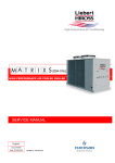
1
Himod
C Version
Service Manual
English
cod. 272631 - rev. 15.01.2003
Caution
We recommend that:
the manual is retained for the entire service life of the machine;
the user reads the manually carefully before carrying out any operations on the machine;
the control is used exclusively for the purpose for which it is intended; incorrect use of the control shall release the manufac
turer from any liability.
This manual has been prepared to enable the end-user to carry out only the operations that can be made with the panels closed.
Any operations that require the opening of doors or equipment panels must be carried out only by qualified personnel.
Each machine is equipped with an Electric Insulating device which allows the operator to work in conditions of safety. This de
vice must always be used to eliminate risks during maintenance (electric shocks, scalds, automatic restarting, moving parts and
remote control).
The panel key supplied with the unit must be kept by the person responsible for maintenance.
For identification of the unit (model and serial no.) in case of the necessity for assistance or spare parts, locate the identification
label on the outside of the unit.
Index
1 - Preliminary operations . . . . . . . . . . . . . . . . . . . . . . . . . . . . . . . . . . . . . . . . . . . . . . . . . . . . . . . . . . . . . . . 1
1.1 -
Inspection . . . . . . . . . . . . . . . . . . . . . . . . . . . . . . . . . . . . . . . . . . . . . . . . . . . . . . . . . . . . . . . . . . . . . . . . . . . 1
1.2 -
Handling . . . . . . . . . . . . . . . . . . . . . . . . . . . . . . . . . . . . . . . . . . . . . . . . . . . . . . . . . . . . . . . . . . . . . . . . . . . . 1
1.3 -
Operating limits . . . . . . . . . . . . . . . . . . . . . . . . . . . . . . . . . . . . . . . . . . . . . . . . . . . . . . . . . . . . . . . . . . . . . . 1
1.4 -
Identification . . . . . . . . . . . . . . . . . . . . . . . . . . . . . . . . . . . . . . . . . . . . . . . . . . . . . . . . . . . . . . . . . . . . . . . . 1
2 - Positioning . . . . . . . . . . . . . . . . . . . . . . . . . . . . . . . . . . . . . . . . . . . . . . . . . . . . . . . . . . . . . . . . . . . . . . . . . 2
2.1 -
Clearance areas and main dimensions . . . . . . . . . . . . . . . . . . . . . . . . . . . . . . . . . . . . . . . . . . . . . . . . . . . 2
2.2 -
Overall dimensions . . . . . . . . . . . . . . . . . . . . . . . . . . . . . . . . . . . . . . . . . . . . . . . . . . . . . . . . . . . . . . . . . . . 3
3 - Installation . . . . . . . . . . . . . . . . . . . . . . . . . . . . . . . . . . . . . . . . . . . . . . . . . . . . . . . . . . . . . . . . . . . . . . . . . 4
3.1 -
Air inlet and outlet . . . . . . . . . . . . . . . . . . . . . . . . . . . . . . . . . . . . . . . . . . . . . . . . . . . . . . . . . . . . . . . . . . . 4
3.2 -
Hole in raised floor . . . . . . . . . . . . . . . . . . . . . . . . . . . . . . . . . . . . . . . . . . . . . . . . . . . . . . . . . . . . . . . . . . 4
3.3 -
Extension hood . . . . . . . . . . . . . . . . . . . . . . . . . . . . . . . . . . . . . . . . . . . . . . . . . . . . . . . . . . . . . . . . . . . . . . 5
3.4 -
Extension hood with sound reduction cartridges (Over unit) . . . . . . . . . . . . . . . . . . . . . . . . . . . . . . . . 5
3.5 -
Horizontal discharge hood (Over unit) . . . . . . . . . . . . . . . . . . . . . . . . . . . . . . . . . . . . . . . . . . . . . . . . . . . 5
3.6 -
Base module . . . . . . . . . . . . . . . . . . . . . . . . . . . . . . . . . . . . . . . . . . . . . . . . . . . . . . . . . . . . . . . . . . . . . . . . . 6
3.7 -
Base frame . . . . . . . . . . . . . . . . . . . . . . . . . . . . . . . . . . . . . . . . . . . . . . . . . . . . . . . . . . . . . . . . . . . . . . . . . . 6
3.8 -
High efficiency filters . . . . . . . . . . . . . . . . . . . . . . . . . . . . . . . . . . . . . . . . . . . . . . . . . . . . . . . . . . . . . . . . . 6
3.9 -
New Air module . . . . . . . . . . . . . . . . . . . . . . . . . . . . . . . . . . . . . . . . . . . . . . . . . . . . . . . . . . . . . . . . . . . . . 7
4 - Water connections . . . . . . . . . . . . . . . . . . . . . . . . . . . . . . . . . . . . . . . . . . . . . . . . . . . . . . . . . . . . . . . . . . . 8
4.1 -
General warnings . . . . . . . . . . . . . . . . . . . . . . . . . . . . . . . . . . . . . . . . . . . . . . . . . . . . . . . . . . . . . . . . . . . . . 8
4.2 -
Auxiliary water connections . . . . . . . . . . . . . . . . . . . . . . . . . . . . . . . . . . . . . . . . . . . . . . . . . . . . . . . . . . . . 8
4.3 -
Chilled water connections
4.4 -
Adding ethylene glycol . . . . . . . . . . . . . . . . . . . . . . . . . . . . . . . . . . . . . . . . . . . . . . . . . . . . . . . . . . . . . . . . 8
............................................................ 8
5 - Electrical connections . . . . . . . . . . . . . . . . . . . . . . . . . . . . . . . . . . . . . . . . . . . . . . . . . . . . . . . . . . . . . . . 16
5.1 -
Electrical connections . . . . . . . . . . . . . . . . . . . . . . . . . . . . . . . . . . . . . . . . . . . . . . . . . . . . . . . . . . . . . . . . 16
5.2 -
Fan connections . . . . . . . . . . . . . . . . . . . . . . . . . . . . . . . . . . . . . . . . . . . . . . . . . . . . . . . . . . . . . . . . . . . . . 19
5.3 -
Aeraulic features . . . . . . . . . . . . . . . . . . . . . . . . . . . . . . . . . . . . . . . . . . . . . . . . . . . . . . . . . . . . . . . . . . . . 23
6 - Start-up . . . . . . . . . . . . . . . . . . . . . . . . . . . . . . . . . . . . . . . . . . . . . . . . . . . . . . . . . . . . . . . . . . . . . . . . . . 24
6.1 -
First start-up (or after long standstill) . . . . . . . . . . . . . . . . . . . . . . . . . . . . . . . . . . . . . . . . . . . . . . . . . 24
English
6.2 6.3 -
Starting and stopping . . . . . . . . . . . . . . . . . . . . . . . . . . . . . . . . . . . . . . . . . . . . . . . . . . . . . . . . . . . . . . . . 24
Automatic restart . . . . . . . . . . . . . . . . . . . . . . . . . . . . . . . . . . . . . . . . . . . . . . . . . . . . . . . . . . . . . . . . . . . 24
7 - Operation . . . . . . . . . . . . . . . . . . . . . . . . . . . . . . . . . . . . . . . . . . . . . . . . . . . . . . . . . . . . . . . . . . . . . . . . . 25
7.1 -
Chilled water valve . . . . . . . . . . . . . . . . . . . . . . . . . . . . . . . . . . . . . . . . . . . . . . . . . . . . . . . . . . . . . . . . . . 25
8 - Calibrations . . . . . . . . . . . . . . . . . . . . . . . . . . . . . . . . . . . . . . . . . . . . . . . . . . . . . . . . . . . . . . . . . . . . . . . 26
9 - Maintenance / Spare Parts . . . . . . . . . . . . . . . . . . . . . . . . . . . . . . . . . . . . . . . . . . . . . . . . . . . . . . . . . . . 26
9.1 9.2 App. A -
Spare parts . . . . . . . . . . . . . . . . . . . . . . . . . . . . . . . . . . . . . . . . . . . . . . . . . . . . . . . . . . . . . . . . . . . . . . . . . 26
Dismantling the unit . . . . . . . . . . . . . . . . . . . . . . . . . . . . . . . . . . . . . . . . . . . . . . . . . . . . . . . . . . . . . . . . . 26
HUMIDAIR humidifier . . . . . . . . . . . . . . . . . . . . . . . . . . . . . . . . . . . . . . . . . . . . . . . . . . . . . . . . . .
App. A.1 Preface . . . . . . . . . . . . . . . . . . . . . . . . . . . . . . . . . . . . . . . . . . . . . . . . . . . . . . . . . . .
App. A.2 Installation . . . . . . . . . . . . . . . . . . . . . . . . . . . . . . . . . . . . . . . . . . . . . . . . . . . . . . .
App. A.3 Humidair components . . . . . . . . . . . . . . . . . . . . . . . . . . . . . . . . . . . . . . . . . . . . . .
App. A.4 Start-up and operation . . . . . . . . . . . . . . . . . . . . . . . . . . . . . . . . . . . . . . . . . . . .
App. A.4.1 App. A.4.2 -
Start-up . . . . . . . . . . . . . . . . . . . . . . . . . . . . . . . . . . . . . . . . . . . . . . . . . . A - 3
Operation . . . . . . . . . . . . . . . . . . . . . . . . . . . . . . . . . . . . . . . . . . . . . . . . . A - 3
App. A.5 -
Maintenance . . . . . . . . . . . . . . . . . . . . . . . . . . . . . . . . . . . . . . . . . . . . . . . . . . . . . . A - 3
App. A.6 -
Spare part list . . . . . . . . . . . . . . . . . . . . . . . . . . . . . . . . . . . . . . . . . . . . . . . . . . . . . A - 4
App. A.5.1 App. A.5.2 App. A.5.3 -
Removing the steam cylinder . . . . . . . . . . . . . . . . . . . . . . . . . . . . . . . . . A - 3
Replacing the steam cylinder . . . . . . . . . . . . . . . . . . . . . . . . . . . . . . . . . . A - 3
Annual maintenance . . . . . . . . . . . . . . . . . . . . . . . . . . . . . . . . . . . . . . . . A - 3
The Service Manual HIMOD can also be surfed on the Web at the address: www.HIROSS.IT/pde/TDS/Himod
This document is password-protected. Ask for the password to your Dealer/Area Manager.
English
A-1
A-1
A-1
A-2
A-3
1 - Preliminary operations
1.1 - Inspection
On receiving the equipment immediately check its
condition; report any damage to the transport compa
ny at once.
1.2 - Handling
Always keep the unit vertically upright and do not
leave it out in the open.
If possible transport the unit using a fork lift truck;
otherwise use a crane with belts or cables, avoiding
pressing on the top edges of the packing.
1.3 - Operating limits
The units are designed to operate within working
ranges (see Tab. 1).
These limits are referred to new machines or to those
that have been correctly installed and serviced.
The warranty clauses are no longer valid for any pos
sible damage or malfunction that may occur during or
due to operation outside the application values.
1.4 - Identification
The air conditioner can be identified according to the
following nomenclature:
27 U C
Model
Air distribution:
U = Under (downflow)
O = Over (upflow)
Cooling circuit:
A = air-cooled
W = water-cooled
C = chilled water
F = Freecooler
D = Dualfluid (air-cooled)
H = Dualfluid (water-cooled)
To view the Service Manual HIMOD version
A/W/F/D/H, refer to the Manual code 272157
Tab. 1 - Operating limits
Room conditions
from:
18°C, 45% R.H.
to:
27°C, 55% R.H
standard
Voltage tolerances
optional
400V 10%/3/50
208230V 10%/3/60
380V 10%/3/60
460V 10%/3/60
Hot water heating coil
Chilled water coil
inlet water
temperature
water pressure
inlet water
temperature
max. 8.5 bar
water pressure
max. 16 bar
from:
Storage conditions
to:
UNDER
English
max. 85°C
min. 5°C
- 20°C
50°C
OVER
HIMOD-C
1
2 - Positioning
2.1 -
Clearance areas and main dimensions
MODEL
27-45 O/UC
55-65-80-85 O/UC
90-10 UC
12-14 UC
1000
1740
800
890
50
1950
1750
1740
800
890
50
1950
2050
1740
800
890
50
1950
2550
1740
800
890
50
1950
A [mm]
B [mm]
C [mm]
D [mm]
E [mm]
F [mm]
2
MODEL
WEIGHT (kg) - standard unit
27 UC
45 UC
55 UC
65 UC
80 UC
85 UC
90 UC
10 UC
12 UC
14 UC
27 OC
45 OC
55 OC
65 OC
80 OC
85 OC
290
340
495
555
590
610
660
670
830
840
290
340
495
555
590
610
HIMOD-C
English
2.2 -
Overall dimensions
Under Version
27-45 UC
55-65-80-85 UC
1750
40
1950
1000
5
990
5
5
90-10 UC
1740
5
50
5
885
12-14 UC
2550
40
1950
2050
5
2040
5
5
2540
5
50
5
885
Over Version
27-45 OC
55-65-80-85 OC
1750
40
1950
1000
5
English
990
5
5
1740
HIMOD-C
5
50
890
3
3 - Installation
ATTENTION: The conditioner must never be installed out of doors.
3.1 -
Air inlet and outlet
27-45 C - under
55-65-80-85 C - under
A
B
C
D
910
1580
778
778
40
80
52
52
E
F
910 804
55-65-80-85 C - under 1660 804
27-45 C - under
90-10 C - under
12-14 C - under
12-14 C - under
H
L
43
43
43
43
45
45
A
B
C
D
1960
2460
297
297
40
40
483
483
E
90-10 C - under
G
F
1960 799
2460 799
G
H
L
43
43
46
46
45
45
Look-through rear view
ATTENTION: About the upflow (over) units, the extraordinary removal of the fan (560 mm blade diameter) is per
mitted only from the top of the unit.
Please keep it on mind during the possible ducting design and manufacturing.
3.2 -
4
Hole in raised floor
A [mm]
B [mm]
C [mm]
27-45 C
without base frame
with base frame
900
1000
810
885
93
48
55-65-80-85 C
without base frame
with base frame
1650
1750
810
885
93
48
A [mm]
B [mm]
C [mm]
90-10 UC
without base frame
with base frame
1970
2050
810
885
93
48
12-14 UC
without base frame
with base frame
2470
2550
810
885
93
48
HIMOD-C
English
Extension hood
false ceiling
3.3 -
A
1000
1750
2050
2550
27-45 C
55-65-80-85 C
90-10 UC
12-14 UC
3.4 -
Extension hood with sound reduction car
tridges (Over unit)
3.5 -
B
890
890
890
890
C
500 / 1200
500 / 1200
500 / 1200
500 / 1200
Horizontal discharge hood (Over unit)
front
27-45 C
55-65-80-85 C
English
HIMOD-C
D
30
30
30
30
back
A
1000
1750
B
890
890
C
600/900
600/900
5
3.6 - Base module
If there is no raised floor below the unit it must be
placed on a base module to allow access to the external
connections.
The conditioner is connected to the base module by 4
screws.
27-45 C
55-65-80-85 C
90-10 UC
12-14 UC
3.8 -
6
A
B
C
990
1740
2040
2540
885
885
885
885
200
200
200
200
3.7 -
Base frame
High efficiency filters
HIMOD-C
English
3.9 -
New Air module
UNDER
OVER
(C version)
(C version)
UNDER
UNDER
(Mod. 90–10 – C version)
(Mod. 12–14 – C version)
English
HIMOD-C
7
4 - Water connections
4.1 - General warnings
ENSURE THAT THE TUBING DOES NOT OB
STRUCT THE AIR FLOW(Under only).
IF THE TUBING IS TO RUN OUTDOORS, ADD
ETHYLENE GLYCOL TO THE CIRCUIT AS DE
SCRIBED IN PARA. 4.4.
4.2 - Auxiliary water connections
- Condensate drain (Fig. 1):
Use galvanized steel, PVC or flexible polythene
tubing.
Allow a 2% gradient towards the drain outlet.
There must be a drain trap (1) placed at least 30
mm below the drain tray (2).
Fill the drain trap with water (3).
Place shut-off ball valves (3) at the conditioner in
let and outlet to allow easy maintenance.
It is useful to install a thermometer (4) and a ma
nometer (5) at the conditioner inlet and outlet.
Install a water drain tap (6) at the lowest point in
the circuit.
Place a control valve (7) in the outlet water tubing.
Fill the circuit with water/glycol (see below), up to
a maximum pressure of 7 bar.
Fig. 2 - Chilled water circuit
Air
conditioner
Fig. 1 - Condensate drain
2
4
5
2
1
min.
30 mm
3
1
4.4 -
3
Adding ethylene glycol
Tab. 2 - Ethylene glycol to be added to water
BRACKET
to be
connected
by user
freezing temperature
(C)
0
-5
-11
-18
-27
-39
ethylene glycol to add to
water (% in weight of
total mixture)
0
10
20
30
40
50
N.B. Values are for Shell antifreeze 402. For different brands check manufacturer's data.
- Humidifier (optional): See App. A.
- Hot water (optional):
Use copper or steel (Mannesmann) tubing.
Insulate both tubes using Armaflex insulation.
4.3 - Chilled water connections
Use copper or steel (Mannesmann) tubing.
Place the tubing on supporting saddles (1).
Insulate both tubes using Armaflex insulation (2).
8
7
6
NOTES:
To avoid stratification run the circulation pump for
at least 30 min. after adding any glycol.
After adding water to the water circuit, disconnect
the unit from the sanitary water piping system; in
this way the water mixed with glycol won't return
into the same piping system.
After any topping-up of water check the glycol
concentration and add any glycol if necessary.
The hydraulic features of the system vary by adding
glycol. Therefore check the head and the flow rate
of the pump to be used.
HIMOD-C
English
Himod C
under
Fig. 3 - Chilled water connections
140
27-45
125
120
Right side view
(DX)
150
Frontal view
A
B
A
B
140
55-65-80-85
Right side view
(DX)
125
120
150
Frontal view
A
B
A B
POS
POS.
CONNECTION
DIMENSION
27C
45-55C
65-80-85C
A
Chilled water inlet
1 " female
1 ¼" female
1 ½" female
B
Chilled water outlet
1 " female
1 ¼" female
1 ½" female
English
HIMOD-C
9
Himod C
under
Fig. 4 - Chilled water connections
200
90 - 10
95
Right side view
(DX)
100
180
Frontal view
A
B
A B
200
12-14
95
Right side view
(DX)
110
Frontal view
185
A
B
POS
POS.
10
A B
DIMENSION
CONNECTION
90-10 C
12-14 C
A
Chilled water inlet
2 " male
2 ½" male
B
Chilled water outlet
2 " male
2 ½" male
HIMOD-C
English
Himod C
over
Fig. 5 - Chilled water connections
160 / 200
27-45
220
150
Left side view
(SX)
300
Frontal view
A
B
A B
90 (80-85 C)
170 (55-65 C)
55-65-80-85
220
150
Left side view
(SX)
300
Frontal view
A
B
A B
POS
POS.
CONNECTION
DIMENSION
27C
45-55C
65-80-85C
A
Chilled water inlet
1 " female
1 ¼" female
1 ½" female
B
Chilled water outlet
1 " female
1 ¼" female
1 ½" female
English
HIMOD-C
11
Himod C
under/over
Fig. 6 - Auxiliary water connections
Under single / double
Frontal view
155
80
145
Left side view 105
(SX)
90
215
D
A
E
E
D
E
B
D
D
E
C
80-85
27-45-55-65
80-85
27-45-55-65
80-85
27-45-55-65
27-45
105
Frontal view
Over single / double
170
105
Frontal view
D
A
E
B
27-45
55-65-80-85
55-65-80-85
170
Left side view
(SX)
D
D
E
E
C
POS.
A
B
C
D/E (small)
D/E (big)
12
CONNECTION
HUMIDAIR water supply (optional)
HUMIDAIR water drain (optional)
Condensate drain
Hot water inlet/outlet (optional)
Hot water inlet/outlet (optional)
HIMOD-C
590
A
B
C
DIMENSION
½" G male
22 mm female
20 mm female
18 x 1 mm
22 x 1 mm
English
Himod C
under
Fig. 7 - Auxiliary water connections
90-10
105
90
Frontal view
135
490
B
85
Left side view
(SX)
67
C
D
E
A
E
B
D
A
C
12-14
105
90
Frontal view
135
480
B
85
C
Left side view
(SX)
67
D
E
A
E
D
B
A
C
POS.
A
B
C
D/E
English
CONNECTION
HUMIDAIR water supply (optional)
HUMIDAIR water drain (optional)
Condensate drain
Hot water inlet/outlet (optional)
HIMOD-C
DIMENSION
½" G male
22 mm female
20 mm female
22 x 1 mm
13
Himod C
27-55-65
Fig. 8 - Water circuit
1
5
2
4
3
COOLING WATER INLET
COOLING WATER OUTLET
HOT WATER OUTLET
HOT WATER INLET
POS.
14
DESCRIPTION
1
Chilled water coil
2
Reheating coil (optional)
3
ON-OFF 3-way valve (optional)
4
Chilled water 3-way valve
5
Air purge valve
HIMOD-C
English
Himod C
45-80-85-90-10-12-14
Fig. 9 - Water circuit
1
1
5
2
4
3
COOLING WATER INLET
COOLING WATER OUTLET
HOT WATER OUTLET
HOT WATER INLET
POS.
English
DESCRIPTION
1
Chilled water coil
2
Reheating coil (optional)
3
ON-OFF 3-way valve (optional)
4
Chilled water 3-way valve
5
Air purge valve
HIMOD-C
15
5 - Electrical connections
5.1 -
Electrical connections
1) Before proceeding with the electrical connections,
ensure that:
all electrical components are undamaged;
all terminal screws are tight;
the supply voltage and frequency are as indicated
on the unit.
2) Power supply cable connections (see Fig. 10):
Connect the cable to the Line inlet terminal
board.
Use the cable size defined according to the flow
(see Fig. 11), the supply voltage and the installa
tion type.
Protect the supply using a back-up fuse.
Do not fit the supply cable in the raceways inside
the machine electric board.
Use multipolar cables with sheath (CEI20-22)
only.
3) Wiring connections:
Connections for remote on-off and hot water
consent must be done by the installer.
The General Alarm terminals allow remote
alarm signalling.
4) In case of short circuit, check the sticking of the in
volved remote control switch and possibly replace
it.
Fig. 10 - Supply cable passage
Under unit
Under unit
(Mod. 90-10 C version)
16
Over unit
Under unit
(Mod. 12-14 C version)
HIMOD-C
English
Fig. 11 - Electrical connections
AUXILIARY TERMINAL BOARD
clogged
filter (CF)
fans
operating
remote on-off
NC* C* NO*
1
1
1
1
02 G
G
G0 G0 G0
24
24
24
19
50 020 30 33
55
055 102 70
smokestat
firestat (AAP)
71
72
73 400 401 402
GENERAL ALARM
user alarm
(or AAP)
401 - 402: alarm signal
401 - 400: alarm off
water
leakage
(LWD)
* unit under power
Supply cable inlet
Tab. 3 - Electrical data
CONFIGURATION
50 Hz
LRA
(A)
RESIDUAL-CURRENT CIRCUIT BREAKERS
In = 0.3A (400V)
4,8
16,0
10A
9,7
32,0
16A
17,3
35,6
16A
17,3
53,4
25A
13,3
16,0
16A
26,7
32,0
32A
34,3
35,6
50A
34,3
53,4
50A
22,3
22,3
32A
35,7
35,7
50A
47,3
47,3
63A
47,3
47,3
63A
FLA
(A)
MODELS
3ph / 400V
(F): Cooling
Fan(s)
()
(F+C): Cooling + Electrical heating
Fan(s)
( ) + heatingg
(F+C+H):
(F
C H) C
Cooling
li + El
Electrical
t i l
heating + Humidity
Fan(s) + heating, + humidification
English
27 45 C
55 65 80 85 C
90 - 10 U C
12 - 14 U C
27 45 C
55 65 80 85 C
90 - 10 U C
12 - 14 U C
27 45 C
55 65 80 85 C
90 - 10 U C
12 - 14 U C
HIMOD-C
17
60 Hz
FLA
(A)
CONFIGURATION
MODELS
(F): Cooling
Fan(s)
(F+C): Cooling + Electrical heating
Fan(s) + heating
27 45 C
55 65 80 85 C
27 45 C
55 65 80 85 C
(F+C+H): Cooling + Electrical
heating + Humidity
Fan(s) + heating + humidification
LRA
(A)
RESIDUAL-CURRENT CIRCUIT BREAKERS
In = 0.3A (400V)
3ph / 208-230V
8,9
35,4
16A
17,8
70,8
25A
24,3
35,4
32A
48,6
70,8
50A
27 45 C
33,3
33,3
63A
55 65 80 85 C
57,6
57,6
80A
4,9
20,4
10A
9,7
40,8
16A
13,8
20,4
16A
27,5
40,8
32A
27 45 C
22,8
22,8
40A
55 65 80 85 C
36,5
36,5
50A
4,0
16,0
10A
8,0
32,0
10A
11,4
16,0
16A
22,7
32,0
25A
27 45 C
20,4
20,4
32A
55 65 80 85 C
31,7
31,7
40A
3ph / 380V
(F): Cooling
Fan(s)
(F+C): Cooling + Electrical heating
Fan(s) + heating
(F+C+H): Cooling + Electrical
heating + Humidity
Fan(s) + heating + humidification
27 45 C
55 65 80 85 C
27 45 C
55 65 80 85 C
3ph / 460V
(F): Cooling
Fan(s)
(F+C): Cooling + Electrical heating
Fan(s) + heating
(F+C+H): Cooling + Electrical
heating +Humidity
Fan(s) + heating + humidification
27 45 C
55 65 80 85 C
27 45 C
55 65 80 85 C
NOTES:
18
The cables have to be sized in compliance with local standards and according to the type and characteristics (e.g. Amperes) of installation.
The specific power the user-installed switch allows must be lower than 300,000 A2 x s.
Prescriptions on the differential relay required to the user:
for special places (healthcare facilities, etc...) comply with the local regulations;
For ordinary places, a low sensitivity is suggested (300 mA) coordinated with the value of the ground heater (IEC 364): Ra v 50/Ia (Art.
413.1.4.1, CEI 64-8);
In case of frequent over-voltages with mains impulse, it is advisable to install a selective differential and to evaluate the need for adopting
other devices.
(Models 90-10-12-14 U C only) The value of current (Full Load Ampere) is calculated considering electric heaters running at a capacity
of 17,55 kW, configuration F+C and F+C+H.
HIMOD-C
English
5.2 - Fan connections
The fan is electrically feeded by an autotransformer
that is connected by the constructor in order to obtain
the nominal air flow and the Available External Static
Pressure (AESP).
To change the factory connection proceed as follow:
- identify the unit's graph;
- choose the curve's point where both the air flow
and the static pressure are the most suitable for the
installation;
- check the factory fan blocks connection ( or )
and correct if necessary (see Fig. 12);
- find the output connectors and the bridges corre
sponding to the graph values (see para. 5.3;
- connect the bridges and the output connectors;
- connect the 400V supply cables to the C" termi
nals.
After a wiring modification, execute a
loadless test on the autotransformer.
Check the voltage of each wire, in order
not to damage the transformer (always
refer to the output voltage column va
lues).
N.B. A FAN SPEED VARIATION CHANGES THE WOR
KING CONDITION OF THE UNIT.
Fig. 12 - Example of electrical connection to the autotransformer
AUTOTRANSFORMER
E
E
In the example picture, the power supply
voltage required is 260 V, at 50 Hz.. The fan
blocks are connected.
E
260V
autotransformer
output
FAN MOTOR
Reference colors:
u1 : brown
w1 : black
v2 : grey
klixon: white
English
v1 : light blue
u2 : red
w2 : orange
PE : yellow/green
HIMOD-C
19
Tab. 4 - Autotransformer output connections
50 Hz
autotrasformer outlet voltage
output STD
graph value
(1)
output
connectors
bridge
fan connection
fan connection
185
E
A↔H
185
-
200
E
A↔G
200
-
215
E
A↔F
215
-
230
A
-
230
-
245
F
A↔E
245
-
260
G
A↔E
260
-
275
H
A↔E
275
160 (156)
280
E
B↔G
280
160 (162)
295
E
B↔F
295
170 (167)
310
B
-
310
180 (179)
325
F
B↔E
325
180 (185)
340
G
B↔E
340
200 (196)
355
H
B↔E
355
200 (202)
370
E
C↔G
370
210 (214)
385
E
C↔F
385
220 (219)
400
C
-
400
230 (231)
60 Hz
autotrasformer outlet voltage
(1)
20
output STD
graph value
(1)
output
connectors
bridge
fan connection
fan connection
190
E
B↔G
190
-
208
A
-
208
-
210
E
B↔F
210
-
230
B
-
230
-
250
F
B↔E
250
-
270
G
B↔E
270
160 (156)
290
H
B↔E
290
170 (167)
320
E
C↔H
320
180 (179)
340
E
C↔G
340
200 (196)
360
E
C↔F
360
210 (214)
380
C
-
380
220 (219)
400
F
C↔E
400
230 (231)
420
G
C↔E
420
-
440
H
C↔E
440
-
460
D
-
460
-
connection: fan inlet voltage = autotrasformer outlet voltage
connection: fan inlet voltage = autotrasformer outlet voltage multiplied by 0.577
HIMOD-C
English
Tab. 5 - Standard fan connections for HIMOD with autotransformer
50 Hz
Standard
Model
autotrasformer outlet voltage
(1)
connections
output connectors
bridge
25/27U C
215
E
A↔F
35/45U C
215
E
A↔F
50/55U C
230
A
-
60/65U C
230
A
-
70/80U C
230
A
-
75/85U C
230
A
-
90U C
260
G
A↔E
10U C
280
E
B↔G
12U C
260
G
A↔E
14U C
325
F
B↔E
25/27O C
230
A
-
35/45O C
230
A
-
50/55O C
230
A
-
60/65O C
230
A
-
70/80O C
230
A
-
75/85O C
230
A
-
60 Hz
Standard
(1)
English
Model
autotrasformer outlet voltage
(1)
connections
output connectors
bridge
27U C
250
F
B↔E
45U C
250
F
B↔E
55U C
260
G
A↔E
65U C
260
G
A↔E
80U C
280
E
B↔G
85U C
280
E
B↔G
27O C
270
G
B↔E
45O C
270
G
B↔E
55O C
260
G
A↔E
65O C
260
G
A↔E
80O C
280
E
B↔G
85O C
280
E
B↔G
connection: fan inlet voltage = autotrasformer outlet voltage
connection: fan inlet voltage = autotrasformer outlet voltage multiplied by 0.577
HIMOD-C
21
Tab. 6 - Electrical data
50 Hz
FAN
(3ph - 160 400V)
component
Model
OA
(A)
FLA
(A)
LRA
(A)
absorbed power
(kW)
27U C
4.3
4.4
16
1.4
45U C
4.3
4.4
16
1.4
55U C
2 x 4.3
2 x 4.4
2 x 16
2 x 1.5
65U C
2 x 4.3
2 x 4.4
2 x 16
2 x 1.5
80U C
2 x 4.3
2 x 4.4
2 x 16
2 x 1.5
85U C
2 x 4.3
2 x 4.4
2 x 16
2 x 1.5
90U C
2 x 5.8
2 x 6.0
2 x 17.8
2 x 2.4
10U C
2 x 5.9
2 x 6.0
2 x 17.8
2 x 2.6
12U C
3 x 5.9
3 x 6.0
3 x 17.8
3 x 2.5
14U C
3 x 5.9
3 x 6.0
3 x 17.8
3 x 3.1
27O C
4.3
4.4
16
1.5
45O C
4.3
4.4
16
1.5
55O C
2 x 4.3
2 x 4.4
2 x 16
2 x 1.5
65O C
2 x 4.3
2 x 4.4
2 x 16
2 x 1.5
80O C
2 x 4.4
2 x 4.4
2 x 16
2 x 1.6
85O C
2 x 4.4
2 x 4.4
2 x 16
2 x 1.6
60 Hz
FAN
(3ph - 160 460V)
component
Model
OA
(A)
FLA
(A)
LRA
(A)
absorbed power
(kW)
27U C
3.4
3.5
16
1.1
45U C
3.4
3.5
16
1.2
55U C
2 x 3.3
2 x 3.5
2 x 16
2 x 1.2
65U C
2 x 3.4
2 x 3.5
2 x 16
2 x 1.2
80U C
2 x 3.2
2 x 3.5
2 x 16
2 x 1.2
85U C
2 x 3.3
2 x 3.5
2 x 16
2 x 1.2
27O C
3.3
3.5
16
1.2
45O C
3.3
3.5
16
1.2
55O C
2 x 3.3
2 x 3.5
2 x 16
2 x 1.2
65O C
2 x 3.3
2 x 3.5
2 x 16
2 x 1.2
80O C
2 x 3.3
2 x 3.5
2 x 16
2 x 1.3
85O C
2 x 3.3
2 x 3.5
2 x 16
2 x 1.3
1.
The fan OA" value and the absorbed power are refered to standard air flow; Under unit with underflow air discharge and 20 Pa available exter
nal static pressure; Over unit with ducted air discharge and 50 Pa available external static pressure.
NOTE: the indicated fan currents are measured on their terminal boards; to calculate the current absorption of the fans to the machine supply
terminals multiply the indicated values by the selected transforming ratio (see Tab. 4).
22
HIMOD-C
English
Tab. 7 - Optional electrical data
50 Hz
Component
Model
ELECTRICAL HEATING
FLA (A)
rated power [kW]
HUMIDIFIER
FLA (A)
rated power [kW]
90
9.0
58
5.8
13 0
13.0
90
9.0
(400V / 3Ph / 50Hz)
27-45 U/O C
8.5
5.85
55-65-80-85 U/O C
17.0
11.70
17.0
11.70
25.4
17.55
90-10-12-14 U C
60 Hz
Component
Model
ELECTRICAL HEATING
FLA (A)
rated power [kW]
HUMIDIFIER
FLA (A)
rated power [kW]
15 0
15.0
58
5.8
90
9.0
58
5.8
80
8.0
58
5.8
(208-230V / 3Ph / 60Hz)
27-45 U/O C
15.4
5.85
55-65-80-85 U/O C
30.8
11.70
(380V / 3Ph / 60Hz)
27-45 U/O C
8.9
5.85
55-65-80-85 U/O C
17.8
11.70
(460V / 3Ph / 60Hz)
27-45 U/O C
7.4
5.85
55-65-80-85 U/O C
14.7
11.70
5.3 - Aeraulic features
The aeraulic features, namely the values of the useful
static pressure while the voltage changes (graphs), can
be surfed on the Web at the following address:
www.HIROSS.IT/pde/TDS/Aeraulic_features
This document is password-protected. Ask for the password
to your Dealer/Area Manager.
English
HIMOD-C
23
6 - Start-up
6.1 -
First start-up (or after long stand
still)
Start the air conditioner as follows:
1) Open all valves in the water circuit according to the
instruction label attached to the valve.
2) Check that there are no water leakages.
3) Bleed all air out of the chilled water circuit using
the bleed valve on the chilled water coil.
4) Close all MCBs on the electrical panel.
5) Check the supply voltage on all phases.
6) Start the unit by pressing ON OFF (see Fig. 13).
7) Check the electrical absorption of all components
(see Chap. 5).
8) Ensure that the fans rotate in the correct direction
(see arrow on fan).
9) Ensure that all control system settings are correct
and that there are no alarms (see Control manual).
10)Verify the water flow.
11)Verify the Fresh Air Intake operation (if fitted).
12)Once the system is operating under load, check the
various components, as follows:
Verify that the fans are operating properly.
Ensure that the temperature and relative hu
midity are being controlled, and that the humid
ifier (optional) and heating steps (optional) op
erate when required.
Ensure that chilled water valve operates when
required.
24
6.2 - Starting and stopping
Turn on the unit operating on the ON/OFF switch pla
ced on the left case of the unit (Fig. 13). If the ON/OFF
remote device is not installed, the green LED on the
Microface case will light up together with the LED pla
ced below the ON/OFF switch. The fan starts imme
diately (the fan always works when the unit is ON); af
ter 2 minutes the regulation is activated, so the cooling
(compressor), heating (electric heaters), humidifying
and dehumidifying devices can start.
Adjust the set-point as indicated in Control ma
nual.
Stop the unit putting the ON/OFF switch in OFF.
The main switch QS should only be switched off if
the unit is stopped for a long period of time.
6.3 - Automatic restart
If desired, the unit will automatically restart on the re
turn of power after a supply interruption (see Control
manual).
Fig. 13 - On-Off switch
HIMOD-C
English
7 - Operation
Unit operation is completely automatic. The below se
quence explains how the unit operates :
The air, sucked in by the fan(s), enters the unit.
The air is immediately filtered.
The TEMPERATURE sensor or HUMITEMP (tem
perature + rel. humidity) sensor (check type
installed), verifies the state of the inlet air, and relays
this information to the control system.
The control system compares the relayed informa
tion to the set point and proportional band values
programmed into its memory: it then commands the
air conditioner to treat the air as follows (see also
Control manual):
COOLING
Chilled water flows through the chilled water
coil, thus cooling the air passing over it. The
chilled water flow is controlled by a timed mod
ulating (3-way) valve, which regulates the flow
rate in order to obtain the exact amount of cool
ing required.
HEATING
This can take one of two forms:
- electrical heating (optional): the heating ele
ments heat the air passing over them. There are
3 heating steps.
- hot water heating (optional): if hot water is
available, this flows through the hot water coil,
thus heating the air passing over it. The hot wa
ter flow is controlled by an on-off (3-way)
valve.
DEHUMIDIFICATION - optional
Maximum chilled water flow is requested
through the coil, whose temperature drops be
low the dew point of the air, thus dehumidifying
it.
If necessary, heating is used to reheat the air.
N.B.: If, during dehumidification, the ambient
temperature drops below a specified level, de
humidification will be stopped if necessary (see
LOW LIMIT intervention in Control manual).
HUMIDIFICATION - optional
The humidifier creates steam, which is distrib
uted into the air stream via the steam distribu
tion pipe (see also App. A).
Filtered new air is injected into the air stream via
the Fresh Air Intake.
The treated air passes through the fans, which op
erate continuously, and is then dispersed out of the
unit.
Under unit only: the air passes from the underfloor
void into the room via air distribution outlets.
N.B.: Manual control can be performed using the control
system (see Control manual).
7.1 - Chilled water valve
The 3-way valve controls the chilled water flow. It op
erates as follows (Fig. 14):
When the valve is fully open (i.e. max. chilled water
flow) the actuator slot is set to '1'.
When the valve is closed (i.e. no chilled water flow)
the actuator slot is set to '0'.
The valve running time is set to the value specified in
the Control Manual.
Note 1: In the unlikely event of control system failure,
the valve can be manually controlled by means of a 3
mm allen key placed into the actuator slot.
NEVER PERFORM THIS OPERATION USING A
SCREWDRIVER.
Note 2: For models 90-10-12-14 UC the chilled wa
ter valve is not foreseen for the manual operation.
When actuator stem is completely down the valve is
closed (by-pass 100%), when actuator stem is com
pletely up the valve is open (by-pass 0%) and all water
flows into the coil.
Fig. 14 - Position of the chilled water valve actuator
3 mm
Manual adjustment with 3 mm allen key
A
B
3
m
m
3 mm
B
English
A
Position indicator in
Position 0 = CLOSED
Valve Closed
(by-pass open)
HIMOD-C
Position indicator in
Position 1 = OPEN
Valve fully Open
(by-pass closed)
25
8 - Calibrations
The air conditioner has already been factory-te
sted and calibrated as shown below.
COMPONENT
Fan differential
pressure switch
Clogged filter
differential pressure switch
(CF)
SETTING
NOTES
0.8 mbar
calibrate
Filters G4 = 2 mbar
9 - Maintenance / Spare Parts
AS THE HIROMATIC/MICROFACE FEATURES
AUTOMATIC RESTART (AFTER A SUPPLY IN
TERRUPTION) IT IS ADVISED TO EITHER DI
SABILITATE AUTORESTART OR TO OPEN
SWITCH QS WHEN PERFORMING ANY MAIN
TENANCE.
On a daily basis check the HIROMATIC/MICRO
FACE readings for temperature and, if shown, rel.
humidity.
The Maintenance Programme below should be car
ried out by a qualified technician, preferably wor
king under a maintenance contract.
Maintenance schedule - Monthly check
Check that the fan motor rotates freely without any abnormal noise, and en
sure that the bearings are not running hot.
FANS
Also check the current absorption.
Verify the state of the filters; if necessary clean or replace them.
AIR FILTERS
In very dusty ambients perform this check more frequently.
NEW AIR FILTER
Verify the state of the filter; if necessary clean or replace it.
(if fitted)
CONTROL SYSTEM
Verify the operation of LEDs, display and alarms.
HUMIDIFIER
See App. A.
(if fitted)
Check the electrical supply on all phases.
ELECTRICAL
CIRCUIT
Ensure that all electrical connections are tight.
Ensure that there are no water leaks.
Bleed any air out of the chilled water circuit using the bleed valve situa
ted on the top right of the chilled water coil.
CHILLED WATER
CIRCUIT
Verify the correct chilled water flow.
Check the inlet - outlet fluid temperature and pressure using the ther
mometers and manometers, if fitted.
9.1 - Spare parts
It is recommended the use of original spare parts.
When placing an order refer to Component List" en
closed with the machine and quote the unit model no.
and serial no.
The working life of some of the main components,
such as the fan and the compressor, depends on the
maintenance that they receive.
If the unit has to be dismantled, this operation must be
done by skilled refrigeration technicians.
9.2 - Dismantling the unit
The machine has been designed and built to ensure
continuous operation.
26
HIMOD-C
English
App. A - HUMIDAIR humidifier
App. A.1 - Preface
The HUMIDAIR represents the best humidifier
technology available, guaranteeing the steam as clean
as possible together with simple maintenance.
In order to obtain optimum performance from the
HUMIDAIR it is advisable to read this manual care
fully.
Tab. 8 - Humidair specifications
HUMIDAIR KIT
steam
production
(variable)
humidifier
power supply
voltage
max. cylinder
water volume
max. supply
water quantity
max. drain
water quantity
model
code
kg/h (*)
V/ph/Hz
(l)
(l/min.)
(l/min.)
HAK 93H
141103
2.7 - 9.0
380 460 V
trifase
50-60 Hz
5.34
0.6
2.5
HAK 93L
141104
2.7 - 9.0
208 230 V
trifase
50-60 Hz
5.34
0.6
2.5
For humidifier current (FLA) and rated power refer to electrical features in air conditioner manual.
(*) Unit is factory-set to produce 70% of the maximum value (see Microface manual).
App. A.2 - Installation
The humidifier is supplied already mounted within the
air conditioner. The only necessary operations are the
connections for the supply water (Fig. 1) and drain wa
ter (Fig. 2); for the positions of the supply/drain con
nections within the unit see Fig. 6 and Fig.7.
Fig. 1 - Supply water connection
SUPPLY WATER FEATURES
The supply water temperature must never exceed 40C.
The supply water pressure must be between 0.3 and 6 bar.
If greater, use a pressure reducing valve set to 3-4 bar.
Sanitary water should be used. Do not use demineralized
water or water containing impurities.
Conductivity range : 125-1250 S/cm.
B
water
supply
CUT-OFF TAP
Must be included in the
supply water tubing.
English
supplying limit
A
ALTERNATIVE SUPPLY
WATER TUBING
SUPPLY WATER TUBING
It is supplied a 1-m-long plastic
tube, diameter 6 x 1mm with ½"
G m connections.
Unscrew the ring nut A and
connect a tube straight to
the 3/4"G Male connection
B on the humidifier.
A-1
Fig. 2 - Drain water connection
WATER DRAIN TUBING
It is supplied a hose with an integral
drain trap.
DO NOT DISMANTLE THE
K
DRAIN TRAP.
DO NOT DISMANTLE THE
DRAIN TRAP.
The hose is already fitted onto
the humidifier drain outlet (K).
L
DRAIN WATER DEVICE
Dispose the drain water into
an ordinary drainage network,
using a funnel (the drainage
network must be able to with
stand water temperatures up
to 100 C).
Fill the drain trap with water
(L).
The drain pipe is made of plastic
material which does not con
duct electricity.
NOTES:
1) Allow a 2% gradient towards the drain outlet.
2) Avoid back pressures in the drain piping.
App. A.3 - Humidair components
The components of the HUMIDAIR humidifiers are
shown below.
Fig. 3 - The humidifier and its connections
from
humidifier
power
electrodes
to electrical
supply
steam
outlet
Y
DRAIN VALVE ASSEMBLY (D)
Z
A
U
L
filling cup
O
H
from
level sensor
to interface
P
level electrode
R
power electrodes
overflow tube
C
SUPPLY VALVE (F)
steam cylinder
F
drain valve
G
supply valve
F
V
V
D
from
supply valve
to interface
water
drain
outlet
water
supply
N
drain tank
T
E
from
supply valve
to interface
A-2
English
App. A.4 -
Start-up and operation
App. A.4.1 - Start-up
Before using the humidifier, check the following:
Supply and drain connections.
That the cut-off tap is open.
All wiring.
Earthing.
Steam hose connection between steam cylinder
and distributor.
To start the humidifier simply switch on the air condi
tioner, which will in turn automatically start and stop
the humidifier as required. The (adjustable) parame
ters which determine humidifier operation have al
ready been factory-preset (see HIROMATIC manu
al).
App. A.4.2 - Operation
Water, provided it contains even a small quantity of
salts in solution, is a conductor of electricity. There
fore, if the steam cylinder is filled with water and a po
tential difference is applied between the production
electrodes, the water behaves like an ordinary electri
cal resistance and becomes hot, thus creating steam.
The steam production rate can be controlled by vary
ing the water level in the cylinder; the higher the water
level, the deeper the electrodes are immersed into it
and the greater the steam production.
Note 1
In case of low water conductivity the cylinder 93H (9.0
kg/h) or 53H (4.5kg/h) can be substituted with the cy
linder 93L or 53L without changing the power supply.
Please remember to set the right cylinder type into the
Control system.
The steam production will remain unchanged.
Note 2
When starting with an empty cylinder, the water con
ductivity is normally insufficient for the HUMIDI
FIER STEAM OUTPUT to be reached immediately.
Therefore the humidifier produces as much steam as
possible to fill the cylinder completely. Any evapora
tion water is immediately refilled.
The drain valve is kept shut and therefore, as the steam
does not contain any salts, the conductivity of the wa
ter within the cylinder slowly increases until the HU
MIDIFIER STEAM OUTPUT is obtained.
The length of the start-up period depends upon the
water conductivity. For very conductive water it may
occur that the HUMIDIFIER STEAM OUTPUT is
obtained immediately.
App. A.5 -
Maintenance
App. A.5.1 - Removing the steam cylinder
To remove the steam cylinder, proceed as follows (see
Fig. 3):
1) Open the General Switch relative to the humidifi
er.
2) Drain all the water from the cylinder by activating
"HUM. DRAIN" in the HIROMATIC Service
menu several times (see Microface manual).
English
3) Disconnect the steam hose (S) (made of non-con
ductive rubber).
4) Disconnect the power electrode wires (P) and level
sensor wire (L).
5) Undo the clip (R).
6) Pull the cylinder (C) out of its gland at the bottom
(G).
App. A.5.2 - Replacing the steam cylinder
When the steam cylinder is approaching the stage
where it needs to be replaced, warning A25 is gener
ated (see HIROMATIC manual) to advise the user
that the cylinder must be replaced. To replace the cyl
inder, proceed as follows (see Fig. 3):
1) Carry out the instructions in para. Removing the
steam cylinder.
2) Using the new cylinder, carry out 4)-6) of para. 5.1
in reverse order.
3) Connect the steam hose (S); the clip on the hose
needs to be tightened only slightly.
4) Manually switch the humidifier on for 2-3 minutes
(in the HIROMATIC Service menu). Then switch
it off.
5) Drain the water as for 2) in para. Removing the
steam cylinder.
6) If the air conditioner features a HIROMATIC with
Graphic display, reset the humidifier working hours
(window no. 1 of PARAMETER MENU) to zero.
7) Close the General Switch relative to the humidifier.
App. A.5.3 - Annual maintenance
Annually (e.g. before any close-down period) carry
out the following service on the humidifier (see Fig. 3):
1) Carry out the instructions in para. Removing the
steam cylinder.
2) Disconnect the supply (F) and drain (D) valve wires.
3) Unscrew and remove the drain tank (T).
4) Unscrew the drain valve assembly screws (V).
5) Remove the drain valve assembly.
6) Unscrew and remove the drain valve solenoid (O).
7) Unscrew and remove the drain valve armature (A).
8) Clean all parts of the drain valve using a commer
cially available descaling agent (to remove any in
crustations).
9) Detach the hose from the supply valve.
10)Remove the supply valve connection (N).
11)Unscrew the supply valve (F) and remove it.
12)Clean the supply valve using a jet of water.
13)Replace any hose which has become hard and
brittle.
14)Thoroughly flush the drain line (E).
15)Reassemble the humidifier by carrying out the
above instructions in reverse order.
ATTENTION
Always empty the cylinder completely before any clo
se-down period.
A-3
App. A.6 - Spare part list
It is recommended the use of original spare parts.
When placing an order quote the part code, as well as
the air conditioner model no. and serial no.
POSITION
(see Fig. 3)
C
T
U
N
K
B
F
A
H
O
X
Y
Z
CODE
DESCRIPTION
141070
Steam cylinder 140
141071
Steam cylinder 263
141072
Steam cylinder 243
141073
Steam cylinder 363
141074
Steam cylinder 343
141200
141201
141300
2400006
240007
Drain tank
Filling cup
Supply valve connection
Rubber gasket for drain tank
Rubber gasket for supply valve connection
183209
Complete supply valve
183204
Complete supply valve
183205
183206
254001
254393
254394
275905
271099
Drain valve armature
Drain valve housing
Drain valve solenoid
Connector for level electrode
Connector for production electrode
Isolator for level sensor
Base
INSTALLED QUANTITY
21L
53H
53L
93H
93L
1
(*)
1
(*)
1
(*)
1
(*)
1
1
1
1
1
1
1
1
1
1
1
2
1
1
Notes
1
1
1
1
1
1
1
1
1
1
1
1
1
1
1
1
1
1
1
1
1
1
1
1
1
1
1
1
3
1
1
1
1
1
1
3
1
1
1
1
1
1
3
1
1
1
1
1
1
3
1
1
(*)
(+)
(+) = Spare part recommended
(*) = Consumable material
A-4
English
specifications without previous notice.
98/37/CE; 89/336/CEE; 73/23/CEE; 97/23/CE
Printed in Italy by Liebert HIROSS S.p A.
Since the Liebert HIROSS Company has a policy of continuous
Οproduct
ΚατασÀευαστής
παÃόν
πÃοΪόν
είναι
improvement,δηλώνει
it reservesότι
theτο
right
to change
design
andÀατασÀευασμένο αύμφωνα με τις οδηγίες της Ε.Ε.:
Issued by T.D.Service
Il Fabbricante dichiara che questo prodotto è conforme alle direttive Europee:
The Manufacturer hereby declares that this product conforms to the European Union directives:
Der Hersteller erklärt hiermit, dass dieses Produkt den Anforderungen der Europäischen Richtlinien gerecht wird:
Le Fabricant déclare que ce produit est conforme aux directives Européennes:
El Fabricante declara que este producto es conforme a las directivas Europeas:
O Fabricante declara que este produto está em conformidade com as directivas Europeias:
Tillverkare försäkrar härmed att denna produkt överensstämmer med Europeiska Uniones direktiv:
De Fabrikant verklaart dat dit produkt conform de Europese richtlijnen is:
Vaimistaja vakuuttaa täten, että tämä tuote täyättää seuraavien EU-direktiivien vaatimukset:
Produsent erklærer herved at dette produktet er i samsvar med EU-direktiver:
Fabrikant erklærer herved, at dette produkt opfylder kravene i EU direktiverne:
Since the Liebert HIROSS Company has a policy of continuous
product improvement, it reserves the right to change design and
specifications without previous notice.
Liebert HIROSS
is a division of
EMERSON
Printed in Italy by Liebert HIROSS S.p A.
Tel. +39 049 9719111
Telefax +39 049 5841257
Internet : www.hiross.it/pde
Issued by T.D.Service
Zona Industriale Tognana
Via Leonardo da Vinci, 8
35028 Piove di Sacco (PD)
ITALY