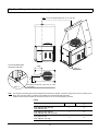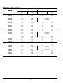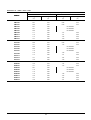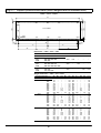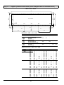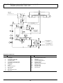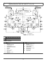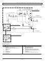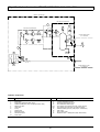
1
S [004-016]
HIGH PERFORMANCE AIR COOLED CHILLER
SERVICE MANUAL
English
Cod. 272491
Rev. 25.05.2005
Issued by T.D.Service
Caution
It
S
S
S
is recommended that:
the manual is retained for the entire service life of the machine;
the user reads the manual carefully before carrying out any operations on the machine;
the machine is used exclusively for the purpose for which it is intended; incorrect use of the machine shall release the
manufacturer from any liability.
This manual has been prepared to enable the end ---user to carry out only those operations that can be done with the panels
closed. Any operations that require the opening of doors or equipment panels must be carried out only by qualified personnel.
Each machine is equipped with an electric isolating device which allows the operator to work in conditions of safety. This
device must always be used to eliminate risks during maintenance (electric shocks, scalds, automatic restarting, moving
parts and remote control).
The panel key supplied with the unit must be kept by the person responsible for maintenance.
For identification of the unit (model and serial no.) in case of the necessity for assistance or spare parts, read the identification
labels affixed to the outside and inside of the unit.
IMPORTANT: This manual may be subject to modification; for complete and up ---to---date information the user should always consult the manual supplied with the machine.
Index
1 --
2 --
3 --
4 --
5 -6 -7 -8 --
Introduction . . . . . . . . . . . . . . . . . . . . . . . . . . . . . . . . . . . . . . . . . . . . . . . . . . . . . . . . . . . . . . . . . . . . . . . . . . . . . . . 1
1.1
1.2
1.3
1.4
---------
Foreword . . . . . . . . . . . . . . . . . . . . . . . . . . . . . . . . . . . . . . . . . . . . . . . . . . . . . . . . . . . . . . . . . . . . . . . . . . . . . . . . . . . .
Responsibility . . . . . . . . . . . . . . . . . . . . . . . . . . . . . . . . . . . . . . . . . . . . . . . . . . . . . . . . . . . . . . . . . . . . . . . . . . . . . . . .
Inspection . . . . . . . . . . . . . . . . . . . . . . . . . . . . . . . . . . . . . . . . . . . . . . . . . . . . . . . . . . . . . . . . . . . . . . . . . . . . . . . . . . .
General description . . . . . . . . . . . . . . . . . . . . . . . . . . . . . . . . . . . . . . . . . . . . . . . . . . . . . . . . . . . . . . . . . . . . . . . . . . . .
1
1
1
1
Preliminary Operations . . . . . . . . . . . . . . . . . . . . . . . . . . . . . . . . . . . . . . . . . . . . . . . . . . . . . . . . . . . . . . . . . . . . 1
2.1
2.2
2.3
2.4
2.5
-----------
Operating limits . . . . . . . . . . . . . . . . . . . . . . . . . . . . . . . . . . . . . . . . . . . . . . . . . . . . . . . . . . . . . . . . . . . . . . . . . . . . . . .
Sound pressure levels . . . . . . . . . . . . . . . . . . . . . . . . . . . . . . . . . . . . . . . . . . . . . . . . . . . . . . . . . . . . . . . . . . . . . . . . .
Transport . . . . . . . . . . . . . . . . . . . . . . . . . . . . . . . . . . . . . . . . . . . . . . . . . . . . . . . . . . . . . . . . . . . . . . . . . . . . . . . . . . . .
Foundations . . . . . . . . . . . . . . . . . . . . . . . . . . . . . . . . . . . . . . . . . . . . . . . . . . . . . . . . . . . . . . . . . . . . . . . . . . . . . . . . . .
Service area . . . . . . . . . . . . . . . . . . . . . . . . . . . . . . . . . . . . . . . . . . . . . . . . . . . . . . . . . . . . . . . . . . . . . . . . . . . . . . . . . .
1
1
2
2
2
Installation . . . . . . . . . . . . . . . . . . . . . . . . . . . . . . . . . . . . . . . . . . . . . . . . . . . . . . . . . . . . . . . . . . . . . . . . . . . . . . . . 2
3.1 --3.2 --3.3 ---
Hydraulic connections . . . . . . . . . . . . . . . . . . . . . . . . . . . . . . . . . . . . . . . . . . . . . . . . . . . . . . . . . . . . . . . . . . . . . . . . . 2
Connection of the safety valve discharge . . . . . . . . . . . . . . . . . . . . . . . . . . . . . . . . . . . . . . . . . . . . . . . . . . . . . . . . . 3
Electrical connections . . . . . . . . . . . . . . . . . . . . . . . . . . . . . . . . . . . . . . . . . . . . . . . . . . . . . . . . . . . . . . . . . . . . . . . . . . 4
Start-- Up and Operation . . . . . . . . . . . . . . . . . . . . . . . . . . . . . . . . . . . . . . . . . . . . . . . . . . . . . . . . . . . . . . . . . . . 4
4.1
4.2
4.3
4.4
4.5
4.6
-------------
Initial check . . . . . . . . . . . . . . . . . . . . . . . . . . . . . . . . . . . . . . . . . . . . . . . . . . . . . . . . . . . . . . . . . . . . . . . . . . . . . . . . . .
First start---up (or after a long stop) . . . . . . . . . . . . . . . . . . . . . . . . . . . . . . . . . . . . . . . . . . . . . . . . . . . . . . . . . . . . . . .
Starting and stopping . . . . . . . . . . . . . . . . . . . . . . . . . . . . . . . . . . . . . . . . . . . . . . . . . . . . . . . . . . . . . . . . . . . . . . . . . .
Chillers serving special plants . . . . . . . . . . . . . . . . . . . . . . . . . . . . . . . . . . . . . . . . . . . . . . . . . . . . . . . . . . . . . . . . . . .
Freecooling . . . . . . . . . . . . . . . . . . . . . . . . . . . . . . . . . . . . . . . . . . . . . . . . . . . . . . . . . . . . . . . . . . . . . . . . . . . . . . . . . .
Microprocessor control . . . . . . . . . . . . . . . . . . . . . . . . . . . . . . . . . . . . . . . . . . . . . . . . . . . . . . . . . . . . . . . . . . . . . . . . .
4
5
5
5
5
5
Refrigerant and Oil Charge . . . . . . . . . . . . . . . . . . . . . . . . . . . . . . . . . . . . . . . . . . . . . . . . . . . . . . . . . . . . . . . . . 5
5.1 --5.2 ---
Refrigerant charge . . . . . . . . . . . . . . . . . . . . . . . . . . . . . . . . . . . . . . . . . . . . . . . . . . . . . . . . . . . . . . . . . . . . . . . . . . . . 5
Oil charge . . . . . . . . . . . . . . . . . . . . . . . . . . . . . . . . . . . . . . . . . . . . . . . . . . . . . . . . . . . . . . . . . . . . . . . . . . . . . . . . . . . 6
Safety Devices Settings . . . . . . . . . . . . . . . . . . . . . . . . . . . . . . . . . . . . . . . . . . . . . . . . . . . . . . . . . . . . . . . . . . . . 6
6.1 ---
Setting thermostatic expansion valve . . . . . . . . . . . . . . . . . . . . . . . . . . . . . . . . . . . . . . . . . . . . . . . . . . . . . . . . . . . . . 6
Maintenance . . . . . . . . . . . . . . . . . . . . . . . . . . . . . . . . . . . . . . . . . . . . . . . . . . . . . . . . . . . . . . . . . . . . . . . . . . . . . . 7
7.1 --7.2 ---
Spare parts . . . . . . . . . . . . . . . . . . . . . . . . . . . . . . . . . . . . . . . . . . . . . . . . . . . . . . . . . . . . . . . . . . . . . . . . . . . . . . . . . . 7
Dismantling the unit . . . . . . . . . . . . . . . . . . . . . . . . . . . . . . . . . . . . . . . . . . . . . . . . . . . . . . . . . . . . . . . . . . . . . . . . . . . 7
Options and Accessories . . . . . . . . . . . . . . . . . . . . . . . . . . . . . . . . . . . . . . . . . . . . . . . . . . . . . . . . . . . . . . . . . . . 7
8.1
8.2
8.3
8.4
8.5
-----------
Pump set . . . . . . . . . . . . . . . . . . . . . . . . . . . . . . . . . . . . . . . . . . . . . . . . . . . . . . . . . . . . . . . . . . . . . . . . . . . . . . . . . . . .
Water chiller with partial heat recovery (20%) . . . . . . . . . . . . . . . . . . . . . . . . . . . . . . . . . . . . . . . . . . . . . . . . . . . . . .
Water chiller with total heat recovery (100%) . . . . . . . . . . . . . . . . . . . . . . . . . . . . . . . . . . . . . . . . . . . . . . . . . . . . . . .
Hydraulic circuit accessories . . . . . . . . . . . . . . . . . . . . . . . . . . . . . . . . . . . . . . . . . . . . . . . . . . . . . . . . . . . . . . . . . . . .
Water chiller with inertia tank . . . . . . . . . . . . . . . . . . . . . . . . . . . . . . . . . . . . . . . . . . . . . . . . . . . . . . . . . . . . . . . . . . . .
7
7
8
8
8
Tables . . . . . . . . . . . . . . . . . . . . . . . . . . . . . . . . . . . . . . . . . . . . . . . . . . . . . . . . . . . . . . . . . . . . . . . . . . . . . . . . . . . . . . . . . . 9
Drawings . . . . . . . . . . . . . . . . . . . . . . . . . . . . . . . . . . . . . . . . . . . . . . . . . . . . . . . . . . . . . . . . . . . . . . . . . . . . . . . . . . . . . . 15
Circuits . . . . . . . . . . . . . . . . . . . . . . . . . . . . . . . . . . . . . . . . . . . . . . . . . . . . . . . . . . . . . . . . . . . . . . . . . . . . . . . . . . . . . . . . 26
1 --- Introduction
Each unit is completely factory assembled; after evacuation, the
necessary quantity of refrigerant is added to the refrigerant circuit(s) and the unit is tested.
All the units are equipped with one or two independent refrigerating circuits, each one composed of: an air ---cooled condenser,
a hermetic Scroll compressor and a braze ---welded plate evaporator. The components of the liquid line are the charging valves,
filters---dryers, solenoid valve, shut---off valve, moisture indicator
and thermostatic expansion valve.
The hydraulic circuit is made up of hydraulic lines both in steel
and flexible EPDM rubber, connected by fittings and threaded
joints, a flow switch (optional) and, in the freecooling versions,
chilled water coils and a three ---way valve.
The hermetic scroll compressors are complete with the following
protection/safety devices: oil heater (if necessary), electronic
protection monitoring the temperature of the motor windings
and the direction of rotation (the latter may be enclosed in the
electronics of the compressor or external, depending on the
model). The ”MATRIX S” water chillers are controlled by the ”MICROFACE” microprocessor, managing all the unit operating
conditions. The user can change and/or modify the operating
parameters through the display keyboard installed on the electrical panel.
The electrical control board is equipped with all the safety and
operating devices required for reliable operation. The compressor motors are equipped with protection on all three phases and
are started by three ---pole contactors.
1.1 --- Foreword
This handbook is aimed at enabling both the installer and the operator to carry out the correct installation, operation and maintenance of the refrigerating machine, without damaging it or causing injuries to the relevant staff.
The handbook is thus an aid for the qualified staff in the arrangement of the specific equipment for the correct installation, operation and maintenance in compliance with the local regulations
in force.
The MATRIX S water chillers can be identified as follows:
CBH004
Cooling Capacity “kW”
Nominal cooling capacity / 10
Compressor:
H Hermetic Scroll
2 --- Preliminary Operations
Version:
B Base
L Low Noise
Q Quiet
2.1 --- Operating limits
The units can operate within the indicated operating ranges (see
Tab. 5). These limits apply to new machines, subject to correct
installation and maintenance.
S Ambient air minimum temperature: ---25ûC for Superchiller,
+15ûC for Chiller without fan speed control (Operation allowed only in summer mode), ---10ûC for Chiller with continuous fan speed control (Either Triac or EC fan);
S Maximum outdoor air temperature is in relation to each model, as indicated in Tab. 5. In any case outdoor temperatures
aver 45ûC are not admitted; such limits are determined by
electrical and electronic components fitted on units;
S Maximum water flow allowed: depending on the pressure
drop corresponding to the required thermal difference (usually not lower than 3.5ûC --- 4ûC);
S Minimum allowed water flow: compatible with a sufficient
evaporation temperature, to avoid the intervention of the
safety devices (to be evaluated for a thermal difference not
higher than 8ûC);
S Temperature range of the water exiting the evaporator: 4ûC
--- 15ûC;
S Maximum temperature of the water entering the unit: 20ûC;
higher temperatures are allowed only at the system start--up and not during normal operation;
S Maximum glycol concentration: 50% (35% with the optional
pump assembly installed on the machine);
S Minimum allowed glycol concentration: depending on the
minimum temperature of the ambient air expected at the
installation site (see Tab. a);
S Maximum pressure of the hydraulic circuit: 5 bar;
S Voltage range for the electric supply: 400 V +/ --- 10%; max.
phase difference: 3%; tolerance on frequency: 1%.
Storage conditions: ---20ûC --- 45ûC for all MATRIX S models
Note:
Avoid positioning in areas with strong dominant winds that may
impair the operation and effect the indicated limits.
Execution:
C Chiller
S Superchiller
1.2 --- Responsibility
Liebert Hiross accepts no present or future responsibility for
damage to persons, things or to the machine itself due to operators’ negligence, failing to comply with the installation, operation
and maintenance instructions of this handbook, failed application of the safety norms in force for the system and the qualified
staff charged with the operation and maintenance.
1.3 --- Inspection
All units are fully assembled and wired in the manufacturing
plant. Before shipment they are charged with the necessary
quantities of refrigerant and oil and then tested at the operating
conditions normally required by the customer. The machine’s
hydraulic circuit is equipped with drain plugs and open vent
valves; the free ---cooling coils are supplied dry to avoid possible
problems due to frost in the storage period. Immediately inspect
the machine carefully on delivery to check for damage during
transportation or missing components; possible claims must be
made immediately to the carrier and the factory or its representative.
1.4 --- General description
MATRIX S units with air ---cooled condensers have been designed and manufactured for producing chilled water.
They are also available in versions with a built---in freecooling
module, in versions with heat recovery for simultaneous heating
of thermal circuit water, with a pump assembly installed on the
machine and/or inertial buffer tank inside the machine; the chilling units can be equipped with several options indicated in the
price list.
The ”MATRIX S” product line has been designed utilising the
state ---of ---the ---art techniques available nowadays in the industry, and includes all the components necessary for automatic
and efficient operation.
2.2 --- Sound pressure levels
The Tab. 6 shows the noise data for the units in standard configuration (without pumps), operating continuously and measured
according to the ISO 3744 norm, in free field conditions.
The highest noise levels are detected on the condenser coil side.
1
Note:
Avoid positioning in areas with possible reverberation of the
sound waves, which can adversely effect the noise levels.
8) Install, at the highest points in the circuit, apparatus which
allows the bleeding of air and possibly the filling of glycol;
9) Place a drain valve at the lowest point in the circuit and immediately at the outlet of the water chiller;
10) Install a water filling set including the following:
a) filling water meter;
b) manometer;
c) non ---return valve;
d) air separator;
e) removable supply tube, which must be disconnected
after each charge/top ---up;
11) For maximum protection ensure that all tubing exposed to
low outdoor temperatures is fitted with anti ---freeze heaters
and insulated using closed cell synthetic rubber (elastomer);
12) The circuit must include an expansion vessel (with safety
valve) of suitable capacity;
13) Connect the lines avoiding stresses on the machine inner
parts.
Note:
If the water chiller is complete with an expansion vessel (supplied as an option), check if the capacity is enough, and install
a second vessel in the circuit, if required (see par. 8.4).
Follow the indications in Fig. c for the correct sizing.
Note:
The whole circuit must contain a water volume suitable for the
capacity of the installed chiller. Check if the inertial capacity given by the sum of the hydraulic volume inside the machine (including the volume of the optional interna tank, if fitted) and the
system volume is sufficient, or possibly install a tank in the circuit.
Follow the indications in Fig. b for the correct sizing.
Note:
The hydraulic circuit must ensure a constant water supply to the
evaporator in every operating condition. Otherwise, the compressors may be damaged by repeated returns of liquid refrigerant on their suction.
Note:
The water flow switch is a compulsory safety component that
must be installed and correctly wired to the Matrix S chillers,
otherwise the guarantee will be invalidated.
It is installed, as standard, on units with the optional on ---board
pump set, and is available as a option for units without pumps
on board: in the latter case the flow switch, if not installed on the
machine, can be installed on the hydraulic circuit by the installer,
but it is compulsory that it is wired to the electric panel terminal
board, as indicated on the wiring diagram.
2.3 --- Transport
Handle the unit by lifting it with a crane from above;
The lifting holes are positioned in the frame’s base (when lifting, use spreader bars to protect the sides, see Fig. 2 and
Fig. 3).
Note:
Place the lifting tubes in the holes in the base indicated by ”LIFT
HERE”. Lock the ends of the tubes with the locking pins and
splits pins as shown in Fig. 2. As an alternative, shackles/hooks
(optional) fastened at the base ends can be used as a lifting system: in this case the lifting point must be on the vertical line
passing through the machine’s centre of gravity (as indicated in
Fig. 3) to prevent any load imbalance.
The capacity of the lifting gear must be adequate to lift the load
in question. Check the weight of the units, the capacity of the lifting gear and ropes and the condition and suitability of the aforementioned equipment.
S
S
2.4 --- Foundations
The unit must be placed on a level surface which will support
its weight.
S If necessary, position the unit on suitable anti ---vibration supports that can be supplied as an option (in rubber or spring --type). Refer to the manual ”Installation of the spring anti --vibration supports” for their correct positioning.
S When positioned, level the unit.
Note:
For weight distribution see Fig. 4 and Fig. 5.
Note:
The weights and their distribution refer to standard units without
options; if the pump assembly, or other options are installed on
the machine, add the weights of the installed accessories to
those of the standard units (see Tab. 8).
S
2.5 --- Service area
S
S
S
In order to allow free air flow and maintenance of the unit, a
minimum area must be left free of obstructions around the
unit (see Fig. 1).
The hot air expelled by the fans must be allowed to rise unimpeded by obstacles for a minimum height of 2.5 m.
Avoid recirculation of hot air between the suction and discharge, otherwise the unit performance may be impaired or
the standard operation can be interrupted.
3.1.2 -- Addition of water and ethylene glycol
Very important:
Add water and ethylene glycol to the circuit with a % depending
on the minimum temperature of the outside air expected at the
installation site. Do not exceed the nominal operating pressure
of the circuit’s components.
Notes:
S To avoid stratification run the circulation pump for at least 30
minutes after adding any glycol.
S After adding water to the hydraulic circuit always disconnect the water supply coming from the sanitary supply;
this avoids the danger of glycol entering the sanitary water
system.
S After any topping ---up of the water check the concentration
and add glycol if necessary.
3 --- Installation
3.1 --- Hydraulic connections
3.1.1 -- Hydraulic circuit construction (Fig. a)
The piping must be connected to the chiller. Construct a chilled
water circuit as described below, see Fig. a:
1) Place shut---off valves within the circuit to allow servicing;
2) Install a pump system suitable for the flow rate required at
a pressure head equal to the sum of all the pressure drops
(see project data).
Matrix S chillers can be equipped, upon request, with
pumps having performance as indicated in Tab. 8;
3) Install manometers at the chiller inlet/outlet;
4) Install thermometers at the chiller inlet/outlet;
5) Connect the pipes to the chiller by flexible joints to avoid
transmitting vibrations and to balance the thermal expansion; proceed in the same way even if the pump set is outside the chiller;
6) It is useful to include a water pressure switch to give an early
warning of low water pressure;
7) Place a mesh filter at the inlets of the pump and water chiller
(Can be supplied as an optional accessory ---Not fitted);
3.1.3 -- Water-- glycol mixture
Water ---glycol mixtures are used as the thermal carrier fluid in
very cold climates or with temperatures below zero degrees centigrade. Determine the ethylene glycol % which must be added
to the water, with the assistance of Tab. a.
2
Tab. a -- Ethylene glycol to be added to water (% in
weight of total mixture)
Ethylene glycol
(% in weight)
0
10
20
30
40
50
Freezing temperature, ûC (*)
0
---4.4
---9.9
---16.6
---25.2
---37.2
Mixture density at
20ûC (*), kg/l
---
1.017
1.033
1.048
1.064
1.080
ALWAYS CHARGE THE HYDRAULIC CIRCUIT WITH THE REQUIRED GLYCOL % NECESSARY FOR THE MINIMUM AMBIENT TEMPERATURE AT THE INSTALLATION SITE. FAILING
TO COMPLY WITH THIS INSTRUCTION SHALL INVALIDATE
THE UNIT WARRANTY.
3.2 --- Connection of the safety valve discharge
Safety valves are installed on the high pressure side of the refrigeration circuit(s): the discharge of these valves must be conveyed outside through a suitable pipe, having a diameter of at
least that of the valve outlet, without burdening the valve body.
Convey the discharge to areas where the jet cannot harm
people and the surrounding environment.
(*) Values are for Shell antifreeze 402. For different brands, check
manufacturer’s data.
For the chiller internal water volume refer to Tab. 1. If the optional
buffer tank is installed on the machine, add the tank hydraulic
volume.
Fig. a -- Ideal chilled water circuit
1
6
3
4
7
2
5
3
4
1
8
T
T
CHILLER
5
disconnect after charge
5
9
flow
Vpt
Tank
USER
9
10a
10b
10c
10d
10e
1
1
11
12
Fig. b -- Inertia tank sizing
The total optimum hydraulic volume of the system where the Matrix S chiller is installed can be calculated by the
following formula:
V=
43 x Rt
Xd
where:
--- V=minimum required total water volume expressed in litres
--- Rt=refrigeration capacity expressed in kW
--- Xd=differential band set on the control and expressed in degrees centigrade
Please note that the sum of the hydraulic volume of the Matrix S chiller (Vm) plus the volume of the hydraulic circuit
connected to it (Vpc) must be greater than, or equal to the minimum required total water volume (V). If this condition is not satisfied, it is necessary to install an inertia tank (Vpt, as indicated in the Fig. a) with a volume at least
equal to the following value: Vpt=V ---Vm ---Vpc
3
Fig. c -- Sizing of the expansion vessel
The total volume of the expansion vessel is calculated with the following formula:
V=
Cxe
Pi
1 -Pf
where:
--- C=quantity of water inside the system expressed in litres
--- e=water expansion coefficient, with water at 10ûC as a reference
--- Pi=absolute pressure of initial charging, equivalent to the vessel pre ---charge pressure (typical value
2.5 bara)
--- Pf=absolute final tolerated pressure, lower than the operating pressure of the safety valve calibration
pressure (typical value 4.0 bara).
Use the values of the water expansion coefficient indicated in the table below:
H2O T [°C]
Density [kg/m3]
10
999.6
--- --- ---
20
997.9
0.0017
30
995.6
0.0040
40
992.2
0.0075
50
988.1
0.0116
Expansion coefficient “e”
3.3 --- Electrical connections
Operate (open) the main switch before carrying out any maintenance work on electrical components.
Note:
It is forbidden to work on the electrical components without
using insulating platforms, and in the presence of water or fog
or mist.
Note:
The supply to the external pump assembly must be made before
starting the chiller and must be kept on as long as the chiller is
in use. Incorrect operation will cause the unit to lock ---out because of the internal protections (flow switch intervention).
Note:
The compressors are equipped with an electronic protection device blocking their start if the phase sequence is not correct, or
stopping their operation if a thermal relay intervenes. This device
is essential for the integrity of the mechanical and electrical components of the compressors. Reset the standard functions by
isolating this device and removing the causes of the lock ---out.
Note:
The chillers are equipped with their own microprocessor control
adjustment. The use of the remote ON ---OFF input (located in
the electric panel terminal board) as a system temperature control element is forbidden.
1) Before proceeding with the electrical connections, ensure
that:
S all electrical components are undamaged;
S all terminal screws are tight;
S the supply voltage and frequency are in accordance with
the rating (with tolerance in accordance with IEC 8---6
norms, March 1990)
S the allowed phase to phase variability is 3% maximum
(see Fig. d). Variability in excess of 3% invalidates the
guarantee.
2) Supply cable connections (see Tab. 4):
S Connect the cable to the supply terminals.
S Use appropriately sized 3---pole cable. An earth wire
must also be connected.
S After having opened the passage in the framework (pre --punched knock ---outs) for the supply line entry, restore
the original degree of protection using suitable accessories for the wiring and junction boxes.
Fig. d -- Example of calculating phase
to phase variability
1) The 400 V supply has
the following variability:
RS = 388 V
ST = 401 V
RT = 402 V
4 --- Start---Up and Operation
R S T
4.1 --- Initial check
1) Check all water connections.
2) Open the shut---off valve on the liquid line.
3) Ensure that the intake pressure is higher than 4.0 bar; if this
is not the case, prolong pre ---heating of the compressor (if
possible) and check that the refrigerant shut---off valve is
properly sealed, see Fig. 10 and Fig. 11.
4) Open all isolating valves and/or water ball valves.
5) In case of climates with temperatures below zero degrees C,
make sure the chilled water circuit is filled with the correct
concentration of water/glycol.
6) Bleed all air out of the chilled water circuit.
7) Verify the water flow rate and its direction.
8) Ensure that the thermal load is sufficient for start---up.
Caution:
The ambient air temperature probe must be positioned in the
shade and protected against the weather.
2) The average voltage is:
388 + 401 + 402
= 397
3
3) The maximum deviation from the average is:
402 --- 397 = 5 V
4) The phase to phase variability is:
5
x 100 = 1.26 (acceptable)
397
Note:
The power supply should never be disconnected, except when
performing maintenance.
4
4.2 --- First start ---up
4.6 --- Microprocessor control
(or after a long stop)
Consult the ”Microface and Hiromatic” Service Manual.
Operate as follows:
1) At least 8 hours before the start ---up, power the crankcase heaters (if any, see point 4) by setting the main isolator switch ON. Make sure the auxiliary circuit has been
powered and check the operation (a fault due to an incorrect procedure will invalidate the compressor guarantee).
2) Open the valves of the refrigeration circuit that had been
closed before the initial check.
3) Check the machinery supplying the thermal load connected
with the unit and start the system pump(s).
4) MAKE SURE THE COMPRESSOR OIL HAS BEEN HEATED
FOR AT LEAST 8 HOURS; start the unit only then. In the
units not equipped with crankcase heaters (Chillers for summer operation only, without modulating fan speed control),
the start must be carried out in the warm season only (external T > 15ûC), and thus oil pre ---heating is not necessary.
5) Make sure the fans rotate in the correct direction (anticlockwise): check the electrical connections, if necessary.
6) Make sure the pumps rotate in the correct direction.
7) During the unit start ---up an inlet water temperature
higher than 20ûC is allowed. Under standard operating
conditions check that the limits indicated in paragraph
2.1 are not exceeded.
8) Check the correct operation of the control and safety devices.
9) Check the outlet temperature of the chilled water (check if
the set---point set on the controller is reached).
10) Check the compressor oil level.
11) With the compressor at full load, check there are no
bubbles visible in the frefrigerant sight glass. If there are any,
charge the unit according to par. 5.
5 --- Refrigerant and Oil Charge
All work on pipes or components of the refrigerating circuit under pressure must be exclusively carried out by qualified staff,
competent in such works.
5.1 --- Refrigerant charge
WHILST REPAIRING THE REFRIGERATING CIRCUIT RECOVER ALL THE REFRIGERANT IN A CONTAINER: DO NOT
ALLOW IT TO ESCAPE. NEVER USE THE COMPRESSOR
FOR THE SYSTEM VACUUM (THIS INVALIDATES THE
WARRANTY).
S The unit is delivered charged according to the Tab. 7.
Warning for the refrigerant charge:
S Ensure there are no refrigerant leaks.
S Check the refrigerant type in the refrigeration circuit: a unit
originally charged by the manufacturer with R407C cannot
be charged with R22 and vice versa; possibly apply to the
Technical Support Department.
S Charge with the compressor in operation, connecting the
cylinder with the charge connector after the thermostatic expansion valve.
Flush the connection pipe between the cylinder and the
charging point; tighten the seal joint and then start charging
the unit. It is imperative that the cylinder is weighed both before and after the operation.
S For the units with R407C the refrigerant charge must be
made exclusively with liquid refrigerant.
S Charge the unit until the bubbles in the sight glass have disappeared and the working conditions of the entire refrigeration circuit have returned to normal (sub ---cooling and superheating within the limits indicated below).
S Measure the superheating as follows:
1) Detect the temperature on the suction line, close to the
bulb of the thermostatic expansion valve, using a contact
thermometer.
2) Connect a pressure gauge (by max. a 30---cm pipe) with
the Schraeder connection and read the corresponding
saturated evaporating temperature.
3) The superheating is the difference between the two
readings.
4) For the units with R407C refer to the pressure gauge
scale indicated with the initials D.P. (Dew Point)
S Verify that the superheating is 5ûC --- 8ûC.
S Measure the sub ---cooling as follows:
1) Detect the temperature on the liquid line using a contact
thermometer.
2) Connect a pressure gauge (by max. a 30---cm pipe) with
the Schraeder connection on the liquid line and read the
corresponding saturated condensing temperature.
3) The sub ---cooling is the difference between the two readings.
4) For the units with R407C refer to the pressure gauge
scale indicated with the initials B.P. (Bubble Point)
S Verify that at the condenser outlet, sub ---cooling is 3ûC --5ûC.
IT IS IMPORTANT TO CARRY OUT CHARGING CORRECTLY.
An excess of refrigerant causes an increase in sub ---cooling and
consequent operating difficulties in the hot season; a shortage
of charge generates an increase in superheating and possible
compressor stoppages. Whenever work is carried out on the
unit, ensure afterwards that the working conditions are correct,
checking sub ---cooling and superheating.
4.3 --- Starting and stopping
ALWAYS ENSURE THAT THE COMPRESSOR OIL HAS BEEN
PREHEATED.
FOR BRIEF STOPPAGES MAINTAIN THE SUPPLY TO THE
CRANKCASE HEATER (IF ANY).
S Start the unit setting the Microprocessor switch ON.
S Stop the unit setting the Microprocessor switch OFF.
S In case of long stops, turn the machine off using the Microprocessor switch OFF.
In this case the compressor crankcase heaters (if any) remain powered.
S For seasonal shutdown of the unit operate the main switch
located on the main electrical power supply. This will disconnect the compressor crankcase heaters.
4.4 --- Chillers serving special plants
The units are capable of cooling a water ---glycol mixture to temperatures close to 0ûC without the need for significant modifications. In the case of modification, the set values of the safety and
control components must also be changed. This can be carried
out in the factory (at the time of testing) or at the time of installation, only by qualified and authorised personnel.
4.5 --- Freecooling
The “freecooling” is a system of pre ---cooling and/or cooling the
water/glycol mixture using ambient air when the latter is at a temperature below the return mixture temperature. If the outside
temperature is sufficiently low to dissipate the entire heat load,
the refrigeration compressors automatically switch off, and the
mixture’s temperature is controlled by the fan speed adjustment.
If the mixture temperature is too high for freecooling, the compressors will operate as long as necessary to ensure the correct
water/glycol mixture temperature.
5
5.2 --- Oil charge
1) Take a clean, dry, transparent container (with volume calibrations) and fill it with at least twice the amount of oil required.
2) Isolate the compressor by closing the cock on the liquid line.
3) Connect to the fittings on the compressor body (Schraeder
valves) and empty it of refrigerant until atmospheric pressure (1 bar) is reached.
4) Using a pipe, connect the oil container to the oil service fitting
on the lower part of the compressor.
5) Open the oil service cock, lifting the container, so that the oil
flows by gravity.
6) Charge the required quantity of oil (make sure the tube always remains below the oil level in the container).
7) Stop the oil flow by closing the oil service fitting, open the
shut---off cock on the refrigerating circuit and restore the
drained refrigerant charge.
Contact the Technical Support Department for the specifications
of the oil to be used for topping up; the oil changes according to
the type of used refrigerant.
NEVER MIX DIFFERENT OILS TOGETHER. CLEAN THE PIPING COMPLETELY BEFORE CHANGING THE TYPE OF OIL
USED.
TOP---UPS OF UP TO 20---30% OF THE TOTAL AMOUNT OF
OIL CONTAINED IN THE COMPRESSOR CRANKCASE ARE
PERMITTED; FOR LARGER PERCENTAGES CONTACT THE
TECHNICAL SUPPORT DEPARTMENT.
5.2.1 -- Procedure for oil topping -- up
If there has been any loss of oil then this must be topped up as
follows:
6 --- Safety Devices Settings
The water chiller has already been tested and set up by the manufacturer. The following setting values are suggested in the field.
COMPONENT
SETTING
NOTES
set
diff.
Operation with R407C/R22
(standard factory setting):
Low pressure switch (LP)
START
DIFF.
STOP
0.2 1.5
0.5
5
bar
: 3.6 bar
: 0.8 bar
: 2.8 bar
bar
Operation with R407C/R22
(standard factory setting):
High pressure switch (HP)
STOP
START
DIFF.
: 26 bar
: 20 bar
: 6 bar (fixed)
reset
The settings for the safety valves installed on the machine are indicated below:
MODELS
SETTINGS
004 --- 204 --- 206 --- 207 --- 008
28 bar
006 --- 007 --- 011 --- 014 --- 016
29 bar
6.1 --- Setting
valve
thermostatic
expansion
SAFETY VALVE
HP side
4) The superheating must be 5ûC --- 8ûC; if not, set the expansion valve as follows:
a) Remove the protective cover;
b) Turn the adjustment screw to return to the optimum values, tightening it in a clockwise direction to increase the
superheating, or slackening it to reduce the superheating.
c) Wait about 10 minutes;
d) Measure the superheating and repeat the operation if
necessary.
N.B:
If the superheating is too low, there is a risk of poor lubrication
and consequent breakage of the compressor as a result of pressure shock.
If the superheating is too high the output of the system is limited
and the compressor overheats.
THIS OPERATION MUST BE PERFORMED BY AN EXPERIENCED REFRIGERATION TECHNICIAN.
Before beginning this adjustment be sure that the refrigerant
charge is correct, checking the the sub ---cooling (3ûC --- 5ûC, as
specified in par. 5.1).
The valve has already been factory ---set and should be reset
when the superheating is not between 5ûC --- 8ûC, as follows:
1) Important:
Ensure that the instructions in par. 5.1 have been carried out.
2) Allow the compressor to operate for 15 mins.
3) Measure the superheating as follows:
a) Connect a manometer to the Schraeder connection located on the evaporator outlet tube, and read the manometric temperature on the scale for the refrigerant used
(for the units with R407C refer to the pressure gauge
scale indicated with the initials D.P. = Dew Point).
b) Using a contact thermometer, measure the temperature
on the tube coming out of the evaporator, next to the
socket used for the manometer.
c) The superheating is the difference between the two
readings (b ---a).
6
7 --- Maintenance
7.1 --- Spare parts
The Maintenance Programme below must be carried out by a
qualified technician, preferably working under a maintenance
contract.
Before any intervention on the unit or accessing the inner components (removing the outer panels), always ensure the machine is switched off. If the rear panels are removed (coil compartment) wait for the fan(s) to come to a complete stop before
accessing the compartment; if the front panels are removed, pay
special attention when working near the compressor upper part
and the discharge line: they are very hot; possibly wait for them
to cool. Be very careful when operating close to the finned coils,
as the fins are very sharp. Do not remove the fan protection grille
before electrically isolating the whole machine. Do not insert
foreign matter through the fan protection grille. After the maintenance interventions, always close the unit with the suitable
panels, fastened by the tightening system.
The use of original spare parts is recommended.
When placing an order refer to the ”Component List” enclosed
with the machine and quote the unit model no. and serial no.
7.2 --- Dismantling the unit
The machine has been designed and built to ensure continuous
operation.
The working life of some of the main components, such as the
fans and the compressors, depends on the maintenance that
they receive.
If the unit has to be dismantled, the job must be done by skilled
refrigeration technicians.
The refrigerant and the lubricating oil in the circuit must be disposed of in conformity with the laws in force in your country.
Maintenance programme -- Monthly check
FANS
S
S
Check that the fan motor rotates freely without any abnormal noise, and ensure that the
bearings are not running hot.
Also check the current absorption.
S
Check the conditions of the filters (if they are supplied); if necessary clean them (including
the electrical panel ventilation filter).
Check the condenser coils and clean if necessary with compressed air or soft brushes.
CONTROL
S
Check that the control equipment, LEDs and display are operating correctly.
ELECTRICAL CIRCUIT
S
S
Check the electrical supply on all phases.
Ensure that all electrical connections are tight.
S
Check the condensing and the evaporating pressures (to be done by a refrigeration technician).
Check the compressor’s current absorption, the delivery temperature and possible unusual
noises.
Check the refrigerant charge by means of the sight glass.
Check that the safety devices operate correctly.
Check the correct operation of the thermostatic valve (superheating between 5ûC --- 8ûC).
Check that the oil level indicated by the compressor sight glass is higher than the min. value.
CONDENSER AND AIR FILTER
S
S
REFRIGERATION CIRCUIT
S
S
S
S
CHILLED WATER CIRCUIT
S
S
S
S
S
S
S
Ensure that there are no water leaks.
Bleed any air out of the hydraulic circuit using the bleed valves.
Verify that the water flow rate is correct.
Check the inlet --- outlet liquid temperature and pressure.
Check the correct operation of the three--- way valve (Versions with free--- cooling only).
Check if the system is charged with the specified glycol percentage and that no ice has
formed in the hydraulic circuit.
Check the evaporator cleanliness.
8 --- Options and Accessories
8.1 --- Pump set
Temperatures of the standard pumped fluid not lower than
4°C.
The hydraulic circuit includes, for each pump, a suction shut---off
valve and a delivery check valve if two pumps are installed, or
suction and delivery shut---off valves if a single pump is installed.
In the electrical panel there are automatic circuit breakers for
each pump; the microprocessor control manages the operating
rotation between the two pumps and start---up of the stand ---by
pump if the primary pump fails.
For the technical features of the pumps and the hydraulic schematic see Tab. 8, Fig. 12, Fig. 13, Fig. 14 and Fig. 15.
S
The centrifugal pump units are direct driven, with close --coupled motors and a single shaft; the induction motor has 2
poles with IP 54 protection and class F insulation.
The materials used for the pump main components are:
S Pump body in plastic material PA 6.6 (cast iron in all high
pressure freecooling versions and on model 016 in the Chiller high head pressure version and Superchiller standard
head pressure version);
S Impeller in in plastic material PPO (stainless steel in all high
pressure freecooling versions and on model 016 in the Chiller high head pressure version and Superchiller standard
head pressure version);
S Stainless steel shaft;
S Graphite impregnated ceramic mechanical seal (EPDM in
all high pressure freecooling versions and on model 016 in
the Chiller high head pressure version and Superchiller
standard head pressure version), suitable for the use of mixtures containing ethylene glycol.
The pump units have been chosen and sized to operate within
specific limits, namely:
S Water / ethylene glycol mixtures up to 65% / 35% by weight;
8.2 --- Water chiller with partial heat
recovery (20%)
This option enables the recovery of up to 20% of the heat normally rejected by the condensers. The system does not require any
adjustment and is made up of plate heat exchangers installed
on each circuit before the condenser. The exchangers are protected by a suitable anti ---frost heater that operates when the system is stopped. It is recommended that a safety valve be
installed in the hydraulic circuit to avoid hazards due to overpressures, if there is no water flow through the recuperator.
7
8.5 --- Water chiller with inertia tank
The water temperature at the recuperator inlet (in stable operating conditions) must be in the range of 25ûC --- 45ûC, with an outlet differential of between 3.5ûC --- 8ûC.
The machine can be supplied complete with a buffer tank; it performs the inertial stabilizer function, for better compressor operation, summed up in the following two points:
S it reduces the frequency of the compressor peaks, which is
higher the lower the system thermal inertia, improving their
performance;
S it naturally eliminates the operational problems caused by
sudden load variations (shown by variations of the chilled
water temperature).
8.3 --- Water chiller with total heat recovery
(100%)
All heat discharged by the unit to the condenser is recovered.
The system includes an additional refrigerating circuit made up
of a three ---way solenoid valve, supplying --- in case of hot water
demand --- a plate exchanger, usually by ---passed and sized so
as to discharge all condensing heat (also installed before the
finned air condenser in series with it); a check valve, a liquid receiver at the exit of the finned air condenser working as storage
for the needed additional refrigerant charge (see refrigerating
scheme). The recuperator is insulated with closed cell polyurethane and is equipped with heaters activated when the recuperator is deactivated to prevent frost in winter with the system
stopped or not perfectly drained.
The operation in total recovery mode is enabled by an external
contact. The Microface control will simultaneously suit the fan
speed changing the fan speed setpoint differently from the standard operation without recovery (practically slowing the fans
down till they switch off); anyway, the operation in recovery
mode is enabled also without load at the users. Indeed, if the users do not demand heat, the water flowing to the condenser
reaches a temperature that does not enable the total condensation of the compressed gas, and the remaining portion of the
phase change can thus take place in finned coil without interrupting the recovery process through the intervention of the machine safety devices.
If the plate exchanger is supplied with too cold water, or if the system is not preset by the installation technician with a three or
two---way proportional adjustment valve for the exchanger bypass (indispensable for cold starts, see following “Recommended hydraulic circuit” ), the condensing pressure tends to
decrease too much; a prolonged condition of low condensing
temperature below the safety threshold leads the Microface microprocessor control to disable the heat recovery, protecting the
system from any possible malfunctioning.
The buffer tank is supplied insulated, with a drain valve, vent
valve and connection for immersion electric heaters; maximum
operating pressure 6 bar.
Built in carbon steel and coated with anti ---condensation insulation. It can be installed in all MATRIX S versions inside the coil
compartment.
Mod. 004 ---006 ---007 technical data
S Internal volume:
200 litres
S Net weight:
110 kg
S Working weight: 310 kg
Mod. 008 ---011 ---014 ---016 technical data
S Internal volume:
400 litres
S Net weight:
140 kg
S Working weight: 540 kg
Mod. 204 ---206 ---207 technical data
S Internal volume:
160 litres
S Net weight:
100 kg
S Working weight: 260 kg
Fig. e -- Recommended hydraulic circuit
Heat recovery
users
Heat recovery
exchanger
8.4 --- Hydraulic circuit accessories
Made up of an expansion vessel (pre ---charged at 1.5 bar, max.
operating pressure 10 bar) and a safety valve, set at 5 bar. Their
position in the hydraulic circuit is illustrated in Fig. 12, Fig. 13,
Fig. 14 and Fig. 15.
S Expansion vessel volume: 8 litres for all units.
It is recommended that the total required expansion vessel capacity is always checked, depending on the unit’s internal hydraulic volume (with the volume of the buffer tank, if installed),
the user circuit volume, the glycol percentage in the mixture, and
the expected maximum temperature variation of the mixture.
The water flow switch is a compulsory device protecting the unit.
It is installed, as standard, on units with the optional on ---board
pump set, and is available as a option for units without pumps
on board: in the latter case the flow switch, if not installed on the
machine, must be installed on the hydraulic circuit by the installer and wired to the electric panel terminal board, as indicated on
the wiring diagram.
8
Tab. 1 --- Internal hydraulic volume
Unit volume (*) [l]
Model
004
CBH
CLH
CQH
Unit volume (*) [l]
Model
8
004
27
006
9
006
35
007
10
007
44
204
10
204
30
206
10
206
37
207
13
207
47
008
24
008
77
011
27
011
92
014
30
014
110
016
46
016
144
004
8
004
27
006
9
006
43
007
14
007
55
204
10
204
30
206
10
206
45
207
18
207
59
008
24
008
77
011
27
011
107
014
38
014
134
016
46
016
144
004
8
004
34
006
13
006
54
007
14
007
55
204
10
204
37
206
15
206
56
207
18
207
59
008
24
008
88
011
35
011
131
014
38
014
134
016
46
016
169
SBH
SLH
SQH
(*) Add the tank’s volume for the units with optional buffer tank
Tab. 2 --- Partial heat recovery (20%)
004
204
006
206
007
207
008
011
014
016
kW
10,8
14,8
18,2
21,6
29,6
36,4
44,3
l/s
0,516
0,707
0,870
1,032
1,414
1,739
2,117
kPa
8
11
14
8
11
14
21
1”
11/
Model
Heating capacity
Water flow
Water pressure drop
Water connections
BSP---T
1”
1”
4”
11/
4”
11/
4”
11/4”
Working conditions: outdoor temperature 35ûC, water inlet/outlet 12/7ûC (Chiller versions), glycol mixture 30% inlet/outlet 15/10ûC (SuperChiller versions). Heat recovery conditions: water inlet/outlet 40/45ûC.
Tab. 3 --- Total heat recovery (100%)
004
204
006
206
007
207
008
011
014
016
kW
53
74
91
105
144
177
223
10,65
Model
Heating capacity
Water flow
Water pressure drop
Water connections
l/s
2,53
3,54
4,35
5,02
6,88
8,46
kPa
60
70
80
60
70
80
90
BSP---T
2”
2”
2”
21/2”
21/2”
21/2”
21/2”
Working conditions: water inlet/outlet 12/7ûC (Chiller versions). Heat recovery conditions: water inlet/outlet 40/45ûC.
9
Tab. 4 --- Electrical characteristics
CBH -- R 407C
Size
Power supply
004
006
007
204
28
39
179
13.8
24
35
35
54
219
18.6
31
50
43
73
274
23.5
39
69
29
42
121
13.8
25
19
---
OA (1)
FLA
LRA
Compressors power input (1)
Compressors nominal current (1)
Compressor max. current
A
A
A
kW
A
A
Fan power input
Fan nominal current
Fan max. current
kW
A
A
SHC std. head pressure pump model (Opt.)
Std. head pressure pump mot. nom. power
Std. head pressure pump mot. max. power
Std. head pressure pump max. current
SHC high head pressure pump model (Opt.)
FHE high head pressure pump model (Opt.)
High head pressure pump mot. nom. power
High head pressure pump mot. max. power
High head pressure pump max. current
--kW
kW
A
----kW
kW
A
Electrical cable section (min.)
mm2
206
207
008
011
014
016
69
107
272
36.7
62
50
85
145
346
46.5
78
69
105
155
403
56.8
94
72
400 V / 3 Ph / 50 Hz
37
62
163
18.3
33
29
48
68
181
23.8
44
32
56
77
217
27.3
48
35
1.80
3.6
4.0
12 ---129
0.75
1.08
1.85
12 ---136
--1.10
1.44
2.67
16
12 ---136
1.10
1.44
2.67
20 ---128
--1.50
1.92
3.90
20 ---128
1.50
1.92
3.90
20 ---134
--1.85
2.45
4.61
20 ---134
1.85
2.45
4.61
--40 ---160/40
4.0
4.0
8.50
25
35
16
25
35
35
50
70
70
006
007
204
206
207
008
011
014
016
66
104
269
37.5
62
50
81
145
346
44.2
74
69
107
151
399
60.5
100
72
(1) Outdoor air temperature 35ûC; water inlet/outlet temperature 12/7ûC
CLH -- R 407C
Size
Power supply
004
---
OA (1)
FLA
LRA
Compressors power input (1)
Compressors nominal current (1)
Compressor max. current
A
A
A
kW
A
A
Fan power input
Fan nominal current
Fan max. current
kW
A
A
SHC std. head pressure pump model (Opt.)
Std. head pressure pump mot. nom. power
Std. head pressure pump mot. max. power
Std. head pressure pump max. current
SHC high head pressure pump model (Opt.)
FHE high head pressure pump model (Opt.)
High head pressure pump mot. nom. power
High head pressure pump mot. max. power
High head pressure pump max. current
--kW
kW
A
----kW
kW
A
Electrical cable section (min.)
mm2
400 V / 3 Ph / 50 Hz
27
37
177
14.3
25
35
34
52
217
18.9
32
50
42
73
274
22.5
38
69
28
40
119
14.3
26
19
36
60
161
18.6
34
29
47
68
181
22.8
43
32
54
74
214
28.5
50
35
0.95
2.2
2.4
12 ---129
0.75
1.08
1.85
12 ---136
--1.10
1.44
2.67
16
12 ---136
1.10
1.44
2.67
20 ---128
--1.50
1.92
3.90
20 ---128
1.50
1.92
3.90
20 ---134
--1.85
2.45
4.61
20 ---134
1.85
2.45
4.61
--40 ---160/40
4.0
4.0
8.50
25
35
16
25
35
35
50
70
70
004
006
007
204
206
207
008
011
014
016
25
36
176
13.6
24
35
33
53
218
17.9
30
50
42
72
273
23.3
39
69
26
39
118
13.6
25
19
64
104
269
35.6
60
50
82
142
343
46.6
78
69
102
148
396
60.0
98
72
(1) Outdoor air temperature 35ûC; water inlet/outlet temperature 12/7ûC
CQH -- R 407C
Size
Power supply
---
OA (1)
FLA
LRA
Compressors power input (1)
Compressors nominal current (1)
Compressor max. current
A
A
A
kW
A
A
Fan power input
Fan nominal current
Fan max. current
kW
A
A
SHC std. head pressure pump model (Opt.)
Std. head pressure pump mot. nom. power
Std. head pressure pump mot. max. power
Std. head pressure pump max. current
SHC high head pressure pump model (Opt.)
FHE high head pressure pump model (Opt.)
High head pressure pump mot. nom. power
High head pressure pump mot. max. power
High head pressure pump max. current
--kW
kW
A
----kW
kW
A
Electrical cable section (min.)
mm2
400 V / 3 Ph / 50 Hz
35
61
162
17.6
33
29
47
67
180
23.6
44
32
50
73
213
27.0
48
35
0.70
1.3
1.5
12 ---129
0.75
1.08
1.85
12 ---136
--1.10
1.44
2.67
16
25
(1) Outdoor air temperature 35ûC; water inlet/outlet temperature 12/7ûC
10
35
16
12 ---136
1.10
1.44
2.67
20 ---128
--1.50
1.92
3.90
25
35
35
20 ---128
1.50
1.92
3.90
20 ---134
--1.85
2.45
4.61
50
70
20 ---134
1.85
2.45
4.61
--40 ---160/40
4.0
4.0
8.50
70
SBH -- R 407C
Size
Power supply
004
006
007
204
---
OA (1)
FLA
LRA
Compressors power input (1)
Compressors nominal current (1)
Compressor max. current
A
A
A
kW
A
A
Fan power input
Fan nominal current
Fan max. current
kW
A
A
SHC std. head pressure pump model (Opt.)
FHE std. head pressure pump model (Opt.)
Std. head pressure pump mot. nom. power
Std. head pressure pump mot. max. power
Std. head pressure pump max. current
FHE high head pressure pump model (Opt.)
High head pressure pump motor power
High head pressure pump max. current
----kW
kW
A
--kW
A
12 ---136
--1.10
1.44
2.67
32 ---160/30
3.0
6.50
mm2
16
Electrical cable section (min.)
206
207
008
011
014
016
58
78
218
28.9
50
35
74
108
273
39.2
66
50
88
146
347
48.6
80
69
109
155
403
59.0
98
72
400 V / 3 Ph / 50 Hz
29
39
179
14.5
25
35
37
54
219
19.7
33
50
44
73
274
24.4
40
69
30
42
121
14.5
26
19
39
62
163
19.4
35
29
49
68
181
24.8
45
32
1.90
3.8
4.0
20 ---128
--1.50
1.92
3.90
32 ---160/30
3.0
6.50
25
35
12 ---136
--1.10
1.44
2.67
32 ---160/30
3.0
6.50
16
20 ---128
--1.50
1.92
3.90
32 ---160/30
3.0
6.50
20 ---134
--1.85
2.45
4.61
40 ---160/40
4.0
8.50
--40 ---160/40
4.0
4.0
8.50
40 ---200/75
7.5
15.50
25
35
35
50
70
70
206
207
008
011
014
016
57
75
215
30.4
52
35
69
105
270
38.9
64
50
85
145
346
47.0
78
69
109
151
399
63.0
102
72
(1) Outdoor air temperature 35ûC; 30% glycol water mixture; water inlet/outlet temperature 15/10ûC
SLH -- R 407C
Size
Power supply
004
006
007
204
---
400 V / 3 Ph / 50 Hz
OA (1)
FLA
LRA
Compressors power input (1)
Compressors nominal current (1)
Compressor max. current
A
A
A
kW
A
A
Fan power input
Fan nominal current
Fan max. current
kW
A
A
SHC std. head pressure pump model (Opt.)
FHE std. head pressure pump model (Opt.)
Std. head pressure pump mot. nom. power
Std. head pressure pump mot. max. power
Std. head pressure pump max. current
FHE high head pressure pump model (Opt.)
High head pressure pump motor power
High head pressure pump max. current
----kW
kW
A
--kW
A
12 ---136
--1.10
1.44
2.67
32 ---160/30
3.0
6.50
mm2
16
Electrical cable section (min.)
29
37
177
15.3
26
35
35
52
217
19.6
33
50
45
74
275
23.7
40
69
29
40
119
15.3
27
19
37
60
161
19.3
35
29
49
69
182
24.1
44
32
1.00
2.3
2.4
20 ---128
--1.50
1.92
3.90
32 ---160/30
3.0
6.50
25
35
12 ---136
--1.10
1.44
2.67
32 ---160/30
3.0
6.50
16
20 ---128
--1.50
1.92
3.90
32 ---160/30
3.0
6.50
20 ---134
--1.85
2.45
4.61
40 ---160/40
4.0
8.50
--40 ---160/40
4.0
4.0
8.50
40 ---200/75
7.5
15.50
25
35
35
50
70
70
206
207
008
011
014
016
53
73
213
28.7
50
35
68
104
269
37.8
64
50
86
142
343
49.9
82
69
106
148
396
62.3
102
72
(1) Outdoor air temperature 35ûC; 30% glycol water mixture; water inlet/outlet temperature 15/10ûC
SQH -- R 407C
Size
Power supply
004
007
204
400 V / 3 Ph / 50 Hz
OA (1)
FLA
LRA
Compressors power input (1)
Compressors nominal current (1)
Compressor max. current
A
A
A
kW
A
A
Fan power input
Fan nominal current
Fan max. current
kW
A
A
SHC std. head pressure pump model (Opt.)
FHE std. head pressure pump model (Opt.)
Std. head pressure pump mot. nom. power
Std. head pressure pump mot. max. power
Std. head pressure pump max. current
FHE high head pressure pump model (Opt.)
High head pressure pump motor power
High head pressure pump max. current
----kW
kW
A
--kW
A
12 ---136
--1.10
1.44
2.67
32 ---160/30
3.0
6.50
mm2
16
Electrical cable section (min.)
006
--27
36
176
14.4
25
35
35
53
218
18.8
32
50
44
72
273
24.8
41
69
27
39
118
14.4
26
19
36
61
162
18.5
34
29
49
67
180
25.1
46
32
0.75
1.4
1.5
20 ---128
--1.50
1.92
3.90
32 ---160/30
3.0
6.50
25
35
12 ---136
--1.10
1.44
2.67
32 ---160/30
3.0
6.50
16
20 ---128
--1.50
1.92
3.90
32 ---160/30
3.0
6.50
25
35
20 ---134
--1.85
2.45
4.61
40 ---160/40
4.0
8.50
35
50
70
--40 ---160/40
4.0
4.0
8.50
40 ---200/75
7.5
15.50
70
(1) Outdoor air temperature 35ûC; 30% glycol water mixture; water inlet/outlet temperature 15/10ûC
•
•
•
•
Nominal power supply = 400 V; 3 Ph; 50 Hz
Nominal power supply tolerance = 400 V ±10 %
Max. voltage unbalance = 3 %
The cables have to be sized in compliance with local standards and according to the type and characteristics of installation. Suggested cables section are referred to PVC insulation with a max. working temperature of 70 ûC and an ambient temperature of 30 ûC.
11
Tab. 5 --- Operating limits
CBH -- R 407C
Size
004
006
007
204
206
207
008
011
014
016
43.5
44.0
42.5
43.5
44.0
42.5
44.0
44.5
43.0
44.0
Working Range
Max. outdoor air temperature (1)
ûC
Safety Device Settings
High pressure switch (1)
High pressure safety valve
Low pressure switch
Barg
Barg
Barg
26.0
28.0 / 29.0
2.8
(1) With nominal air flow; water flow outlet at 7ûC; full load
CLH -- R 407C
Size
Working Range
Max. outdoor air temperature (1)
ûC
004
006
007
204
206
207
008
011
014
016
42.0
43.5
44.5
42.0
43.5
44.5
42.5
43.5
45.0
41.0
Safety Device Settings
High pressure switch (1)
High pressure safety valve
Low pressure switch
Barg
Barg
Barg
26.0
28.0 / 29.0
2.8
(1) With nominal air flow; water flow outlet at 7ûC; full load
CQH -- R 407C
Size
Working Range
Max. outdoor air temperature (1)
ûC
004
006
007
204
206
207
008
011
014
016
44.0
45.0
43.0
44.0
45.0
43.0
44.5
45.0
43.0
41.5
Safety Device Settings
High pressure switch (1)
High pressure safety valve
Low pressure switch
Barg
Barg
Barg
26.0
28.0 / 29.0
2.8
(1) With nominal air flow; water flow outlet at 7ûC; full load
SBH -- R 407C
Size
004
006
007
204
206
207
008
011
014
016
41.5
41.5
41.0
41.5
41.5
41.0
41.5
41.5
41.0
42.5
Working Range
Max. outdoor air temperature (1)
ûC
Safety Device Settings
High pressure switch (1)
High pressure safety valve
Low pressure switch
(1)
Barg
Barg
Barg
26.0
28.0 / 29.0
2.8
With nominal air flow; 30% mixture flow outlet at 10ûC; full load
SLH -- R 407C
Size
004
006
007
204
206
207
008
011
014
016
40.0
42.0
42.5
40.0
42.0
42.5
40.0
42.0
42.5
39.5
Working Range
Max. outdoor air temperature (1)
ûC
Safety Device Settings
High pressure switch (1)
High pressure safety valve
Low pressure switch
(1)
Barg
Barg
Barg
26.0
28.0 / 29.0
2.8
--- With nominal air flow; 30% mixture flow outlet at 10ûC; full load
SQH -- R 407C
Size
004
006
007
204
206
207
008
011
014
016
41.5
43.5
40.5
41.5
43.5
40.5
42.0
43.5
40.0
40.0
Working Range
Max. outdoor air temperature (1)
ûC
Safety Device Settings
High pressure switch (1)
High pressure safety valve
Low pressure switch
(1)
Barg
Barg
Barg
26.0
28.0 / 29.0
2.8
With nominal air flow; 30% mixture flow outlet at 10ûC; full load
12
Tab. 6 --- Noise levels
The following table indicates the overall sound pressure level at full load conditions, measured 1m from the unit, according to ISO 3774,
with an outdoor temperature of 35 ûC and referred to free field conditions.
Models
Total
sound level
Total
sound level
Models
[dB(A)]
[dB(A)]
CBH / SBH 004
CLH / SLH 004
CBH / SBH 006
CLH / SLH 006
CBH / SBH 007
CBH / SBH 204
CLH / SLH 206
CBH / SBH 207
CLH / SLH 207
CBH / SBH 008
CBH / SBH 014
CBH / SBH 016
59
CQH / SQH 207
CQH / SQH 008
60
CQH / SQH 011
CQH / SQH 014
66
CLH / SLH 016
58
CQH / SQH 206
65
CLH / SLH 014
73
CQH / SQH 204
64
CLH / SLH 011
59
CQH / SQH 007
63
CLH / SLH 008
72
58
CQH / SQH 006
64
CLH / SLH 204
[dB(A)]
CQH / SQH 004
63
CLH / SLH 007
70
CBH / SBH 206
CBH / SBH 011
Total
sound level
Models
61
CQH / SQH 016
Tab. 7 --- R 407C refrigerant and oil charge
Models: CBH
004
006
12.2
Refrigerant charge (each circuit)
[kg]
7.8
Oil charge (each circuit)
[lt]
6.20
Models: CLH
007
204
15.3
5.0
8.00
206
6.7
3.25
207
008
011
014
016
12.8
16.2
18.3
8.5
8.7
3.30
6.20
8.00
004
006
007
204
206
207
008
011
014
016
Refrigerant charge (each circuit)
[kg]
7.8
14.8
15.2
5.0
7.9
8.4
8.7
15.4
17.4
18.3
Oil charge (each circuit)
[lt]
6.20
3.30
6.20
207
008
011
014
016
16.6
17.4
23.7
Models: CQH
004
006
14.6
Refrigerant charge (each circuit)
[kg]
10.9
Oil charge (each circuit)
[lt]
6.20
Models: SBH
8.00
3.25
007
204
15.2
6.6
8.00
206
7.8
3.25
8.4
11.2
3.30
6.20
8.00
8.00
004
006
007
204
206
207
008
011
014
016
Refrigerant charge (each circuit)
[kg]
7.8
12.2
16.3
5.0
6.7
9.0
8.7
12.8
17.2
18.3
Oil charge (each circuit)
[lt]
6.20
3.30
6.20
Models: SLH
8.00
3.25
8.00
004
006
007
204
206
207
008
011
014
016
Refrigerant charge (each circuit)
[kg]
7.8
15.8
15.2
5.0
8.4
8.4
8.7
16.4
17.4
18.3
Oil charge (each circuit)
[lt]
6.20
3.30
6.20
004
006
007
204
206
207
008
011
014
016
Refrigerant charge (each circuit)
[kg]
10.9
14.6
15.2
6.6
7.8
8.4
11.2
16.6
17.4
23.7
Oil charge (each circuit)
[lt]
6.20
3.30
6.20
Models: SQH
8.00
3.25
8.00
3.25
13
8.00
8.00
Tab. 8 --- Pump set characteristics (opt.)
2 pole pump set, standard head pressure (data refers to each pump)
Models
CBH
CLH
CQH
004
006
007
204
206
207
008
011
014
016
6.83
9.42
11.36
6.83
9.27
11.53
13.35
18.39
22.20
28.36
Water flow
m3/h
Available head pressure
kPa
127
116
99
156
142
125
142
134
96
73
Water flow
m3/h
6.66
9.32
11.67
6.66
9.16
11.85
12.95
18.19
22.90
27.23
Available head pressure
kPa
129
116
96
157
142
124
143
135
94
90
Water flow
m3/h
6.89
9.65
11.41
6.89
9.49
11.57
13.45
18.72
22.16
27.40
Available head pressure
kPa
127
114
98
156
141
125
140
132
96
87
Pump quantity
Pump rotor model
Nominal motor power
Nr.
1
---
12--- 129
12--- 136
20--- 128
20--- 134
kW
0.75
1.1
1.5
1.85
Noise level (*)
dB(A)
Pump weight
kg
2
58
10.4
12.7
63
65
13.8
15.4
2 pole pump set, high head pressure (data refers to each pump)
Models
CBH
CLH
CQH
Water flow
m3/h
004
006
007
204
206
207
008
011
014
016
6.83
9.42
11.36
6.83
9.27
11.53
13.35
18.39
22.20
28.36
Available head pressure
kPa
169
156
140
198
182
166
167
184
151
170
Water flow
m3/h
6.66
9.32
11.67
6.66
9.16
11.85
12.95
18.19
22.90
27.23
Available head pressure
kPa
171
156
137
199
182
165
168
185
149
182
Water flow
m3/h
6.89
9.65
11.41
6.89
9.49
11.57
13.45
18.72
22.16
27.40
Available head pressure
kPa
169
154
139
198
181
166
165
182
151
180
Nr.
Pump quantity
1
---
12--- 136
20--- 128
20--- 134
40--- 160/40
kW
1.1
1.5
1.85
4.0
Noise level (*)
dB(A)
58
63
65
70
Pump weight
kg
12.7
13.8
15.4
42.0
Pump rotor model
Nominal motor power
2
2 pole pump set, standard head pressure (data refers to each pump)
Models
SBH
SLH
SQH
004
006
007
204
206
207
008
011
014
016
30% glycol/water mixture flow
m3/h
7.90
10.86
13.26
7.90
10.68
13.45
15.68
21.53
26.27
33.58
Available head pressure
kPa
93
93
63
135
130
101
64
90
17
16
30% glycol/water mixture flow
m3/h
7.64
10.93
13.51
7.64
10.77
13.71
15.12
21.67
26.83
32.09
Available head pressure
kPa
101
98
76
141
136
115
72
96
20
42
30% glycol/water mixture flow
m3/h
7.93
11.20
13.11
7.93
11.01
13.29
15.75
22.07
25.75
32.48
Available head pressure
kPa
124
104
82
166
143
120
103
95
29
66
Pump quantity
Nominal motor power
Noise level
1
Nr.
Pump rotor model
(*)
Pump weight
2
---
12--- 136
20--- 128
12--136
20--- 128
20--- 134
40--- 160/40
kW
1.1
1.5
1.1
1.5
1.85
4.0
dB(A)
58
63
58
63
65
70
kg
12.7
13.8
12.7
13.8
15.4
42.0
2 pole pump set, high head pressure (data refers to each pump)
Models
SBH
SLH
SQH
004
006
007
204
206
207
008
011
014
016
30% glycol/water mixture flow
m3/h
7.90
10.86
13.26
7.90
10.68
13.45
15.68
21.53
26.27
33.58
Available head pressure
kPa
228
210
165
270
247
203
162
174
108
158
30% glycol/water mixture flow
m3/h
7.64
10.93
13.51
7.64
10.77
13.71
15.12
21.67
26.83
32.09
Available head pressure
kPa
236
214
178
276
252
217
171
180
111
185
30% glycol/water mixture flow
m3/h
7.93
11.20
13.11
7.93
11.01
13.29
15.75
22.07
25.75
32.48
Available head pressure
kPa
259
220
184
301
259
222
202
180
120
209
Pump quantity
Pump rotor model
Nominal motor power
Noise level
(*)
Pump weight
1
Nr.
2
---
32--- 160/30
40--- 160/40
40--- 200/75
kW
3.0
4.0
7.5
dB(A)
66
70
74
kg
35
42
64
(*) According to ISO 3744
14
1000
Fig. 1 --- Service areas (top view)
AIR
1000
AIR
Ordinary
maintenance area
1000
1000 (*)
Extraordinary
maintenance area
Notes:
Minimum distance between 2 units from condensing coil side = 2m
Do not obstruct the air exiting the fans for a minimum distance of 2.5m
(*) 1500 mm (with 160 --- 200 Lt Tank); 2500 mm (with 400 Lt Tank)
15
Fig. 2 --- Lifting instructions with tubes
”A”
”C”
”B”
PROTECTION PLANK
RIGID STRUTS
(POSSIBILY STEEL)
PART. “A”
LIFTING SYSTEM WITH TUBES
BELT OR CHORD
BLOCKING PEG
(NOT SUPPLIED)
LIFTING TUBE
(NOT SUPPLIED)
(BASE HOLES Ø45)
PART. “A”
PART. “A”
SPLIT PIN
(NOT SUPPLIED)
N.B:
Place the lifting tubes in the holes in the base indicated by the words “LIFT HERE”. Lock the ends of the tubes in position with
the locking pins and split pins as shown above “A”.
The capacity of the lifting gear must be adequate to lift the load in question. Check the weight of the unit, the capacity of the
lifting gear and ropes and the condition and suitability of the aforementioned equipment. Lift the unit with a speed suitable
for the load to be moved, so as not to damage the structure.
Lifting
Models
Fans number
“A”
“B”
“C”
(m)
(m)
(m)
CBH / SBH 004---006---007---204---206---207
CLH / SLH 004---006---204---206
CQH / SQH 004---204
1
1.7
'3
'8
CBH / SBH 008---011---014
CLH / SLH 007---207---008---011
CQH / SQH 006---007---206---207---008
2
1.7
'4
'8
CBH / SBH 016
CLH / SLH 014---016
CQH / SQH 011---014---016
3
1.7
'4
'8
16
Fig. 3 --- Lifting instructions with straight shackle
N.B.: LIFT IN THE BARICENTRE LINE “G” OF THE UNIT
”A1”
”A2”
”G”
LIFTING SYSTEM WITH
STRAIGHT SHACKLE
”Xg”
PART. “A”
”Yg”
”G”
PART. “A”
N.B:
STRAIGHT SHACKLE Ø 14 (UNI 1947) “A” TYPE
(OPTIONAL)
The capacity of the lifting gear must be adequate to lift the load in question. Check the weight of the unit, the capacity of the
lifting gear and ropes and the condition and suitability of the aforementioned equipment.
Lift the unit with a speed suitable for the load to be moved, so as not to damage the structure.
Lifting
Models
Fans number
“A1 + A2”
(m)
CBH / SBH 004---006---007---204---206---207
CLH / SLH 004---006---204---206
CQH / SQH 004---204
1
'5
CBH / SBH 008---011---014
CLH / SLH 007---207---008---011
CQH / SQH 006---007---206---207---008
2
'6
CBH / SBH 016
CLH / SLH 014---016
CQH / SQH 011---014---016
3
'6
17
Baricentre “G” --- CBH --- CLH --- CQH
Unit baricentre position “G” --- (without water)
Models
Without tank
“Xg”
With tank
“Yg”
(m)
(m)
“Xg”
“Yg”
(m)
(m)
CBH 004
0.80
0.55
0.88
0.55
CBH 006
0.77
0.52
0.85
0.54
CBH 007
0.78
0.53
0.86
CBH 204
0.77
0.60
Not available
CBH 206
0.77
0.60
Not available
CBH 207
0.78
0.60
CBH 008
1.10
0.60
1.22
0.60
CBH 011
1.04
0.60
1.15
0.60
CBH 014
1.06
0.60
1.16
0.60
CBH 016
1.37
0.60
1.52
0.60
CLH 004
0.79
0.54
0.88
0.55
CLH 006
0.78
0.52
0.86
0.53
CLH 007
1.15
0.54
1.29
CLH 204
0.76
0.60
Not available
CLH 206
0.77
0.60
Not available
CLH 207
1.12
0.60
CLH 008
1.09
0.60
1.21
0.60
CLH 011
1.05
0.60
1.16
0.60
CLH 014
1.41
0.60
1.56
0.60
CLH 016
1.36
0.60
1.51
0.60
CQH 004
0.80
0.54
0.89
0.55
CQH 006
1.16
0.54
1.29
0.54
CQH 007
1.15
0.54
1.29
CQH 204
0.77
0.60
Not available
CQH 206
1.13
0.60
Not available
CQH 207
1.12
0.60
Not available
CQH 008
1.11
0.60
1.22
0.60
CQH 011
1.41
0.60
1.57
0.60
CQH 014
1.41
0.60
1.56
0.60
CQH 016
1.36
0.60
1.51
0.60
18
0.54
Not available
0.55
Not available
0.55
Baricentre “G” --- SBH --- SLH --- SQH
Unit baricentre position “G” --- (without water)
Models
Without tank
“Xg”
With tank
“Yg”
(m)
(m)
“Xg”
“Yg”
(m)
(m)
SBH 004
0.84
0.55
0.91
0.56
SBH 006
0.81
0.53
0.88
0.54
SBH 007
0.83
0.53
0.89
SBH 204
0.81
0.60
Not available
SBH 206
0.81
0.60
Not available
SBH 207
0.82
0.60
SBH 008
1.17
0.60
1.27
0.60
SBH 011
1.12
0.60
1.21
0.60
SBH 014
1.13
0.60
1.22
0.60
SBH 016
1.47
0.60
1.60
0.60
SLH 004
0.83
0.55
0.91
0.55
SLH 006
0.82
0.53
0.89
0.54
SLH 007
1.21
0.54
1.33
SLH 204
0.80
0.60
Not available
SLH 206
0.82
0.60
Not available
SLH 207
1.18
0.60
SLH 008
1.16
0.60
1.26
0.60
SLH 011
1.13
0.60
1.21
0.60
SLH 014
1.51
0.60
1.64
0.60
SLH 016
1.46
0.60
1.59
0.60
SQH 004
0.85
0.55
0.92
0.56
SQH 006
1.22
0.54
1.34
0.55
SQH 007
1.21
0.54
1.33
SQH 204
0.81
0.60
Not available
SQH 206
1.19
0.60
Not available
SQH 207
1.18
0.60
Not available
SQH 008
1.19
0.60
1.28
0.60
SQH 011
1.52
0.60
1.65
0.60
SQH 014
1.51
0.60
1.64
0.60
SQH 016
1.49
0.60
1.61
0.60
19
0.54
Not available
0.55
Not available
0.55
Fig. 4 --- Support positions and loads (Note: weights refer to standard units)
CBH - CLH - CQH
W1
W2
W3
W4
W5
W9
W10
1127
1161
FOOT PRINT
1195
34
17
”A”
d=14
W7
W8
34
17
W6
120
”B”
120
”C”
”C”
”D”
”E”
”D”
Dimensions --- CBH --- CLH --- CQH
Dimensions (mm)
Model
A
B
C
D
E
Size
CBH
CLH
CQH
004---006---007---204---206---207
004---006---204---206
004---204
2000
1760
---
---
---
CBH
CLH
CQH
008---011---014
007---207---008---011
006---007---206---207---008
3000
---
1380
---
---
CLH
CLH
CQH
016
014---016
011---014---016
4000
---
---
1160
1440
Weight distribution --- CBH --- CLH --- CQH
Weight distribution (kg)
W1
W2
W3
W4
W5
W6
W7
W8
W9
W 10
Model
Size
CBH
004
006
007
204
206
207
008
011
014
016
161
181
187
206
217
229
245
305
314
260
------------------260
------------114
127
135
---
------------------95
103
108
115
123
129
138
114
127
135
95
195
234
240
206
217
229
245
305
314
260
------------------260
------------114
127
135
---
------------------95
124
140
147
123
129
138
114
127
135
95
CLH
004
006
007
204
206
207
008
011
014
016
163
187
186
212
228
228
251
316
243
264
----------------243
264
----95
----109
114
133
-----
----------------95
95
103
114
95
124
136
109
114
133
95
95
199
243
230
212
228
228
251
316
243
264
----------------243
264
----117
----109
114
133
-----
----------------95
95
126
148
117
124
136
109
114
133
95
95
CQH
004
006
007
204
206
207
008
011
014
016
167
185
186
216
220
228
257
240
243
270
--------------240
243
270
--94
95
--108
109
122
-------
--------------95
95
97
108
94
95
129
108
109
122
95
95
97
203
229
230
216
220
228
257
240
243
270
--------------240
243
270
--117
117
--108
109
122
-------
--------------95
95
97
131
117
117
129
108
109
122
95
95
97
20
Weight distribution with tank --- CBH --- CLH --- CQH
Weight distribution (kg)
Model
Size
CBH
004
006
007
W1
W2
W3
W4
W5
W6
W7
W8
W9
W 10
213
233
239
-------
-------
-------
207
210
217
241
279
284
-------
-------
-------
234
251
258
204
206
207
CLH
Not available
Not available
Not available
008
011
014
016
269
329
338
275
------275
237
250
258
---
------215
237
250
258
215
269
329
338
275
------275
237
250
258
---
------215
237
250
258
215
004
006
007
215
240
182
-------
----174
-------
206
216
174
245
287
213
-------
----203
-------
235
258
203
204
206
207
CQH
Not available
Not available
Not available
008
011
014
016
275
339
258
279
----258
279
238
257
-----
----215
215
238
257
215
215
275
339
258
279
----258
279
238
257
-----
----215
215
238
257
215
215
004
006
007
218
181
182
-------
--173
174
-------
211
173
174
248
212
213
-------
--203
203
-------
240
203
203
--255
258
285
245
-------
--215
215
217
245
215
215
217
204
206
207
008
011
014
016
21
Not available
Not available
Not available
280
255
258
285
--255
258
285
245
-------
--215
215
217
245
215
215
217
280
255
258
285
Fig. 5 --- Support positions and loads (Note: weights refer to standard units)
SBH - SLH - SQH
W1
W2
W3
W4
W5
W9
W10
1127
1161
FOOT PRINT
1195
34
17
”A”
d=14
W7
W8
34
17
W6
120
”B”
120
”C”
”C”
”D”
”E”
”D”
Dimensions --- SBH --- SLH --- SQH
Dimensions (mm)
Model
A
B
C
D
E
Size
SBH
SLH
SQH
004---006---007---204---206---207
004---006---204---206
004---204
2000
1760
---
---
---
SBH
SLH
SQH
008---011---014
007---207---008---011
006---007---206---207---008
3000
---
1380
---
---
SBH
SLH
SQH
016
014---016
011---014---016
4000
---
---
1160
1440
Weight distribution --- SBH --- SLH --- SQH
Weight distribution (kg)
W1
W2
W3
W4
W5
W6
W7
W8
W9
W 10
Model
Size
SBH
004
006
007
204
206
207
008
011
014
016
174
197
201
219
232
242
261
325
332
287
------------------287
------------145
165
175
---
------------------137
125
135
143
145
158
169
145
165
175
137
206
248
251
219
232
242
261
325
332
287
------------------287
------------145
165
175
---
------------------137
148
170
179
145
158
169
145
165
175
137
SLH
004
006
007
204
206
207
008
011
014
016
176
201
201
224
240
241
267
333
270
291
----------------270
291
----120
----135
145
174
-----
----------------137
137
125
142
120
147
167
135
145
174
137
137
211
254
242
224
240
241
267
333
270
291
----------------270
291
----144
----135
145
174
-----
----------------137
137
149
179
144
147
167
135
145
174
137
137
SQH
004
006
007
204
206
207
008
011
014
016
183
199
201
231
234
241
276
267
270
306
--------------267
270
306
--119
120
--134
135
160
-------
--------------136
137
153
135
119
120
157
134
135
160
136
137
153
217
240
242
231
234
241
276
267
270
306
--------------267
270
306
--143
144
--134
135
160
-------
--------------136
137
153
160
143
144
157
134
135
160
136
137
153
22
Weight distribution with tank --- SBH --- SLH --- SQH
Weight distribution (kg)
Model
Size
SBH
004
006
007
W1
W2
W3
W4
W5
W6
W7
W8
W9
W 10
225
249
253
-------
-------
-------
229
238
246
252
293
296
-------
-------
-------
257
280
289
204
206
207
SLH
Not available
Not available
Not available
008
011
014
016
284
348
355
302
------302
268
288
298
---
------257
268
288
298
257
284
348
355
302
------302
268
288
298
---
------257
268
288
298
257
004
006
007
227
253
196
-------
----199
-------
229
245
199
256
299
225
-------
----229
-------
259
289
229
204
206
207
SQH
Not available
Not available
Not available
008
011
014
016
290
357
285
306
----285
306
269
297
-----
----257
257
269
297
257
257
290
357
285
306
----285
306
269
297
-----
----257
257
269
297
257
257
004
006
007
234
195
196
-------
--199
199
-------
239
199
199
263
224
225
-------
--229
229
-------
269
229
229
--282
285
321
283
-------
--256
257
273
283
256
257
273
204
206
207
008
011
014
016
23
Not available
Not available
Not available
299
282
285
321
--282
285
321
283
-------
--256
257
273
283
256
257
273
299
282
285
321
Fig. 6 --- Rubber anti---vibration support
Rubber support dimensions
Rubber support installation
A
Unit base
G
S
B
Fixing screw
Screw anchor
(not supplied)
CF
F
P
Cement base
L
Access hole for
support fixing
Single support code
A
B
P
F
CF
G
L
S
Code
(mm)
(mm)
(mm)
(mm)
(mm)
(mm)
(mm)
(mm)
270327
82
35
M10
11.0
110
60
128
2
Rubber supports
Unit
Configuration
CBH 204--- 206--- 207--- 004--- 006--- 007
CLH 204--- 206--- 004--- 006
CQH 204--- 004
SBH 204--- 206--- 207--- 004--- 006--- 007
SLH 204--- 206--- 004--- 006
SQH 204--- 004
CBH 008--- 011--- 014
CLH 207--- 007--- 008--- 011
CQH 206--- 207--- 006--- 007--- 008
SBH 008--- 011--- 014
SLH 207--- 007--- 008--- 011
SQH 206--- 207--- 006--- 007--- 008
CBH 016
CLH 014--- 016
CQH 011--- 014--- 016
SBH 016
SLH 014--- 016
SQH 011--- 014--- 016
Support
kit code
Single support
code
485620
With or without
tank
485621
485622
Each kit is complete with stainless steel fixing screws and plain washers for unit assembly.
24
Kit support
pieces
4
270327
6
8
M
W Z
TOTAL HEAT
RECOVERY OUTLET
PARTIAL HEAT
RECOVERY OUTLET
TOTAL HEAT
RECOVERY INLET
=
REAR VIEW
(WITH HEAT RECOVERY)
=
430,5 170 600,5
HEAT
RECOVERY
WATER
CONNECTION
(OPTIONAL)
M
Y
X
REAR VIEW
(STD. UNIT)
=
=
NOT
AVAILABLE
21/2” GAS
MALE
NOT
AVAILABLE
2” GAS
MALE
Chilled water
connection
“A“
J = With pump/s
(without tank)
j = Std., with tank,
with tank+pump/s
OUTLET
2” Gas Male
INLET
2” Gas Male
OUTLET
2” Gas Male
”Y”
2006
J
INLET
2” Gas Male
j
”X”
mm
M
132
M
CBH/SBH004--- 006--- 007--- 204(*) --- 206(*) --- 207(*)
CLH / SLH 004--- 006--- 204(*) --- 206(*)
CQH / SQH 004--- 204(*)
Y
X
11/4” GAS
MALE
11/4” GAS
MALE
1” GAS
MALE
1” GAS
MALE
2” GAS
MALE
M
NOT
AVAILABLE
21/2” GAS
MALE
NOT
AVAILABLE
1” GAS
MALE
1” GAS
MALE
M
11/4” GAS
MALE
11/4” GAS
MALE
CBH/CLH/CQH SBH/SLH/SQH CBH/CLH/CQH SBH/SLH/SQH
004--006--007 004--006--007 008--011--014-- 008--011--014-204--206--207 204--206--207
016
016
(*) ON 204 --- 206 --- 207 MODELS, TANK VERSION WITH/WITHOUT PUMP IS
NOT AVAILABLE
Z
W
120
1522
PARTIAL HEAT
RECOVERY INLET
699 ±5
236 ±5
INLET
2” Gas Male (Mod. 006--- 007--- 206--- 207)
1
2 /2” Gas Male (Mod. 008 ÷ 014)
1904
OUTLET
21/2” Gas
Male
INLET
21/2” Gas
Male
j
4006
INLET
21/2” Gas
Male
OUTLET
21/2” Gas
Male
J
CBH / SBH 016
CLH / SLH 014 --- 016
CQH / SQH 011--- 014--- 016
AIR FLOW
REMOVABLE
PANEL
OUTLET
2” Gas Male (Mod. 006--- 007--- 206--- 207)
1
2 /2” Gas Male (Mod. 008 ÷ 014)
3006
J
M
FRONT VIEW
OUTLET
2” Gas Male (Mod. 006--- 007--- 206--- 207)
21/2” Gas Male (Mod. 008 ÷ 014)
j
CBH / SBH 008 --- 011 --- 014
CLH / SLH 007 --- 207(*) --- 008 --- 011
CQH / SQH 006 --- 007 --- 206(*) --- 207(*) --- 008
TOP VIEW
LATERAL VIEW
M
INLET
2” Gas Male (Mod. 006--- 007--- 206--- 207)
21/2” Gas Male (Mod. 008 ÷ 014)
”A”
”A”+ 40
SUPPLY CABLE INLET (PREPUNCH ø67 + ø30)
”A”+40 (HEAT RECOVERY---OPT.)
ELECTRICAL PANEL AND CONTROL UNIT
(REAR FRONT REMOVABLE PANEL)
LATERAL VIEW (ONLY FOR:
CQH 016
SBH 007 AND SBH 014
SLH 006 AND SLH 011
SQH 016)
262
1642
Fig. 7 --- Overall dimensions
699 ±5
236 ±5
1422
140 80
1201
25
Fig. 8 --- Refrigerant circuit (std.) with partial recovery (opt.)
CBH/CLH/CQH / SBH/SLH/SQH 004---006---007
7
9
8
8
19
HEAT RECOVERY WATER OUTLET
1” GAS MALE (OPT.)
11
19
10
22
21
12
HEAT RECOVERY WATER INLET
1” GAS MALE (OPT.)
19
2
FG
14
6
5
3
1
19
MC
13
T
18
CHILLED WATER INLET
2” GAS MALE
16
4
17
19
15
CHILLED WATER OUTLET
2” GAS MALE
T
20
Refrigerant components
Item
1
2
3
4
5
6
7
8
9
10
11
12
13
14
Description
Item
Compressor
High pressure switch (HP)
Low pressure switch (LP)
Crankcase heater (Std. with pressure transducer)
High pressure manometer (Opt.)
Low pressure manometer (Opt.)
Safety valve
Condenser
Fan(s)
Pressure transducer (Opt. on CBH/CLH/CQH without
heat recovery)
Shut--- off valve
Filter dryer
Shut--- off solenoid valve
Sight glass
15
16
17
18
19
20
21
22
26
Description
Thermostatic expansion valve
Evaporator
Antifreeze heater (Opt.)
Control temperature sensor
Charge connection
Antifreeze sensor
Partial recovery heat exchanger (Opt.)
Antifreeze heater (Std. with heat recovery)
Fig. 9 --- Refrigerant circuit (std.) with partial recovery (opt.)
CBH/CLH/CQH / SBH/SLH/SQH 204---206---207---008---011---014---016
7
7
9
8
8
HEAT RECOVERY WATER OUTLET
ØG --- GAS MALE (OPT.)
19
19
19
19
11
10
22
12
2
FG
22
21
19
6
5
3
HEAT RECOVERY
WATER INLET
ØG --- GAS MALE (OPT.)
1
14
18
19
13
12
21
3
CHILLED WATER
INLET
ØH --- GAS MALE
6
5
1
T
19
MC
4
4
16
19
19
15
17
20
CHILLED WATER OUTLET
ØH --- GAS MALE
T
CBH / CLH / CQH / SBH / SLH / SQH
204
206
207
008
011
014
016
ØG
1”
1”
1”
11/4”
11/4”
11/4”
11/4”
ØH
2”
2”
2”
21/2”
21/2”
21/2”
21/2”
Refrigerant components
1
2
3
4
5
6
7
8
9
10
11
12
13
14
19
2
14
MC
15
Item
11
10
Description
Item
Compressor
High pressure switch (HP)
Low pressure switch (LP)
Crankcase heater (Std. with pressure transducer)
High pressure manometer (Opt.)
Low pressure manometer (Opt.)
Safety valve
Condenser
Fan(s)
Pressure transducer (Opt. on CBH/CLH/CQH without
heat recovery)
Shut--- off valve
Filter dryer
Shut--- off solenoid valve
Sight glass
15
16
17
18
19
20
21
22
27
Description
Thermostatic expansion valve
Evaporator
Antifreeze heater (Opt.)
Control temperature sensor
Charge connection
Antifreeze sensor
Partial recovery heat exchanger (Opt.)
Antifreeze heater (Std. with heat recovery)
13
FG
Fig. 10 --- Refrigerant circuit with total recovery (opt.)
CBH/CLH/CQH 004---006---007
9
ONLY FOR:
CBH 007
CLH/CQH 006--- 007
25
8
8
7
25
19
HEAT RECOVERY WATER OUTLET
2” GAS MALE
19
11
21
22
10
24
HEAT RECOVERY
WATER INLET
2” GAS MALE
12
23
2
19
14
5
6
3
FG
19
18
MC
13
T
1
4
16
17
CHILLED WATER INLET
2” GAS MALE
CHILLED WATER OUTLET
2” GAS MALE
19
15
T
20
Refrigerant components
Item
1
2
3
4
5
6
7
8
9
10
11
12
13
14
Description
Item
Compressor
High pressure switch (HP)
Low pressure switch (LP)
Crankcase heater
High pressure manometer (Opt.)
Low pressure manometer (Opt.)
Safety valve
Condenser
Fan(s)
Pressure transducer
Shut--- off valve
Filter dryer
Shut--- off solenoid valve
Sight glass
15
16
17
18
19
20
21
22
23
24
25
28
Description
Thermostatic expansion valve
Evaporator
Antifreeze heater (Opt.)
Control temperature sensor
Charge connection
Antifreeze sensor
Total recovery heat exchanger
Three way valve
Non return valve
Antifreeze heater
Liquid receiver
Fig. 11 --- Refrigerant circuit with total recovery (opt.)
CBH/CLH/CQH 204---206---207---008---011---014---016
ONLY FOR:
CBH 014--- 016
CLH/CQH 011--- 014--- 016
ONLY FOR:
CBH 014--- 016
CLH/CQH 011--- 014--- 016
9
25
25
8
8
HEAT RECOVERY
WATER OUTLET
ØG --- GAS MALE
7
7
25
19
11
25
19
10
21
22
11
19
21
24
19
10
22
24
12
12
23
2
19
14
5
6
23
HEAT RECOVERY
WATER INLET
ØG --- GAS MALE
3
FG
18
19
CHILLED WATER
INLET
ØH --- GAS MALE
T
6
5
1
1
16
4
19
15
19
15
17
20
T
CHILLED WATER OUTLET
ØH --- GAS MALE
CBH / CLH / CQH / SBH / SLH / SQH
204
206
207
008
011
014
016
ØG
2”
2”
2”
21/2”
21/2”
21/2”
21/2”
ØH
2”
2”
2”
21/2”
21/2”
21/2”
21/2”
Refrigerant components
1
2
3
4
5
6
7
8
9
10
11
12
13
14
19
14
MC
4
Item
2
FG
19
MC
13
3
Description
Item
Compressor
High pressure switch (HP)
Low pressure switch (LP)
Crankcase heater
High pressure manometer (Opt.)
Low pressure manometer (Opt.)
Safety valve
Condenser
Fan(s)
Pressure transducer
Shut--- off valve
Filter dryer
Shut--- off solenoid valve
Sight glass
15
16
17
18
19
20
21
22
23
24
25
29
Description
Thermostatic expansion valve
Evaporator
Antifreeze heater (Opt.)
Control temperature sensor
Charge connection
Antifreeze sensor
Total recovery heat exchanger
Three way valve
Non return valve
Antifreeze heater
Liquid receiver
13
Fig. 12 --- Hydraulic circuit --- CBH/CLH/CQH 004---006---007---204---206---207
LIEBERT--- HIROSS UNIT
ONLY WITH TANK VERSION
18
NOT AVAILABLE IN
204--- 206--- 207 MODELS
8
4
ONLY WITH PUMP VERSION
7
4
6
5
5
9
13
CHILLED WATER INLET
2” GAS MALE
14b
F
16
3
1
10
ONLY FOR 004--- 006--- 007 MODELS
T
2
T
11
14a
15
12
F
CHILLED WATER OUTLET
2” GAS MALE
ONLY FOR 204--- 206--- 207 MODELS
1
T
T
11
12
2
Hydraulic components
Item
1
2
3
4
5
6
7
8
9
10
Description
Item
Evaporator
Evaporator antifreeze heater (Opt.)
Rubber flexible pipe (only with pumps and/or tank))
Manual air valve
Gate valve
Pump
Safety valve
Expansion tank
Service ball valve
Drain valve
11
12
13
14a
14b
15
16
17
18
30
Description
Control temperature sensor
Antifreeze temperature sensor
Tank antifreeze heater (Opt.)
Flow switch (unit without tank, Opt. without pumps)
Flow switch (unit with tank, Opt. without pumps)
Rubber flexible pipe (only with pumps, without tank)
Filter (Opt.)
Non return valve
Expansion tank + Safety valve (Opt. without tank)
Fig. 13 --- Hydraulic circuit --- CBH/CLH/CQH 008---011---014---016
LIEBERT--- HIROSS UNIT
ONLY WITH TANK VERSION
18
8
4
ONLY WITH PUMP VERSION
17
6
4
7
5
9
17
6
13
5
CHILLED WATER INLET
21/2” GAS MALE
14b
F
16
3
10
1
T
T
11
12
14a
15
2
F
CHILLED WATER OUTLET
21/2” GAS MALE
Hydraulic components
Item
1
2
3
4
5
6
7
8
9
10
Description
Item
Evaporator
Evaporator antifreeze heater (Opt.)
Rubber flexible pipe (only with pumps and/or tank))
Manual air valve
Gate valve
Pump
Safety valve
Expansion tank
Service ball valve
Drain valve
11
12
13
14a
14b
15
16
17
18
31
Description
Control temperature sensor
Antifreeze temperature sensor
Tank antifreeze heater (Opt.)
Flow switch (unit without tank, Opt. without pumps)
Flow switch (unit with tank, Opt. without pumps)
Rubber flexible pipe (only with pumps, without tank)
Filter (Opt.)
Non--- return valve
Expansion tank + Safety valve (Opt. without tank)
Fig. 14 --- Hydraulic circuit --- SBH/SLH/SQH 004---006---007---204---206---207
LIEBERT--- HIROSS UNIT
ONLY WITH TANK VERSION
21
NOT AVAILABLE IN
204--- 206--- 207 MODELS
24
4
4
4
ONLY WITH PUMP VERSION
22 22
T
18
7
4
T
20
23
8
5
6
5
9
10
10
23
19
CHILLED WATER INLET
2” GAS MALE
14b
13
23
F
16
23
10
1
3
T
T
2
11
14a
15
12
ONLY FOR 004--- 006--- 007 MODELS
F
CHILLED WATER OUTLET
2” GAS MALE
ONLY FOR 204--- 206--- 207 MODELS
1
T
T
11
12
2
Hydraulic components
Item
1
2
3
4
5
6
7
8
9
10
11
12
13
Description
Item
Evaporator
Evaporator antifreeze heater (Opt.)
Rubber flexible pipe (only with pumps and/or tank))
Manual air valve
Gate valve
Pump
Safety valve
Expansion tank
Service ball valve
Drain valve
Control temperature sensor
Antifreeze temperature sensor
Tank antifreeze heater (Opt.)
14a
14b
15
16
17
18
19
20
21
22
23
24
32
Description
Flow switch (unit without tank, Opt. without pumps)
Flow switch (unit with tank, Opt. without pumps)
Rubber flexible pipe (only with pumps, without tank)
Filter (Opt.)
Non return valve
Air temperature sensor
3--- way valve
Freecooling control temperature sensor
Fan(s)
Freecooling coil
Rubber flexible pipe
Expansion tank + Safety valve (Opt. without tank)
Fig. 15 --- Hydraulic circuit --- SBH/SLH/SQH 008---011---014---016
LIEBERT--- HIROSS UNIT
ONLY WITH TANK VERSION
21
4
24
4
T
22 22
18
20
4
6
17
8
4
ONLY WITH PUMP VERSION
7
5
T
23
9
10
10
23
19
17
23
6
13
5
CHILLED WATER INLET
21/2” GAS MALE
14b
F
16
23
10
1
3
T
T
11
12
14a
15
2
F
CHILLED WATER OUTLET
21/2” GAS MALE
Hydraulic components
Item
1
2
3
4
5
6
7
8
9
10
11
12
13
Description
Item
Evaporator
Evaporator antifreeze heater (Opt.)
Rubber flexible pipe (only with pumps and/or tank))
Manual air valve
Gate valve
Pump
Safety valve
Expansion tank
Service ball valve
Drain valve
Control temperature sensor
Antifreeze temperature sensor
Tank antifreeze heater (Opt.)
14a
14b
15
16
17
18
19
20
21
22
23
24
33
Description
Flow switch (unit without tank, Opt. without pumps)
Flow switch (unit with tank, Opt. without pumps)
Rubber flexible pipe (only with pumps, without tank)
Filter (Opt.)
Non--- return valve
Air temperature sensor
3--- way valve
Freecooling control temperature sensor
Fans
Freecooling coil
Rubber flexible pipe
Expansion tank + Safety valve (Opt. without tank)
specifications without previous notice.
98/37/CE; 89/336/CEE; 73/23/CEE; 97/23/CE
Printed in Italy by Liebert HIROSS S.p A.
Since the Liebert HIROSS Company has a policy of continuous
Οproduct
ΚατασÀευαστÞj
παÃüν
πÃοΪüν
εßναι
improvement,δηλþνει
it reservesüτι
theτο
right
to change
design
andÀατασÀευασmÝνο αýmφωνα mε τιj οδηγßεj τηj Ε.Ε.:
Issued by T.D.Service
Il Fabbricante dichiara che questo prodotto è conforme alle direttive Europee:
The Manufacturer hereby declares that this product conforms to the European Union directives:
Der Hersteller erklärt hiermit, dass dieses Produkt den Anforderungen der Europäischen Richtlinien gerecht wird:
Le Fabricant déclare que ce produit est conforme aux directives Européennes:
El Fabricante declara que este producto es conforme a las directivas Europeas:
O Fabricante declara que este produto está em conformidade com as directivas Europeias:
Tillverkare försäkrar härmed att denna produkt överensstämmer med Europeiska Uniones direktiv:
De Fabrikant verklaart dat dit produkt conform de Europese richtlijnen is:
Vaimistaja vakuuttaa täten, että tämä tuote täyättää seuraavien EU-direktiivien vaatimukset:
Produsent erklærer herved at dette produktet er i samsvar med EU-direktiver:
Fabrikant erklærer herved, at dette produkt opfylder kravene i EU direktiverne:
Since the Liebert HIROSS Company has a policy of continuous
product improvement, it reserves the right to change design and
specifications without previous notice.
Liebert HIROSS
is a division of
EMERSON
Printed in Italy by Liebert HIROSS S.p A.
Tel. +39 049 9719111
Telefax +39 049 5841257
Internet : www.liebert-hiross.com
Issued by T.D.Service
Zona Industriale Tognana
Via Leonardo da Vinci, 16/18
35028 Piove di Sacco (PD)
ITALY