1
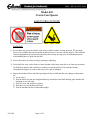
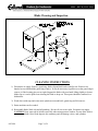
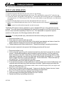
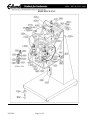
M098 – REV B (JULY 2006)
SERVICE MANUAL M098
MODEL # 610
CROWN OPENER
Page 1 of 8
8/4/2010
M098 – REV B (JULY 2006)
Model 610
Crown Can Opener
SAFETY PRECAUTIONS
WARNING!
1) Do not allow any person near knife or lid remover while machine is being operated. The fast, high
forces of air cylinders that operate the blade and lid remover can cause serious injuries. The two hand
controls and guards keep the operator away from these sharp, moving parts. Wear hand protection
when handling knives, open cans and lids.
2) Always disconnect air while cleaning, repairing or adjusting.
3) Check knife for wear, cracks, dents or bent teeth that could cause metal slivers or food trap areas that
are difficult to sanitize and could lead to sickness or internal injuries if can contents become
contaminated. Replace or return to the factory for repair if damaged.
4) Inspect the machine before and after operating each day or shift and after any change or adjustment
for:
1) Loose screws,
2) That the knock-out pins are straight and line up with holes in the blade backing plate and that the
mounting screws are tight,
3) That all covers and guards are in place,
4) That there isn’t any broken welds and,
5) That the machine has been cleaned thoroughly.
8/4/2010
Page 2 of 8
M098 – REV B (JULY 2006)
Blade Cleaning and Inspection
CLEANING INSTRUCTIONS
1) Disconnect air supply. Remove guard ring, blade clip and knife and wash after use. Remove two
knurled screws that hold the guard ring in place. It may be necessary to pull down on the guard ring to
remove it if the locating pins are too tight. Support the blade with your hand, lifting slightly to loosen
blade clip so it can be pulled out releasing the blade to drop out. These parts should be sanitized in a
dishwasher.
2) Wash down with soap and water entire splash area around knife, guard ring and lid remover.
3) Entire machine can be washed.
4) Reassemble blade, blade clip and all guarding. Be sure all screws are tight. Reconnect air supply
CAUTION! Keep water out of airlines especially when using pressure washers. Do not allow food to
remain on machine. Dried food deposits are unsanitary and can damage valves, and cylinders.
8/4/2010
Page 3 of 8
M098 – REV B (JULY 2006)
SETUP AND OPERATION
1) Unpack can opener and check for any loose screws or any damage.
2) Place can under the guard ring and against the locator. The can should be centered 3/16” under the ring.
3) Connect the airline. Air should be clean and dry (a 5 micron filter and coalescing filter are recommended).
Air requirement is 1-2 CFM at about 85 PSI. The valves and cylinders are pre lubricated, so no lubrication
is required.
4) Depress both palm buttons at the same time and hold until the lid is removed.
5) Remove can with both hands and remove the lid. Then the product can be dumped. Avoid sharp lid
edges.
6) Replace opened can with another unopened can and start again.
The Model 625 opener is factory adjusted to open a standard #10 can or the particular size can
ordered. The crown punch should penetrate the can just far enough to cut off the cover but not so
far as to cause excessive splashing of liquid in can. If an adjustment is required to improve
operation of the opener, the following procedure will be used:
CAUTION: To avoid personal injury, disconnect air line before making any adjustment.
1. Disconnect airline to unit.
2. Place can to be opened under can guard.
3. Loosen the four nuts or bolts at the rear of the vertical (see drawing) and raise or lower the
head as desired, keeping the can and can guard aligned and level.
4. Tighten fasteners and close interlock door. Operate according to operating instructions.
If a new size can is required to be opened, the following procedure will be used:
1. Disconnect airline to unit.
2. Hold up the knife guard ring with one hand and with the other hand unscrew the two thumb
screws. (A flathead screwdriver may be needed to start the screws.) Let the guard ring
down and place to the side. Now hold up on the knife with one hand (being careful of any
sharp parts of the knife), and with the other hand, pull the blade clip straight out. (You may
have to wiggle the knife to loosen the blade clip.) Let the knife down. Place knife and clip
with guard ring. Do not let knife fall in the deck.
3. Install desired crown punch and can guard onto opener.
4. If can knockout pin does not align with holes in crown punch loosen screws holding them and
rotate the pins until they line up with the holes in the knife. Tighten screws and mount the
knife, clip and guard ring. If lid remains in knife, make sure knockout pins (P016) are in place and
that knife is retracting all the way.
5. Place can to be opened under can guard. If new can is taller than former size can, loosen
the four nuts or bolts at rear of vertical (see drawing) and raise head.
6. Place 1/8 –3/16 inch thick shim between can and can guard.
7. Level and align head and tighten fasteners at rear of vertical.
8. Operate according to preceding instructions.
8/4/2010
Page 4 of 8
M098 – REV B (JULY 2006)
610 Operation and Troubleshooting
Operation Description
1. Place can in position against guard ring tab. There should be approximately 1/8" between the top of the
can and the bottom of the guard ring. Adjust, if necessary, keeping the head level and spaced evenly.
2. Connect a clean and dry air supply set to about 85-psi pressure.
3. Depress both green buttons at the same time and hold down until blade hits the end of stroke and release.
Lid should be completely separated from the can.
Pneumatic Description
The two green palm buttons (B138) are attached to one normally open (V005) and one normally closed 3-way
air valve (V002). The output of these two valves is connected to the pilot actuators of a 5-way valve (V015S).
The two outputs of the 5-way valve are connected to a 4" diameter air cylinder (C185), which is connected to
a blade (A756), which removes the lid. Both buttons must be actuated to shift the 5-way valve and extend the
cylinder and open the can. Releasing them shifts the 5-way valve back and retracts the air cylinder.
Troubleshooting
Only qualified maintenance personnel should do repairs.
Symptom
1. Unit will not operate when
buttons are pushed.
8/4/2010
a. Check air connection and supply pressure (air should
come out of unit when it is disconnected).
b. Remove cover to check valve operation. The valve
(V005) connected to the right button should only let
airflow through it when actuated. Remove the side hose
by pushing in collar and pulling out the hose at the same
time. Operating the button should let air out and
releasing it should stop it completely. The other button
and valve (V002) works just the opposite. If both
valves are OK then remove the upper hose to the
cylinder. Air should only come out of this hose when
both buttons are pushed. If no, (V015S) is faulty and
needs to be replaced. If it checks out OK, be sure
cylinder is not filled with water or oil and hydraulically
locked. With air disconnected and the hoses to the
cylinder disconnected, the cylinder should be free to be
pushed up and pulled down by hand. If it is seized up it
needs to be removed and replaced or repaired.
Page 5 of 8
M098 – REV B (JULY 2006)
Symptom
2. Air leaks out around
cylinder shaft near blade.
The cover must be removed to pinpoint leaks. Worn seals
usually cause cylinder end leaks and the cylinder must be
removed and repaired or replaced.
3. Air leaks out the 5-way
valve (V015S) exhaust.
The valve (V015S) probably needs repair or replacing.
Remove cylinder top hose to check if only the valve
(V015S) is faulty. If cylinder piston seals are bad, air will
come out of the top cylinder port.
4. Air leaks around one of the
valves, V002, V005 or
V015S.
Check to be sure all connections are tight and hoses are
pushed all the way on. If the three way valves are stuck or
worn out they can leak around the actuating stem.
Disassembly and cleaning is possible but replacement is
recommended.
5. Blade goes down, but will
not return.
a.
b.
c.
d.
6. Blade fails to open can
completely.
a. Inspect blade for damage – replace or return to the
factory for reconditioning.
b. To check cylinder stroke, hold both buttons down –
blade should come down at least 1-1/2" to the points or
3/8" to the valley. Cylinder may be loose, binding or
filled with water or oil and hydraulically locked, repair
or replace as necessary.
c. To adjust the head height – loosen bolts in back and
adjust head to correct height or slightly closer being sure
to keep the gap between guard ring and can even on
both sides.
d. If the lid is still attached near the front or back, check
the gap there, excessive variation before operation or
too much flexing during operation can be caused by a
bent frame or broken welds (be sure knife is good and
you have 85 psi of pressure). Return to factory for
repairs if frame is damaged.
7. Lid does not fall out of
knife.
a. Bent or broken knockout pin. Repair or replace.
b. Damaged blade holding the lid. Repair or replace.
8/4/2010
V002 valve stuck in and/or
V005 valve stuck in and/or
V015S valve stuck in open position and/or
Cylinder (C185) seized in down position. Repair or
replace factory parts.
Page 6 of 8
M098 – REV B (JULY 2006)
610 PARTS LIST
CO M P #
A6 00
A6 01
A6 031
A6 035
A7 20
A7 56J
A0 18
A0 19C
A0 60
B1 3 2
B136M
B1 3 7
B137B
B1 6 3
C0 8 4
C1 0 5
C1 2 4
C1 3 7
C1 8 5
F0 0 3
F0 0 9
F0 1 8
F0 3 6
F0 3 3
F0 3 7
F0 3 8
F0 5 0
F0 5 2
H027
H028
K0 3 9
K0 7 5
L2 1 1
L2 1 2
L2 1 3
M 080
N008
N039
P0 1 6
P0 2 8
P0 4 2
R0 4 6
S0 2 6
S0 3 3
S0 4 9
S0 6 8
S0 8 4
S3 4 9
S3 5 0
S5 0 4
V0 0 2
V0 0 5
V0 1 4
V0 1 5 S
W 010
W 013
W 021
W 024
8/4/2010
DESCRIPTION
W e l d m e n t , Fr am e (A 7 4 9 , F0 5 2 [4 ], R0 2 1 , R0 4 6 , S2 2 3 )
W e l d m e n t , Ram Pl at e (G0 2 8 [2 } , P0 4 2 [4 ], P1 0 3 )
A ssy , M i lle r Cy l W / M o u n t On ly
A ssy , A 6 0 3 1 Cy l. A ssy . W / Val v e (A lle n A i r Cy l. Re p l.)
A ssy , # 1 0 6 0 3 Gu ar d Ri n g (Sp e c i f y Ot h e r Can Si ze )
A ssy , # 1 0 Kn i f e (Sp e c i f y Ot h e r Can Si ze )
A d ap t o r , Pu sh Bu t t o n
A d ap t o r , Ram - Fo r Clip (A lle n A ir Cy l.)
A d ap t o r , Sw iv e l Elb o w 1 /4 N PT t o 1 /4 " ID H o se
Bu sh i n g , Re d u c t i o n 1 /4 t o 1 /8 " N PT
Bu sh i n g , Sn ap - M o d i f i e d
Bu t t o n , M u sh r o o m Pu sh
Bu t t o n , Bu t t o n On ly
Br ac k e t , # 6 1 0 Co v e r
Cli p ,# 1 0 Re t ain in g (Sp e c if i y Ot h e r Can Si ze )
Co u p li n g , A ir #3 8 2 2 4
Co v e r , Fr o n t
Co v e r , To p
Cy li n d e r , 4 " x 1 5 /8 " N FPA si d e m o u n t W / A d ap t e r
Fast e n e r , So u t h c o
Fi t t i n g , 1 /4 " N PT Br an c h
Fi t t i n g , Sw i v e l t o 1 /4 " ID H o se
Fi t t i n g , Pu sh -i n 1 /8 N PT t o 1 /4 OD H o se
Fi t t i n g , Pu sh -i n Sh o r t Elb o w 1 /8 N PT 1 /4 " OD
Fi t t i n g , Pu sh -i n Elb o w 1 /8 N PT t o 1 /4 " OD H o se
Fi t t i n g , Pu sh -i n Br an c h Te e 1 /8 N PT Br ass t o 1 /4 " OD
Fi t t i n g , Pu sh -i n Fit t in g Elb o w 1 /4 N PT t o 3 /8 " OD
Fo o t , # 6 1 0 /7 0 0
H o se , Cle ar 3 /8 " OD
H o se , Cle ar 1 /4 " OD
Kit , Ro d Bu sh i n g M i lle r
Kit , St ar y l 1 " Ro d b u sh i n g
Lab e l, W ar n in g " Kn i f e c u t H azar d "
Lab e l, W ar n in g " Ke e p Gu ar d s i n Plac e "
Lab e l, Cle an i n g In st r u c t i o n s
M o u n t , C1 8 5 Cy li n d e r
N i p p le , 2 " lo n g
N u t , A -4 1 4 1 -3 /4 -1 2
Pin , Kn o c k o u t
Pin , Ro ll
Pin , W e ld
Riv e t , SB 5 -6
Sc r e w , S/S 1 /2 - 1 3 x 1 " H e x
Sc r e w , S/S 1 /2 - 1 3 x 3 /4 " H e x
Sc r e w , S/S 1 0 - 3 2 x 3 /8 " H e x
Sc r e w , S/S 1 0 - 3 2 x 1 /4 " RH M
Sc r e w , 8 - 3 2 x 5 /1 6 " RH M
St an d o f f , C1 8 5 Cy li n d e r
Sc r e w , 1 /2 - 1 3 x 2 FH S
Sc r e w , S/S 4 m m x 1 0 F.H . Slo t t e d
Valv e , 3 -w ay N .O.
Valv e , 3 -w ay N .C.
Valv e , Old M ac 9 2 1 B-RA
Valv e , 5 -w ay SM C
W ash e r , S/S # 1 0 Flat
W ash e r , S/S 1 /2 Flat
W ash e r , S/S # 1 0 Lo c k
W ash e r , S/S 1 /2 Lo c k
Page 7 of 8
M098 – REV B (JULY 2006)
EDLUND CO. INC.
8/4/2010
Page 8 of 8