1
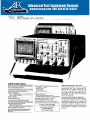
®
TEK
Advanced Test Equipment Rentals
100 MHz
FOUR CHANNEL OSCILLOSCOPES
www.atecorp.com 800-404-ATEC (2832)
E stablished 1981
∎
Tektronix
2M8
~
0,3f
.v
s
06 R
,Ki .
' : : wMlioil:q
µ'µyes,
4
o
: .rpen,W
~ iyingy
roo,
oirai
mV
-
IU4
3
°_
yotyaloty
j
x-a Savo,"
7
tea
r
#ix i∎ ~y ..`r.
ftx
s
i
cnrr p
rw,
C Y
xr
r
I
NEW 2246/2245
Bright, Crisp Display With High Writing Rate
Four Independent Channels
100 MHz Bandwidth With 2 ns/Div Time Base
On-Screen Scale Factor Readouts
Flexible Triggering
Auto Level and Auto HF, LF, Noise Reject,
TV Line and TV Field
Delayed Sweep
Control Status Lights
New Hands-Otf Voltmeter Measurements
+Peak and -Peak
Peak-to-Peak
Gated Peaks
Gated Peak-to-Peak
Dc
New SmartCursors"
Track Voltmeter Measurements
Visually Indicate Trigger Level and Ground
2% Vertical and Horizontal Accuracy
Time Measurements With Cursors or
Alternate Delayed Sweep Time
2 mV/Div Vertical Sensitivity at Full Bandwidth
Three Year Warranty-Five Year Option
New Specially Designed Probe
Improved, Rugged Tip
Hybrid Circuitry for Improved Performance
Simple, Rugged Construction
New Labeled Volts Cursors With GroundReferenced Readings and On-Screen
Readouts
TYPICAL APPLICATIONS
Logic Design and Repair
Communications
Power Supply Design
Higher Performance, Lower Price
The performance/price ratio for portable
oscilloscopes has been substantially upgraded . No other portable scope can otter
the range of productivity enhancing features and performance characteristics at a
comparably low price than the Tektronix
NEW 2245 and 2246.
Features That Promote Productivity
Four independent channels speed troubleshooting and design tasks by allowing
simultaneous observation of multiple test
points . Front panel set-ups are simplified by
pushbutton activated functions and onscreen scale factor readouts . And with buttons that light up, settings can be verified at
a glance.
STEK
2200
S ERIES
More Triggering Flexibility
Hands-free triggering, made possible by
the Auto-level mode, automatically places a
stable display of almost any waveform on
screen . The LF, HF, and Noise Reject
modes, together with a 10-to-1 holdoff
range, deliver stable triggering on complex
waveforms . The built-in TV Line and TV
Field triggering capability extends measurements to most video-related applications .
Performance Plus
The NEW 2245 and 2246 oscilloscopes
have low noise vertical systems that produce sharp, bright traces . Their 2 Ins time
base and 100 MHz bandwidth bring out the
details on high speed signals and render
measurements with good timing resolution .
Low level signal measurements are easily
managed by the 2 mV/div vertical sensitivity, even at full bandwidth, and by trigger
sensitivity that extends to 0 .25 div at
50 MHz (0,5 div at 100 MHz) .
Voltage Measurements With the Push
of a Button
A pushbutton activated measurement system on the 2246 enhances productivity even
more . This scope turns out virtually hands-off
measurements quickly of +peak, -peak,
peak-to-peak, dc, and gated volts, all with
convenient on-screen readout of values .
If more visual indication is desired, the unique
cursor system can provide feedback showing exactly where on the waveform an automatic measurement is being made . These
feedback cursors, when selected, even show
ground and trigger level locations.
There is also the ability to use cursors in
the conventional manual mode for making
point-to-point time and voltage measurements, including time interval measurements between a point on the reference
waveform and a point on any of four other
displayed waveforms .
Three Year Warranty
As with all of our high quality 2000 Series
Oscilloscopes, the 2245 and 2246 (including the CRT) are covered by the Tektronix
three year warranty, making ownership
more cost effective than ever .
CHARACTERISTICS
Characteristics are common to both instruments,
except where indicated .
VERTICAL SYSTEM
Display Modes - CH 1, CH 2, CH 3, CH 4, Add
(CH I+ CH 2), Invert (CH 2), Alternate and
Chopped display switching for all channels, and
20 MHz bandwidth limiting .
CHANNEL 1 AND CHANNEL 2
Frequency Response (-3dB Bandwidth) 100 MHz for temperatures from 0°C to +35°C .
90 MHz for temperatures from +35°C to +50°C .
100 MHz
FOUR CHANNEL OSCILLOSCOPES
Ac Coupled Lower -3dB Frequency - 10 Hz
or less with 1X probe . 1 Hz or less with standard
accessory 1OX probe .
Step Response - <3.5 ns for temperatures
from 0°C to +35°C . 'e3 .9 ns for temperatures
from +35°C to +50°C . Rise times calculated
from; t r =0 .35/BW.
Deflection Factor Range - 2 mV/div to 5 V/div
in a 1-2-5 sequence of 11 steps .
Maximum Error - ±2% for temperatures from
+15°C to +35°C . Add ± 1% for temperatures
from 0°C to +15°C and from +35°C to +50°C .
Variable Range - Continuously variable between VOLTS/DIV step settings . Increases step
setting by at least 2 .5 V/div .
Uncalibrated Indicators - A > symbol
appears on-screen when deflection factor is
between calibrated VOLTS/DIV step settings .
Channel Isolation - 50 dB or more attenuation
of deselected channel at 10 MHz . 34 dB or more
at 100 MHz . Measured with an eight div input signal and equal VOLTS/DIV settings on both channels from 2 mV/div to 0 .5 V/div.
Channel 2 Signal Delay With Respect to
Channel 1 -- <100 ps difference .
Input Characteristics - 1 MO ±0 .15% shunted by 20 pF ±0.5 pF . Maximum Input Voltage :
400 V (dc + peak ac) ; 800 V ac p-p at 10 kHz or
less .
Common Mode Rejection Ratio (ADD Mode
With Channel 2 Inverted) - At least 10 :1 at
50 MHz . For common-mode signals of eight div or
less and with VAR VOLTS/DIV control adjusted
for best CMRR at 50 kHz at any VOLTS/DIV
setting .
Trace Drift - Between VOLTS/DIV Step Settings : 0 .2 div or less . With VAR VOLTS/DIV Rotated Between Extremes : 1 div or less . Inverting
Channel 2 : 1 div or less . Between GND and Dc
Input Coupling : <0 .5 mV for temperatures from
0°C to +35°C . <2 mV for temperatures from
+35°C to +50°C.
Position Range - At least ± 11 div from graticule center .
CHANNEL 3 AND CHANNEL 4
Frequency Response - Same as Channel 1
and Channel 2 .
Step Response - Same as Channel I and
Channel 2 .
Deflection Factor - Settings : 0 .1 V/div and
0.5 V/div .
Maximum Error - Same as Channel 1 and
Channel 2.
Channel Isolation - 34 dB or more attenuation
of deselected channel at 100 MHz . Measured
with an eight div input signal .
Channel 4 Signal Delay With Respect to
Channel 3 - <100 ps difference .
Input Characteristics - 1 MO ±1% shunted
by 2 pF ± 0 .5 pF . Maximum Input Voltage : 400 V
(dc + peak ac) ; 800 V p-p ac at 10 kHz or less .
Trace Shift - Between VOLTS/DIV Settings : 1
div or less .
Position Range - Same as Channel 1 and
Channel 2 .
ALL CHANNELS
Low Frequency Linearity - 0 .06 div or less
compression or expansion of a 2 div, centerscreen signal when positioned anywhere within
the graticule area .
Bandwidth Limiter - Reduces upper -3dB
bandpass to a limit of 17 MHz to 23 MHz .
Trace Separation Range - t4 div .
Chop Mode Switching Rate - 625 kHz ± 10%,
Channel 3 or Channel 4 Signal Delay With
Respect to Either Channel I or Channel 2 <200 ps difference .
HORIZONTAL SYSTEM
Display Modes - A (main sweep), A ALTernate
with B (delayed sweep), and B. In X-Y mode,
Channel I provides X-axis (horizontal) deflection .
A Sweep Time Base Range -- 0 .5 s/div to
20 ns/div in a 1-2-5 sequence of 24 steps . X10
magnification extends fastest sweep rate to
2 ns/div .
B Sweep Time Base Range - 5 ms/div to
20 ns/div in a 1-2-5 sequence of 21 steps . X10
magnification extends fastest sweep rate to
2 ns/div.
Variable Timing Range -- Continuously variable between SEC/DIV calibrated step settings.
Extends slowest A sweep and B sweep speeds
by a factor of a least 2 .5 times . Affects the A
SEC/DIV setting with the A display mode ; affects
the B SEC/DIV setting with the ALT and B modes .
A Sweep Timing Accuracy - Applies over the
center eight div . Excludes the first 0 .25 div of the
magnified sweep and sweep beyond the 100th
magnified div .
Unmagnified
Magnified
+ 15°C to +35°C
t2%
t3%
0°c 10 +15°C
+35"C to +50°C
±3%
±4%
Range
Linearity - t 5% over any two of the center
eight div, or both unmagnified and magnified
displays .
Delay Time - Range : <0.1 div to >9 .9 div of
the A sweep . Maximum value does not exceed
end of the A sweep. Jitter : 1 :20,000 p-p (0.005%)
viewed over two seconds .
ATime - (2246) Range : 0 to >10 div to right of
the delay time setting, but does not exceed end
of the A sweep . Accuracy : t (O .5% of reading
+1% of one A sweep div +20 ns).
TRIGGERING
Trigger Sensitivity from CH 1, CH 2, CH 3, CH 2
Source .
Dc Coupled-- • 0.35 div or greater triggers from
do to 50 MHz, increasing to 1 div at 150 MHz.
Noise Reject Coupled -- 0 .8 div or more triggers ; 0.5 div or less does not trigger .
HF Reject Coupled - 0 .35 div or greater triggers from do to 50 kHz ; 0 .25 div or less does not
trigger above 500 kHz .
LF Reject Coupled - 0 .35 div or greater triggers from 100 kHz to 50 MHz ; 0 .35 div or greater
does not trigger from dc to 10 kHz .
Ac Coupled - 0 .35 div or greater triggers from
50 Hz and 50 MHz ; 0 .35 div or less does not trigger from dc to 5 Hz .
For do, LF Reject, and ac coupling above 50 MHz,
triggering signal requirement increases to 1 .0 div
at 150 MHz .
2200
SERIES
100 MHz
FOUR CHANNEL OSCILLOSCOPES
TEK
Trigger Sensitivity From TV Line or TV Field
Source - 0 .5 div or less of composite sync
achieves stable display .
Lowest Usable Frequency With Auto Level
Function - 10 Hz .
Level Control Range - f 20 div referenced to
the selected source .
Level Readout Accuracy - ±(0 .3% of reading +0.1 div) .
Variable Holdoff Range - Increases the
A sweep holdoff time by at least a factor of 10 .
X-Y OPERATION
Deflection Factors - Same as Vertical System,
with VAR VOLTS/DIV in calibrated decent.
Maximum Error
Y°Axis
X-Axis
+15°C to +35'C
Range
t2%
t3%
0°C to +15°C
+35°C 10 +50
±3%
s4%
C
Ambient Temperature - Operating : 0°C to
+50°C . Nonoperating : -50°C to -75°C.
Altitude - Operating : To 4500 m (15,000 ft) .
Maximum operating temperature decreases I 'C
for each 300 (1,000 ft) above 1500 m (5000 ft) .
Nonoperating : to 15 250 m (50,000 ft) .
Vibration - Operating : 15 minutes along each
of three axes, 0 .015 inch p-p displacement. 10 Hz
to 55 Hz in one minute sweeps . Held for 10 minutes at 55 Hz (2.4 g's at 55 Hz) .
Humidity - Operating and Nonoperating : 95%,
five cycles (120 hours) referenced to
MIL-T-288000, Paragraph 4 .5 .5 .1 .2 .2 for Type III,
Class 5 .
Shock -- Operating and Nonoperating : 30 g,
half sine, 11 ms duration ; three shocks on each
face, for a total of 18 shocks.
Bench Handling Test - 4 inch drop per Tektronix Standard 062-2858.00.
Transportation Drop and Vibration -- Meets
the limits of Tektronix Standard 062-2858-00 .
X-Axis -3dB Bandwidth - 3 MHz or more .
Phase Difference Between X and Y - s3°
for dc coupled signals from do to 50 kHz with
bandwidth limiter off.
CURSOR AND FRONT PANEL DISPLAY
Controls - Separate A Intensity, B Intensity,
Readout Intensity, Focus, Beam Finder, Trace Rotation, and Scale Illumination .
CRT - 8 x 10 cm internal graticule . Markings :
8 major div vertically and 10 major div horizontally,
with auxiliary markings .
Standard Phosphor - GH (P31) .
Y-Axis Orthogonality - <01 div over eight
vertical div ; no adjustment.
Cursor Functions-(2246)
Function
Accuracy
SEC; 1/SEC, PHASE,
ATIME; A 1/TIME : APHASE
±(0 .5% of reading +
0.02 horizontal dv)
VOLTS; GND VOLTS
±10.5% of reading + 0.02 vertical
div + HF display errors)
Function
Track Measurement,
Trig Level, Ground
Position Accuracy °+
±005 vertical div
Cursor position on waveform vs readout displayed value .
EXTERNAL Z-AXIS INPUT
Active Region Lower Threshold - ' 1 .8 V.
Signal Required to Blank Sweep-Related
Trace - X3.8 V .
Input Resistance to Ground - 10 kfi ± 10% .
Maximum Input Voltage - 30 V (do + peak
ac) or _-30 V ac p-p at I kHz.
CALIBRATOR OUTPUT
Voltage Into I MO Load - 0 .5 V ±2%.
Repetition Range - t kHz ± 10% .
Overshoot - <0 .1% .
POWER REQUIREMENTS
Line Voltage Range - 90 V to 250 V .
Line Frequency - 48 Hz to 445 Hz .
Fuse Rating - 2 A, 250 V, slow-blow .
Maximum Power Consumption -- 80 W (110
V ac).
ENVIRONMENTAL
Environmental requirements quality the electrical
and mechanical specifications . When not rackmounted, the instrument meets the environmental
requirements of MILT-288000 for Type III, Class
5, Style D equipment .
PHYSICAL CHARACTERISTICS
Dimensions
In
Width, With handle
Height
With feel and pouch
Without pouch
Depth
With front cover
With handle extended
361
14 .2
177
164
7,0
64
445
5 9
17 .5
20 .4
weight-
kg
Net
With accessories and pouch
Without accessories and pouch
e9
79
I
196
17 .4
WARRANTY-PLUS SERVICE PLANS
SEE PAGE 497
M1 - (2245) 2 Calibrations .
M1 - (2246) 2 Calibrations,
M2 - (2245) 2 Years Service.
M2 - (2246) 2 Years Service.
M3 - (2245) 2 Years Service and 4 Calibrations.
M3 - (2246) 2 Years Service and 4 Calibrations.
M4 - (2245) 5 Calibrations .
M4 - (2246) 5 Calibrations .
M5 - (2245) 9 Calibrations + 2 Years Service .
MS - (2246) 9 Calibrations + 2 Years Service .
+$145
+$160
+$175
+$185
+$290
+$320
+$385
+$410
+$1,005
+$1,095
OPTIONAL ACCESSORIES
Service Manual
(2245/2246) Order 070-6081-00
$25
Front Panel Cover - Order 200-3232-00
$5.00
Accessory Pouch - Order 016-0857 .00
$15
Accessory Pouch and Covers
Protective Waterproof Vinyl Cover Order 016-0848.00
$15
Viewing Hoods (Collapsible) Order 016-0592-00
$14
(Binocular) Order 016-0566-00
$18 .75
(Polarized) Order 016-018000
$50
Clear Implosion Shield- Order 337-2775-01 . +$1 .95
Carrying Strap - Order 346-0199-00
$17
Carrying Case - Order 016-0792-01"
$355
Clear Graticule Filter - Order 337-2775-01
$1 .96
1107 Mounting Kit - Order 016-0785-00
$50
1107 DC Inverter --- See page 307 .
$525
1106 Battery Pack - See page 306.
$1,265
$1,690
1105 Power Supply - See page 306 .
'' Recommend use with front panel cover (200-2520-00).
'a To order, contact your local Tektronix Sales Of floe.
2246
RECOMMENDED PROBES
See Probe Section for additional probes, page 464 .
With Voltmeter
Dc Volts - Accuracy : ±(0 .3% of reading +0 .02
div). Normal Mode Rejection Ratio : >50 dB at
50 Hz and 60 Hz .
+Peak and -Peak Volts -- Accuracy : ± (2%
of reading +0.1 div) for signals from 20 Hz to
30 MHz . -3dB at 100 MHz . Gated Region Minimum Width : --(0 .2 div + 50 ns) .
P-P Volts - Accuracy : ± (2% of reading
+0 .1 div) for signals from 20 Hz to 30 MHz .
-3 dB from 30 MHz to 100 MHz . Gated Region
Minimum Width : --(0 .2 div + 50 ns) .
ORDERING INFORMATION
2245 100 MHz Oscilloscope $1,875
Includes: Two 10X, 1 .5 m probes with accessories
(P6109 Opt 01); clear accessories pouch with ziploc fastener (016-0537. 00) ; blue plastic CRT filter (337-2775-00) ;
2A, 250 V fuse (159-0023-00) ; operator manual
(070-6083-00); user reference guide (070-6082-00) .
2246 100 MHz Oscilloscope with Voltmeter, Time, and SmartCursors $2,400
Includes: Same as 2245 .
OPTIONS
Option 02 - Protective front panel cover and
accessory pouch,
Option 1C - C-SC Option 02 Camera .
Option 1 K - K212 Portable Instrument Cart .
Option 1T - Transit Case .
Option 22 - Two additional P6109 probes .
Option 23 - Two 1X/10X P6062B, 6 ft probes.
+$47
+$465
+$330
+$185
+$130
+$350
INTERNATIONAL POWER PLUG OPTIONS
Option A1 - Universal Euro 220 V, 50 Hz .
Option
Option
Option
Option
A2
A3
A4
AS
- UK 240 V, 50 Hz .
- Australian 240 V, 50 Hz .
- North American 240 V, 60 Hz .
- Switzerland 220 V, 50 Hz .
The P6062B allows switching between 1X and 10X attenuation. Readout display changes with attenuation
switching . See page 470 .
P6109 - 10 X Probe .
$58
P6062B - 1X-10X Probe .
$175
P6008 - Environmental Probe.
$240
P6009 - High Voltage Probe .
$195
P6202A - Active Probe.
$680
$425
1101A - Active Probe Power Supply .
A6302 - Current Probe .
$565
A6303 - Current Probe .
$1,070
AM 503 --- Current Probe Amplifier .
$1,126
A6901 Ground isolation Monitor See page 478 . Order A6901
$650
A6902B Isolator - See page 479 .
$1,795
RECOMMENDED CAMERAS
C-5C Option 02 - See page 445 .
C-7 Option 03 - See page 448.
C-4 - See page 446 .
$465
$565
$370
RECOMMENDED CART
K212 - For on-site mobility. See page 461 .
$330