1
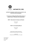
F-53:F-53
1/29/10
10:04 AM
Page 1
Bulletin F-53
Series 700 Sight Flow Indicators
Specifications - Installation and Operating Instructions
Sizes
Inches
1/4 & 3/8
1/2 & 3/4
1, 1-1/4
& 1-1/2
NOTE: Read safety precautions on back before installing
or operating!
INSTALLATION
1. Use proper sealing compound on the fitting threads.
2. Check the flow direction arrow on hex to make sure the
sight flow indicator is aligned properly.
3. Attach sight flow indicator to the correct size fittings.
4. Hold the sight flow indicator in place with the correct
size wrench by the hex adjacent to the fitting.
5. Avoid over tightening the fittings or placing stress on
the sight flow indicator.
6. Attach the other side of the sight flow indicator
repeating steps 1-5 above making sure a torque load is
NOT applied across the unit.
OPERATION
1. Gradually introduce the medium into the sight flow
indicator. Avoid any pressure surges.
2. The rotation of the impeller indicates flow. See table
right for minimum flow surges.
2. The rotation of the impeller indicated flow. See table
right for minimum flow values.
3. By rotating the glass axially, the wipers will clean the
inner surface of the glass. Care should be taken while
medium is flowing.
W.E. ANDERSON DIV., DWYER INSTRUMENTS, INC.
P.O. BOX 358 • MICHIGAN CITY, INDIANA 46361 U.S.A.
Dim “L”
Inches (mm)
2-3/4 (70)
3-11/16 (94)
4-7/8 (124)
Dim “H”
Inches (mm)
1-1/2 (38)
2-1/4 (57)
2-3/4 (70)
SPECIFICATIONS
Wetted Materials:
Body: Model 700; nickel plated brass.
Model 700 SS; 316 Stainless.
Window: Tempered boroslicate glass.
O-ring: Florelastomer.
Wiper: Florelastomer.
Spindle: 416 Stainless Steel.
Impeller: Acetal plastic.
Temperature Limit: 212ºF (100ºC).
Pressure Limit: 230 psig (1585.8 kPa).
Weight: 1 to 5 lb. (.45 to 2.3 kg) Depending on model.
Options: BSPP or BSPT metric thread forms, less
impeller, bidirectional flow models.
Minimum Flows for Impeller
Rotation (nominal)
Size
Inches
1/4
3/8
1/2
3/4
1
1-1/4
1-1/2
Water
GPM (LPM)
0.10 (0.38)
0.10 (0.38)
0.25 (0.95)
0.30 (1.14)
0.50 (1.89)
0.80 (3.03)
1.0 (3.79)
Phone: 219/879-8000
Fax: 219/872-9057
Air
SCFM (LPM)
1.1 (31.2)
1.1 (31.2)
2.0 (56.6)
2.0 (56.6)
4.0 (113.3)
5.0 (141.6)
5.0 (141.6)
www.dwyer-inst.com
e-mail: [email protected]
F-53:F-53
1/29/10
10:04 AM
Page 2
You have purchased a quality Sight Flow Indicator. Please protect your safety and that of others by observing
the following safety instructions when installing and operating your new Sight Flow Indicator.
Your Safety and Others Depend on Proper Installation
and Operation
Never install a sight flow indicator unit in an unsupported
position.
• Make sure that the lines connected to both sides of
the unit do NOT put undue stress on the unit at any
time.
• Check alignment of lines on both sides of the unit to
prevent torque from being applied to the unit when
installed.
• Always consider the weight of the unit, fluid lines, and
the medium when calculating stresses.
Always inspect sight flow indicator units for fractures,
cracks or other defects before installation. If unit is found
with any defect, do NOT install. Consult factory. The
defective products performance and safety cannot be
guaranteed.
In no instance are the temperature and pressure limits
specified on the instrument to be exceeded. This includes
the following circumstances:
• “Water Hammer”
The sudden surge that occurs when a downstream
flow is suddenly stopped (i.e. shutting a valve). This
causes the water in the line upstream to slam into the
wall stopping flow (i.e. valve) sometimes causing
severe damage to the sight floe indicator. Damage is
due to the water mass momentum causing a large
pressure increase.
• “Fluid Surges”
Empty fluid lines pressurized suddenly (i.e. by a pump
or the rapid opening of a supply valve) can cause a
large fluid surge with no back pressure. These
conditions are similar to “water hammer”.
• “Thermal Liquid Expansion/Contraction”
This may be due to water freezing in the unit or a
liquid thermally expanding in an isolated unit. Both
cases can be avoided by draining units when not in
use.
Use care when installing the sight flow unit to fittings.
• Always hold unit with wrench at hex adjacent to
connection when installing.
• Do NOT apply torque loads across the unit.
• Do NOT overtighten fittings.
• Use proper sealing techniques (i.e. pipe thread
sealant tape, joint compound) to ease tightening of
fittings and ensure proper seal.
• Do NOT hold unit by housing or glass when installing.
Always, use the hex fitting provided.
• Avoid causing any damage to the glass surface when
installing the unit. Even slight damaging the surface of
the glass may greatly reduce the glass’ strength.
These units are designed to use specific mediums (i.e.
water, air, and oil). For use with other mediums, consult
Dwyer Instruments, Inc.’s Sales Department.
Limited Warranty: The Seller warrants all Dwyer instruments and equipment to be free from defects in workmanship or material under normal use and service for a period
of one year from date of shipment. Liability under this warranty is limited to repair or replacement F.O.B. factory of any parts which prove to be defective within that time or
repayment of the purchase price at the Seller’s option provided the instruments have been returned, transportation prepaid, within one year from the date of purchase. All
technical advice, recommendations and services are based on technical data and information which the Seller believes to be reliable and are intended for use by persons having skill and knowledge of the business, at their own discretion. In no case is Seller liable beyond replacement of equipment F.O.B. factory or the full purchase price. This
warranty does not apply if the maximum ratings label is removed or if the instrument or equipment is abused, altered, used at ratings above the maximum specified, or otherwise misused in any way.
THIS EXPRESS LIMITED WARRANTY IS IN LIEU OF AND EXCLUDES ALL OTHER REPRESENTATIONS MADE BY ADVERTISEMENTS OR BY AGENTS AND ALL
OTHER WARRANTIES, BOTH EXPRESS AND IMPLIED. THERE ARE NO IMPLIED WARRANTIES OF MERCHANTABILITY OR OF FITNESS FOR A PARTICULAR PURPOSE FOR GOODS COVERED HEREUNDER.
Buyers Remedies: THE BUYER’S EXCLUSIVE AND SOLE REMEDY ON ACCOUNT OF OR IN RESPECT TO THE FURNISHING OF NON-CONFORMING OR DEFECTIVE MATERIAL SHALL BE TO SECURE REPLACEMENT THEREOF AS AFORESAID. THE SELLER SHALL NOT IN ANY EVENT BE LIABLE FOR THE COST OF ANY
LABOR EXPENDED ON ANY SUCH MATERIAL OR FORM ANY SPECIAL, DIRECT, INDIRECT OR CONSEQUENTIAL DAMAGES TO ANYONE BY REASON OF THE
FACT THAT IT SHALL HAVE BEEN NON-CONFORMING OR DEFECTIVE.
©Copyright 2010 Dwyer Instruments, Inc.
Printed in U.S.A. 2/10
W.E. ANDERSON DIV., DWYER INSTRUMENTS, INC.
P.O. BOX 358 • MICHIGAN CITY, INDIANA 46361 U.S.A.
Phone: 219/879-8000
Fax: 219/872-9057
FR# 83-440787-00 Rev. 2
www.dwyer-inst.com
e-mail: [email protected]