1
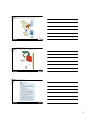
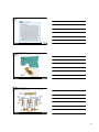
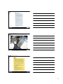
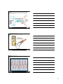
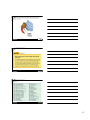
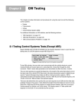
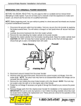
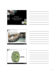
107
ABS DIAGNOSIS AND
SERVICE
Automotive Technology, Fifth Edition
James Halderman
© 2011 Pearson Education, Inc.!
All Rights Reserved!
107 ABS DIAGNOSIS AND SERVICE
Figure 107-1 On most vehicles equipped with ABS, the amber ABS and red BRAKE warning lamp
should come on as a bulb check when the ignition is first switched on.
Automotive Technology, Fifth Edition
James Halderman
© 2011 Pearson Education, Inc.!
All Rights Reserved!
107 ABS DIAGNOSIS AND SERVICE
Figure 107-2 A thorough visual inspection should include carefully inspecting around the
electrohydraulic unit for signs of obvious problems or the installation of aftermarket devices such as
alarm systems.
Automotive Technology, Fifth Edition
James Halderman
© 2011 Pearson Education, Inc.!
All Rights Reserved!
1
107 ABS DIAGNOSIS AND SERVICE
TECH TIP: Quick and Easy Wheel Speed Sensor
Diagnosis A fault in a wheel speed sensor (WSS)
is a common ABS problem. A quick and easy test that
works on most Bosch ABS systems (and perhaps
others) involves the following steps:
STEP 1 Hoist the vehicle safely.
STEP 2 Turn the ignition on (engine off).
STEP 3 Spin a tire by hand as fast as possible.
STEP 4 The ABS amber warning light should come on,
indicating that a speed was detected but not by all
the wheel speed sensors.
STEP 5 Turn the ignition off to reset the ABS warning
light.
STEP 6 Repeat the test on each of the remaining
wheels.
If any wheel fails to turn on the ABS light, carefully
inspect the wheel speed sensor for proper resistance
and the tone ring and wiring. If the ABS light is on all
the time and does not reset when the ignition is
turned off, the problem is not caused by a wheel
speed sensor.
Automotive Technology, Fifth Edition
James Halderman
© 2011 Pearson Education, Inc.!
All Rights Reserved!
107 ABS DIAGNOSIS AND SERVICE
FREQUENTLY ASKED QUESTION: What s That
Noise and Vibration? Many vehicle owners and
service technicians have been disturbed to hear and
feel an occasional groaning noise. It is usually heard
and felt through the vehicle after first being started
and driven. Because it occurs when first being driven
in forward or reverse, many technicians have blamed
the transmission or related driveline components.
This is commonly heard on many ABS vehicles as part
of a system check. As soon as the ABS controller
senses speed from the wheel speed sensors after an
ignition cycles on, the controller will run the pump
either every time or whenever the accumulator
pressure is below a certain level. This can occur while
the vehicle is being backed out of a driveway or being
driven forward because wheel sensors can only detect
speed—not direction. Before serious and major
repairs are attempted to cure a noise, make sure
that it is not the normal ABS self-test activation
sequence of events.
Automotive Technology, Fifth Edition
James Halderman
© 2011 Pearson Education, Inc.!
All Rights Reserved!
107 ABS DIAGNOSIS AND SERVICE
Figure 107-3 General Motors diagnostic connector on a pre- 1996 vehicle. Flash codes are
available by using a jumper wire to ground (terminal A) to terminal H.
Automotive Technology, Fifth Edition
James Halderman
© 2011 Pearson Education, Inc.!
All Rights Reserved!
2
107 ABS DIAGNOSIS AND SERVICE
Figure 107-4 Connecting a jumper wire from the diagnostic connector to ground. The exact
location of this diagnostic connector varies with the exact vehicle model and year.
Automotive Technology, Fifth Edition
James Halderman
© 2011 Pearson Education, Inc.!
All Rights Reserved!
107 ABS DIAGNOSIS AND SERVICE
Figure 107-5
Chrysler diagnostic connector location varies with the model and year.
Automotive Technology, Fifth Edition
James Halderman
© 2011 Pearson Education, Inc.!
All Rights Reserved!
107 ABS DIAGNOSIS AND SERVICE
REAL WORLD FIX: RWAL Diagnosis The owner of an
S-10 pickup truck complained that the red brake warning lamp
on the dash remained on even when the parking brake was
released. The problem could be one of the following:
1. A serious hydraulic problem
2. Low brake fluid
3. A stuck or defective parking brake switch
4. If the brake lamp is dim, RWAL trouble is indicated.
The technician found that the brake lamp was on dimly,
indicating that an antilock braking problem was detected. The
first step in diagnosing an antilock braking problem with a
dash lamp on is to check for stored trouble codes. The
technician used a jumper between terminals A and H on the
DLC (ALCL), and four flashes of the brake lamp indicated a
code 4.
Checking a service manual, code 4 was found to be a
grounded switch inside the hydraulic control unit. The hardest
part about the repair was getting access to, and the
replacement of, the defective (electrically grounded) switch.
After bleeding the system and a thorough test drive, the lamp
sequence and RWAL functioned correctly.
Automotive Technology, Fifth Edition
James Halderman
© 2011 Pearson Education, Inc.!
All Rights Reserved!
3
107 ABS DIAGNOSIS AND SERVICE
REAL WORLD FIX: The Nervous Taurus A
customer complained that, sometimes during
normal braking, the ABS would be activated
just before coming to a stop. However, the
ABS light would not come on. The service
technician was able to duplicate the condition
and there were no DTCs stored. Using a scan
tool to monitor the wheel speed sensors, the
technician discovered that the left front wheel
speed was slightly different than the others. A
thorough visual inspection revealed that the
tone wheel (sensor ring) was cracked. This
crack created a different wheel speed signal to
the ABS controller than the other wheels and
the controller activated the ABS as it would
normally—that was why there were no DTCs.
Other things that could have caused this
problem, which is often called false
modulation, include a bent wheel,
mismatched tire sizes, or metal debris around
the sensor.
Automotive Technology, Fifth Edition
James Halderman
© 2011 Pearson Education, Inc.!
All Rights Reserved!
107 ABS DIAGNOSIS AND SERVICE
Figure 107-6 A scan tool is the recommended method to use to access General Motors Teves
Mark IV systems.
Automotive Technology, Fifth Edition
James Halderman
© 2011 Pearson Education, Inc.!
All Rights Reserved!
107 ABS DIAGNOSIS AND SERVICE
Figure 107-7 The Delphi (Delco) VI attaches to the side of the master cylinder and connects
hydraulically through transfer tube assemblies.
Automotive Technology, Fifth Edition
James Halderman
© 2011 Pearson Education, Inc.!
All Rights Reserved!
4
107 ABS DIAGNOSIS AND SERVICE
REAL WORLD FIX: The Mystery ABS
Amber Warning Light The owner of an
Acura Legend complained to a service
technician that the ABS warning light would
come on but only while driving down from a
parking garage. When the driver turned off the
ignition and restarted the engine, the ABS
amber light was not on and did not come on
again until the vehicle was again driven down
the spiral parking garage ramp. The service
technician used a scan tool and found that no
DTCs had been stored.
NOTE: Some ABS systems will not retain a DTC
unless the problem is currently present and
the ABS amber warning light is on.
All of the brakes were in excellent condition,
but the brake fluid level was down a little.
After topping off the master cylinder with clean
DOT 3 brake fluid, the vehicle was returned to
the customer with the following information:
• The ABS amber warning light may have been
triggered by the brake fluid level switch. While
driving down the steep parking garage ramp,
the brake fluid moved away from the fluid level
sensor.
NOTE: While the brake fluid level sensor
normally would turn on the red brake warning
light, in some systems it turns on the amber
ABS light if the brake fluid falls below a certain
level in the ABS reservoir.
• The difference in wheel speed between the
outboard and the inboard wheels could have
triggered a fault code for a wheel speed sensor
during the drive down the spiral parking
garage ramp.
Automotive Technology, Fifth Edition
James Halderman
© 2011 Pearson Education, Inc.!
All Rights Reserved!
107 ABS DIAGNOSIS AND SERVICE
Figure 107-8 A breakout box is being used to diagnose an ABS problem. The controller
(computer) is located in the trunk of this vehicle, and a digital multimeter is being used to measure
resistance and voltage at various points in the system, following the service manual procedure.
Automotive Technology, Fifth Edition
James Halderman
© 2011 Pearson Education, Inc.!
All Rights Reserved!
107 ABS DIAGNOSIS AND SERVICE
TECH TIP: Sometimes It Pays to Look at
the Entire Vehicle There are often strange
electrical problems that can occur including
false DTCs or intermittent operation of
electrical sensors, ABS, accessories, or gauges.
Sometimes the root of these problems is due
to rust and corrosion after a vehicle is involved
in a flood. Here are some telltale signs that a
vehicle may have been in a flood or in deep
water.
• Mud, silt, or caked dust under the dash and
inside the doors
• Corroded electrical connectors at the
computer, fuse box, or ABS controller
(computer)
• Visible water line in the doors or behind
panels
• Rust in abnormal places such as seat springs
or brackets behind the dash
• Moisture in lenses
• Musty smell and/or strong air freshener smell
• Powdery corrosion on aluminum parts such
as intake manifold and inside the throttle bore
• Rust or moisture inside electrical switches or
relays
• Areas that are normally dusty such as an
ashtray or glove box are very clean
Automotive Technology, Fifth Edition
James Halderman
© 2011 Pearson Education, Inc.!
All Rights Reserved!
5
107 ABS DIAGNOSIS AND SERVICE
Figure 107-9 Typical wheel speed sensor. When a tooth on the sensor ring is close to the sensor, the
strength of the magnetic field is stronger because the metal of the tooth conducts magnetic lines of force
better than air. When the tooth moves away, the magnetic field strength is reduced. It is this changing
magnetic field strength that produces the changing voltage. Frequency of the signal is determined by the
speed of the rotating sensor.
Automotive Technology, Fifth Edition
James Halderman
© 2011 Pearson Education, Inc.!
All Rights Reserved!
107 ABS DIAGNOSIS AND SERVICE
Figure 107-10
Measuring the resistance of a wheel speed sensor.
Automotive Technology, Fifth Edition
James Halderman
© 2011 Pearson Education, Inc.!
All Rights Reserved!
107 ABS DIAGNOSIS AND SERVICE
Figure 107-11
A scope can be used to check for proper operation of a wheel speed sensor.
Automotive Technology, Fifth Edition
James Halderman
© 2011 Pearson Education, Inc.!
All Rights Reserved!
6
107 ABS DIAGNOSIS AND SERVICE
Figure 107-12
missing wave.
A broken tooth on a wheel speed sensor tone ring shows on the scope trace as a
Automotive Technology, Fifth Edition
James Halderman
© 2011 Pearson Education, Inc.!
All Rights Reserved!
107 ABS DIAGNOSIS AND SERVICE
Figure 107-13 Use a nonmagnetic brass or plastic feeler gauge to check wheel speed sensor gap.
A steel gauge would be attracted by the magnet in the sensor and would produce a drag on the
gauge as it is moved between the sensor and the tone ring. This drag could be interpreted as a
correct clearance reading.
Automotive Technology, Fifth Edition
James Halderman
© 2011 Pearson Education, Inc.!
All Rights Reserved!
107 ABS DIAGNOSIS AND SERVICE
Figure 107-14 (a) Always use a nonferrous (brass or plastic) feeler (thickness) gauge when
measuring the gap between the toothed ring and the wheel speed sensor.
Automotive Technology, Fifth Edition
James Halderman
© 2011 Pearson Education, Inc.!
All Rights Reserved!
7
107 ABS DIAGNOSIS AND SERVICE
Figure 107-14 (b) Sometimes a sensor is equipped with a paper spacer that is the exact
thickness of the spacing required between the toothed ring and the sensor. If equipped, the sensor is
simply installed with the paper touching the toothed wheel. A typical gap ranges from 0.020 to
0.050 in. (0.5 to 1.3 mm).
Automotive Technology, Fifth Edition
James Halderman
© 2011 Pearson Education, Inc.!
All Rights Reserved!
107 ABS DIAGNOSIS AND SERVICE
TECH TIP: Space Saver
Spare Tire May Trigger
Wheel Speed Fault Code If
a vehicle has been using a
small space saver-type spare
tire, then the difference in
outside diameter may trigger a
wheel speed sensor diagnostic
trouble code (DTC) and turn on
the amber ABS warning lamp.
Try to find out from the
customer if they had driven on
a spare tire before replacing a
wheel speed sensor based on a
stored DTC.
Automotive Technology, Fifth Edition
James Halderman
© 2011 Pearson Education, Inc.!
All Rights Reserved!
107 ABS DIAGNOSIS AND SERVICE
CHART 107–1
Automotive Technology, Fifth Edition
James Halderman
© 2011 Pearson Education, Inc.!
All Rights Reserved!
8
107 ABS DIAGNOSIS AND SERVICE
CHART 107–1 (continued)
Automotive Technology, Fifth Edition
James Halderman
© 2011 Pearson Education, Inc.!
All Rights Reserved!
107 ABS DIAGNOSIS AND SERVICE
CHART 107–1 (continued)
Automotive Technology, Fifth Edition
James Halderman
© 2011 Pearson Education, Inc.!
All Rights Reserved!
9