1
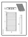
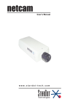
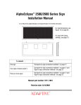
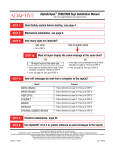
X-BOARD100/200
& X-Soft User's Guide
X-100/200 Instruction Manual
X-100/200 Troubleshooting
X-100/200 Service Manual
X-Soft Software User's Guide
About DMX Trigger Converter(DTC-512)
About X-Board-Controller
Web site: www.ncw.com.hk
E-mail: [email protected]
Part Number:24-004-1642
Instruction version:1.2
Welcome!
Thank you for your purchase of this product. Every product has been thoroughly tested
and carefully packed before delivery. Unpack the shipping carton carefully, saving the
carton and all packaging materials for possible later use. Check carefully for sure your
product is not damaged and all accessories not missing. If your product appears to be
damaged or missing, please do not use it and contact your authorized dealer immediately.
What is X-Board 100/200?
Neither a spotlight, nor a moving light, based on the latest LED technology, X-Board 100/200
is the affordable transparent LED multimedia demonstration screen. Because of the luminous
light, the transparency and lightweight qualities, the X-Board 100/200 is ideal for stage
performances, music concert, fashion show, theater, stadium and other special occasions.
X-Board 100/200 is an X. X. L (extra extra large) display screen where light and video
converge. Facing a screen with an area of approximate 100/200 sq m and viewing from a
distance of 20m or more, you will enjoy a visual shock beyond your imagination.
The still images, animation picture, video and texts being integrated, X-Board 100/200
sets a new standard in the area of communication medium and sets off an interactive,
terrific experience you'll have yet to adapt to.
With today's plethora of visual message, there is an increasing need for eye-catcher,
undoubtedly, X-Board 100/200 is just the answer.
Technical Specifications
Weight:
Overall Dimensions:
Power Supply:
Power Consumption:
Lighting Source:
Luminous Intensity:
Pixel Density:
Distance of Pixel:
Image Size:
Frame rate:
Transparency:
Trigger Signal:
DMX Assignment:
Picture Memory Space:
IP Rating:
38kg
1960x960x180mm
AC 230V~50/60Hz or AC 120V~50/60Hz
100 Watt/ sqm
512 RGB LED modules
500 cd/sqm
1,900 cd
60 mm
32x16 pixels
50 fps (frame per second)
50%
USITT DMX-512(1990)
20 channels
2 scenes of pictures, up to 70 pictures each
IP 66
1
The X-Board 100/200 & Accessories
4 M10 x25 three-cornered bakelite screws for coupling adjustment
14 AWG 3-core Power cable with two Neutrik Powercon male sockets, 0.8 meter
IEEE 1284 data cable with 36-way CN36 M/ CN 36 M sockets
3 carrying handles on either side, total 6 for ease movement
2 cylindric(diameter 30mm) connection adaptors with threads M10 and 2xM8 to
reinforce safety mounting
2 M12 stainless steel turnbuckles with hook, together with M12 threaded rod and
hanging ring
User manual
X-Soft setup program CD
Carrying handle, total 6pcs,
(no assembly required)
M10 three-cornered
bakelite screw,
total 4pcs
Turnbuckle with hook,
threaded rod and
hanging ring
(no assembly required)
IEEE 1284 data cable
2
Connection adaptor, total 2pcs
(no assembly required)
Power cable with two
Neutrik Powercon sockets
Project Setup
Precautions during setup
Use specified DVI Graphic Card
This system requires using ATI 9200/9500/9700/9800 AGP DVI 64MB or more Graphic
card. It won't work if you use the graphic card other than the one we specify. Please
remember you'll have to uninstall the old graphic card and then install the new DVI
graphic card.
out
out
in
Right
Left
Input and output can not be inverted
Standing in the front(facing the X-Board 100/200), we can tell the input connectors are on
the right while the output connectors are on the left.
Power & Data
signal input
Front view
X-Board-R
Terminator
End
1
Special Note: line termination
X-Board-R
Every terminator provided with the system is indispensable. Please remember to connect
the terminator on the last unit of the line to avoid erratic behavior.
X-Board-R
Hot swap is absolutely forbidden!
Power on
COMPUTER
No " hot swap"
of the
DVI Cable !
X-Board controller
Hot swap is the ability to remove and replace components of a machine while the machine
is operating. The DVI interfaces do not support hot swap connection. Do not plug or unplug
the DVI cable while the system is working. The X-Board controller or the graphic card of
the computer will be probably damaged if you unplug the DVI cable during operation.
Power on sequence
X-Board
Power on
X-Board controller
Power on
COMPUTER
Power on
Power on the X-Board controller before switching on the
computer!
Always keep in mind first power on this controller before you turn on your computer. This
is very important, otherwise your computer probably can not detect the controller, and
there will be no output accordingly.
More details on X-Baord controller will be illustrated in the following text.
3
In general, as you like, you can set up any X-Board 100/200 project within the framework of
16x12. To achieve an optimum effect and performance, we recommend as follows:
Project 1: 4-element, namely setup 2x2, with pixels 64x32.
System Connection Diagram(see figure)
PC
DVI port on
Graphic card
DMX Trigger Converter
Standard DMX Controller
Power supply
X-Board -Controller
System requirements:
X-Board 100/200 with a complete fittings, x4
14 AWG 3-core Power cable with two Neutrik Powercon male plugs, 1.8 meter
Power cable with Schuko plug Neutrik Powercon male plug,30meters.
A computer with graphic card supporting DVI, X-Soft program installed.
DVI cable.
30-core double-twisted signal cable with two 36-way "D" sockets, x2
X-Board-Controller(sold separately).
If you prefer to use DMX controller, you'll additionally need:
A standard DMX controller with at least 10 channels.
DTC-512 DMX Trigger Converter(sold separately).
LPT Cable with 25-way "D" connector on either end.
DMX Cable with a male and female XLR connector on either end.
Terminator x2, used on the last X-Board 100/200 of each line, to avoid erratic
behavior.
More details on DTC-512 DMX Trigger Converter will be illustrated in the following text.
4
Project 2: 6-element, namely setup 2x3, with pixels 64x48.
System Connection Diagram(see figure)
PC
DVI port on
Graphic card
DMX Trigger Converter
Standard DMX Controller
X-Board-Controller
Power supply
System requirements:
X-Board 100/200 with a complete fittings, x6
14 AWG 3-core Power cable with two Neutrik Powercon male plugs,1.8 meters, x2
Power cable with Schuko plug Neutrik Powercon male plug, 30 meters.
A computer with graphic card supporting DVI, X-Soft program installed.
DVI cable.
30-core double-twisted signal cable with two 36-way "D" sockets, x3
X-Board-Controller(sold separately).
If you prefer to use DMX controller, you'll additionally need:
A standard DMX controller with at least 10 channels.
DTC-512 DMX Trigger Converter(sold separately).
LPT Cable with 25-way "D" connector on either end .
DMX Cable with a male and female XLR connector on either end.
Terminator x3, used on the last X-Board 100/200 of each line, to avoid erratic
behavior.
5
Project 3: 9-element, namely setup 3x3, with pixels 96x48.
System Connection Diagram(see figure)
PC
DVI port on
Graphic card
DMX Trigger Converter
Standard DMX Controller
X-Board-Controller
Power supply
System requirements:
X-Board 100/200 with a complete fittings, x9
14 AWG 3-core Power cable with two Neutrik Powercon male plugs,1.8 meter, x2
Power cable with Schuko plug Neutrik Powercon male plug, 30 meters.
A computer with graphic card supporting DVI, X-Soft program installed.
DVI cable.
30-core double-twisted signal cable with two 36-way "D" sockets, x3
X-Board-Controller(sold separately).
If you prefer to use DMX controller, you'll additionally need:
A standard DMX controller with at least 10 channels.
DTC-512 DMX Trigger Converter(sold separately).
LPT Cable with 25-way "D" connector on either end.
DMX Cable with a male and female XLR connector on either end.
Terminator x3, used on the last X-Board 100/200 of each line, to avoid erratic
behavior.
6
Project 4: 15-element, namely setup 3x5, with pixels 96x80.
System Connection Diagram(see figure)
PC
DVI port on
Graphic card
DMX Trigger Converter
Standard DMX Controller
X-Board-Controller
Power supply
System requirements:
X-Board 100/200 with a complete fittings, x15
14 AWG 3-core Power cable with two Neutrik Powercon male plugs,1.8 meter, x4
Power cable with Schuko plug Neutrik Powercon male plug, 30 meters.
A computer with graphic card supporting DVI, X-Soft program installed.
DVI cable.
30-core double-twisted signal cable with two 36-way "D" sockets, x5
X-Board-Controller(sold separately).
If you prefer to use DMX controller, you'll additionally need:
A standard DMX controller with at least 10 channels.
DTC-512 DMX Trigger Converter(sold separately).
LPT Cable with 25-way "D" connector on either end .
DMX Cable with a male and female XLR connector on either end.
Terminator x5, used on the last X-Board 100/200 of each line, to avoid erratic
behavior.
7
Project 5: 16-element, namely setup 4x4, with pixels 128x64.
System Connection Diagram(see figure)
PC
DVI port on
Graphic card
DMX Trigger Converter
Standard DMX Controller
X-Board-Controller
Power supply
System requirements:
X-Board 100/200 with a complete fittings, x16
14 AWG 3-core Power cable with two Neutrik Powercon male plugs, 1.8 meter, x3
Power cable with Schuko plug Neutrik Powercon male plug, 30 meters.
A computer with graphic card supporting DVI, X-Soft program installed.
DVI cable.
30-core double-twisted signal cable with two 36-way "D" sockets, x4
X-Board-Controller(sold separately).
If you prefer to use DMX controller, you'll additionally need:
A standard DMX controller with at least 10 channels.
DTC-512 DMX Trigger Converter(sold separately).
LPT Cable with 25-way "D" connector on either end .
DMX Cable with a male and female XLR connector on either end.
Terminator x4, used on the last X-Board 100/200 of each line, to avoid erratic
behavior.
8
Project 6: 24-element, namely setup 4x6, with pixels 128x96.
System Connection Diagram(see figure)
PC
DVI port on
Graphic card
DMX Trigger Converter
Standard DMX Controller
X-Board-Controller
Power supply
System requirements:
X-Board 100/200 with a complete fittings, x24
14 AWG 3-core Power cable with two Neutrik Powercon male plugs, 1.8 meter, x5
Power cable with Schuko plug Neutrik Powercon male plug, 30 meters.
A computer with graphic card supporting DVI, X-Soft program installed.
DVI cable.
30-core double-twisted signal cable with two 36-way "D" sockets, x6
X-Board-Controller(sold separately).
If you prefer to use DMX controller, you'll additionally need:
A standard DMX controller with at least 10 channels.
DTC-512 DMX Trigger Converter(sold separately).
LPT Cable with 25-way "D" connector on either end .
DMX Cable with a male and female XLR connector on either end.
Terminator x6, used on the last X-Board 100/200 of each line, to avoid erratic
behavior.
9
Project 7: 30-element, namely setup 5x6, with pixels 160x96.
System Connection Diagram(see figure)
PC
DVI port on
Graphic card
DMX Trigger Converter
Standard DMX Controller
X-Board-Controller
Power supply
System requirements:
X-Board 100/200 with a complete fittings, x30
14 AWG 3-core Power cable with two Neutrik Powercon male plugs, 1.8 meter, x5
Power cable with Schuko plug Neutrik Powercon male plug, 30 meters.
A computer with graphic card supporting DVI, X-Soft program installed.
DVI cable.
30-core double-twisted signal cable with two 36-way "D" sockets, x6
X-Board-Controller(sold separately).
If you prefer to use DMX controller, you'll additionally need:
A standard DMX controller with at least 10 channels.
DTC-512 DMX Trigger Converter(sold separately).
LPT Cable with 25-way "D" connector on either end .
DMX Cable with a male and female XLR connector on either end.
Terminator x6, used on the last X-Board 100/200 of each line, to avoid erratic
behavior.
10
Project 8: 36-element, namely setup 5x6, with pixels 192x96.
System Connection Diagram(see figure)
PC
DVI port on
Graphic card
DMX Trigger Converter
Standard DMX Controller
X-Board-Controller
Power supply
System requirements:
X-Board 100/200 with a complete fittings, x36
14 AWG 3-core Power cable with two Neutrik Powercon male plugs, 1.8 meter, x5
Power cable with Schuko plug Neutrik Powercon male plug, 30 meters.
A computer with graphic card supporting DVI, X-Soft program installed.
DVI cable.
30-core double-twisted signal cable with two 36-way "D" sockets, x6
X-Board-Controller(sold separately).
If you prefer to use DMX controller, you'll additionally need:
A standard DMX controller with at least 10 channels.
DTC-512 DMX Trigger Converter(sold separately).
LPT Cable with 25-way "D" connector on either end .
DMX Cable with a male and female XLR connector on either end.
Terminator x6, used on the last X-Board 100/200 of each line, to avoid erratic
behavior.
11
Project 9: 48-element, namely setup 8x6, with pixels 256x96.
System Connection Diagram(see figure)
PC
DVI port on
Graphic card
DMX Trigger Converter
Standard DMX Controller
X-Board-Controller
Power supply
System requirements:
X-Board 100/200 with a complete fittings, x48
14 AWG 3-core Power cable with two Neutrik Powercon male plugs, 1.8 meter, x5
Power cable with Schuko plug Neutrik Powercon male plug, 30 meters.
A computer with graphic card supporting DVI, X-Soft program installed.
DVI cable.
30-core double-twisted signal cable with two 36-way "D" sockets, x6
X-Board-Controller(sold separately).
If you prefer to use DMX controller, you'll additionally need:
A standard DMX controller with at least 10 channels.
DTC-512 DMX Trigger Converter(sold separately).
LPT Cable with 25-way "D" connector on either end .
DMX Cable with a male and female XLR connector on either end.
Terminator x6, used on the last X-Board 100/200 of each line, to avoid erratic
behavior.
12
Project 10: 96-element, namely setup 8x12, with pixels 256x192.
System Connection(see figure)
PC
DVI port on
Graphic card
DMX Trigger Converter
Power supply
Standard DMX Controller
DVI-D4
DVI Distributor
X-Board-Controller
X-Board-Controller
Power supply
System requirements:
X-Board 100/200 with a complete fittings, x96
14 AWG 3-core Power cable with two Neutrik Powercon male plugs, 1.8 meter, x10
Power cable with Schuko plug Neutrik Powercon male plug, 30 meters.
A computer with graphic card supporting DVI, X-Soft program installed.
DVI cable.
30-core double-twisted signal cable with two 36-way "D" sockets, x12
X-Board-Controller(sold separately) x2
DVI Distributor(sold separately).
If you prefer to use DMX controller, you'll additionally need:
A standard DMX controller with at least 10 channels.
DTC-512 DMX Trigger Converter(sold separately).
LPT Cable with 25-way "D" connector on either end .
DMX Cable with a male and female XLR connector on either end.
Terminator x12, used on the last X-Board 100/200 of each line, to avoid erratic
behavior.
13
Project 11: 192-element, namely setup 16x12, with pixels 512x192.
System Connection Diagram(see figure)
X-Board-Controller
Power supply
X-Board-Controller
Power supply
X-Board-Controller
X-Board-Controller
Power supply
Power supply
System requirements:
X-Board 100/200 with a complete fittings, x192
14 AWG 3-core Power cable with two Neutrik Powercon male plugs, 1.8 meter, x20
Power cable with Schuko plug Neutrik Powercon male plug, 30 meters.
A computer with graphic card supporting DVI, X-Soft program installed.
DVI cable.
30-core double-twisted signal cable with two 36-way "D" sockets, x24
X-Board-Controller(sold separately) x4
DVI Distributor(sold separately).
If you prefer to use DMX controller, you'll additionally need:
A standard DMX controller with at least 10 channels.
DTC-512 DMX Trigger Converter(sold separately).
LPT Cable with 25-way "D" connector on either end .
DMX Cable with a male and female XLR connector on either end.
Terminator x24, used on the last X-Board 100/200 of each line, to avoid erratic
behavior.
14
How to set up a project system?
Thanks to the use of building block principle, it is very flexible and convenient for you to set up
an X-Board 100/200 project system. Every X-Board 100/200 is a ready-made unit, what you are
required is merely to make some simple connections and attachments. Here we will discuss the
setup procedures.
Let's take project 5 -16-element,namely setup 4x4 as example.
A - First of all, build a truss system or other mounting platform.
B - Connect the X-Board 100/200 to the truss. Use the rigging device to fasten the turnbuckle
via the eyebolt at the top (See figure 1). Pay attention to a safe and proper connection to
prevent overload. Repeat the procedures until four X-Board 100/200 are mounted on the truss.
C - Secure the bakelite screws to join the four side-by-side X-Board 100/200s together. To join two
X-Board 100/200s, you are required to secure two couples of three-cornered bakelite screws
between two X-Board 100/200s (see figure 2).
D - Using the turnbuckle to hook the eyebolt of the X-Board 100/200 just below. Each X-Board 100/
200 is provided two turnbuckles, accordingly, you'll have to fasten two pairs of turnbuckles to
connect two X-Board 100/200s vertically(see figure 3). Additionally two connection adaptors are
combined with every X-Board 100/200 to reinforce safety connection. Respectively thread two
three-cornered bakelite screws on to two connection adaptors to connect two X-Board 100/200
vertically(see figure 4).
E - Every X-Board 100/200 has a cable-pass hole 75 by 40 mm on either side, which will be used for
entry of the wiring of power and signal cables(see figure 5).
F - Comply with all applicable regulations to establish a proper PC or DMX control system.
Lift up the lower X-Board 100/200 to the
right position, then rotate the turnbuckle
by 90 degree so that the turnbuckle can
hook the eyebolt automatically.
Eyebolt
Figure 1
Three-cornered screws
Figure 2
Figure 3
Thread the
screw onto
the adaptor
Figure 4
Cable-pass holes for
the entry of cables,
75x40mm
Figure 5
15
16
Phenomenon
terminator was not
plugged or was not
connected well.
1 The (X-board-R)
between PCB(X-borad-DVR)
and PCB (X-borad-so) was
not connected well.
2 The connected PCB may be
damaged.
1 The flat connecting cable
happened to the LED,
or LED was distorted .
1 Something wrong
was not connected well.
1 The end of this tube
to the end-socket
correctly.
1 Plug the terminator
change with a new PCB.
2 Check the PCB, or
correctly, or change with
a new good flate cable.
1 Reconnect the flat cable
change with a new one.
1 Straighten up the LED, or
end-connector correctly.
1 Reconnect the tube to the
end-connector correctly.
2 Reconnect the tube to the
2 Each tube which the
non-lit LED in may not
be connected well.
1 Change with new LEDs.
1 LED is damaged.
3 The signal input and output
was connected reversely.
2 Check the signal cable is
damaged or not.
3 Connect the signal cable
as the right picture shows.
1 Check the power supply.
1 There is no power input.
2 There is no signal input.
Solution
Possible Cause
Please see the pictures in the Phenomenon column for reference.
The total
X-borad
displays
abnormally
A row of
LEDs do
not light up
Some lighted
LEDs seem
discolored
Some LEDs in
the same tube
do not
light up
One or some
LEDs do not
light up
All LEDs do
not light up
Problem
PCB(X-board-so)
Tube-end connector
Tube-end plug
Connect the signal cable
to the Input connector
here and lock the plug.
Power Input
End with a
terminator
(X-board-R)
PCB(X-board-DVR)
Signal cable
Flat connecting cable
Pass the signal cable through
this hole(in the front-right side
of the X-board).
Power cable
X-Board 100/200 Troubleshooting
If your X-Board 100/200 fails to function as expected, check the list of common problems
in the following text before consulting your dealer. Refer to the Solution column for
information on solving the problems listed here.
Service Manual
-17-
-18-
Product Layout
Exploded View 1
-19-
Exploded View 2
Fix Stand Enclosure Part(Right)
Fix Stand Enclosure Part(Left)
Exploded View 3
Top Enclosure Part
Top Enclosure Part
Fix Stand
Enclosure Part
(Right)
Fix Stand
Enclosure
Part(Left)
-20-
Assembly Parts List
01.
23-001-2260
Top crossbeam enclosure (aluminum)
02.
25-020-0221
Water-resistant washer (for the hanging ring)
03.
25-022-0605
Stainless steel hanging ring
04.
25-020-0222
Water-resistant washer (for the connecting pole)
05.
25-022-0606
Stainless steel connecting pole
06.
23-001-2273
Aluminum connecting fix stand 2, SECC
07.
23-001-2274
Aluminum connecting fix stand 3, SECC
08.
23-001-2265
L-shaped aluminum connecting fix stand 1, SECC
09.
23-001-2275
Aluminum connecting fix stand 4, SECC
10.
27-001-0824
KIT X-BOARD-SO-D
11.
27-001-0847
KIT X-BOARD-SO-C
12.
27-001-0807
KIT X-BOARD-SO-B
13.
27-001-0823
KIT X-BOARD-SO-A
14.
27-001-0781
KIT X-BOARD-DRV
15.
23-001-2264
Aluminum plate for fixing power supply(1100)
16.
10-011-0003
Switching power supply (moisture-proof)
17.
23-001-2266
Fix stand for retaining power supply(SECC)
18.
22-001-0190
Chess-head crosshead H-shaped metric screw(silver, M4x10)
19.
25-020-0224
Rubber washer
20.
25-023-0010
Stainless steel support spring
21.
22-006-0056
Plain washer (stainless steel)
22.
22-010-0021
Clip E-ring, M3
23.
22-001-0253
Hexagon socket head, metric screw (M8x20, black)
24.
22-005-0012
Spring washer, M8.5
25.
22-007-0029
Hexagon nut, M12
26.
22-005-0016
Spring washer, M12
27.
22-006-0053
Plain washer, M12
28.
25-020-0250
Rubber strip, fireproof
29.
25-005-0077
Hexagon copper spacer
30.
25-022-0569
Stainless steel connecting pole
31.
25-022-0604
Stainless steel turnbuckle screw
32.
23-001-2794
Aluminum r etaining plate B,SECC
33.
25-020-0253
EPDM rubber sheet B (black)
34.
23-001-2270
Aluminum cover 4
35.
23-001-2269
Aluminum cover 3
36.
23-001-2271
Aluminum cover 2
37.
23-001-2267
Aluminum cover 1
38.
25-017-0171
Rubber ring
39.
23-001-2793
Aluminum retaining plate A,SECC
40.
25-020-0252
EPDM rubber sheet A (black)
-21-
Assembly Parts List
41.
25-022-0574
Stainless steel hinge
42.
23-001-8925
Aluminum bracket for fixing the cover, SECC
43.
25-020-0251
Waterproof pad (for the cover)
44.
16-004-0412
Terminal connector(female)
45.
15-004-0048
Power socket, NAC3MPB 250V 20A NEUTRIK (white)
46.
15-004-0027
Power socket, NAC3MPA 20A/250V NEUTRIK (blue)
47.
23-001-2261
Aluminum fix stand(black, left-side)
48.
25-016-0019
Dustproof sponge (black)
49.
25-022-0575
Carrying handle
50.
23-001-2272
Fix stand of carrying handle
51.
23-001-2262
Aluminum fix stand(black, right-side)
52.
23-001-2263
Bottom crossbeam(aluminum)
53.
23-001-2268
Aluminum connecting fix stand 5, SECC
54.
22-004-0030
Three-cornered screw, bakelite, M10x25
55.
22-005-0026
Spring washer, M10 , stainless steel
56.
22-006-0052
Plain washer, M10 stainless steel
57.
22-001-0248
Hexagon socket metric screw, M6x12 , stainless steel
58.
28-002-0507
Lighting tube assembly
59.
25-020-0209
Waterproof rubber washer (black)
-22-
X-Soft software
X-Soft might remind you of Windows Media Player, and that's one reason it's so easy to
begin working in X-Soft. But it's not a media player - it's a desktop demonstration program.
About the X-Soft program
The X-Soft is the playback program dedicated to the demonstration of the X-Board
100/200. The X-Soft program supports a variety of media types, namely:
-
Video file, with extensions .avi and .wmv
MPEG file, with extensions . mpg, .mpeg, .m1v, .mp2, .mp3, .mpa and .mpe
Gif file(extension .gif)
Animation file(extension .swf)
Bitmap file(extension .bmp) and JPEG image format(extension .jpg, .jpeg)
Rich Text Format(extension .txt).
Computer Requirements
-
Windows 2000 or Windows XP
A graphic card supporting DVI (Digital Video Interface)
At least 128 MB RAM is recommended.
At least 60 MB free disk space.
A Windows-compatiable mouse or other pointing device.
X-Soft program CD
Installing X-Soft program
1. Insert the X-Soft program CD into your CD-ROM drive.
2. Double-click the CD-ROM drive.
3. Double-click Setup.exe.
4. Follow te instructions in the Setup dialog box. A prompt message will appear when
installation is complete. If you want to end the setup process before it is complete,
you can choose Exit or Cancel in a dialog box.
-23-
Starting X-Soft
In Windows, click the Start button and go to the "Programs" then "X-Soft". Move the pointer
to the X-Soft icon, an hourglass symbol appears on the screen. After a few seconds, the
X-Soft screen appears.
Presentation area
Menu bar
Auto bar
Check this small box
for gvi event edit,
leave this box
unchecked
for bmp event edit
Existed files
Text edit area
Using the AutoBar
The AutoBar is a fast and easy way to choose many of the most useful commands. To
choose a command, simply click the button you want.
Run one Avi (video or other media file) only
Display or hide the still picture (bmp or jpeg file)
Run one Gvi( a group of Avi files) only
Zoom in on the still picture
Start
Pause
Zoom out on the still picture
Stop
Increase or decrease the changing speed of the still picture, or you can
move the slider to the desired position for desired speed.
Speed up
-24-
Slow down
Display or hide the news message or current time in text mode
Set text font
Readout of the current time
Readout of the latest news message
Increase or decrease the moving speed of the text messages, or you
can move the slider to the desired position for desired speed.
Speed up
Slow down
Using the Toolbox
Open the currently selected file, a new screen will appear, indicating you to edit the bmp event
(scenes of still picture) or gvi event(scenes of video picture). See figure A-1.
Delete the currently selected file, a dialog box will appear, you can choose "YES" to confirm
or "NO" to give up.
Open a new file after the entry of a new file name in the checkbox, a new screen will appear,
indicating you to edit the bmp event (scenes of still picture) or gvi event(scenes of video picture).
See figure A-1.
Establish a schedule for a gvi event(video file), a new screen will appear, please see figure A-2.
Enter a new file name before you can edit this file
Run or stop the current event
-25-
Figure A-1
Destination components lists
Source components lists
Add a highlighted component from source into destination
Insert a component before the highlighted destination component
delete a highlighted component from the destination
Exit event edit
Undefined
Define the file as scene 1 controlled by any standard DMX controller
Define the file as scene 2 controlled by any standard DMX controller
Figure A-2
Date and time display
Activate
Start time
setup
Start time
Activate
end time
setup
End time
File directory
Calendar
display
& date
selection
File selection
Set hour
Week basis
Day basis
Set minute
Check box for
file selection
-26-
Save
file
Display Exit
Input Video File
Click "File" on the top menu bar and select "Input Video File", a dialog box will appear on
the screen. Select the required file and click on "open", the X-Soft will immediately invoke
the Video or MPEG file.
Input Flash File
Click "File" on the top menu bar and select "Input Flash File", a dialog box will appear on
the screen. Select the required file and click on "open", the X-Soft will immediately invoke
the Flash file with extension .swf.
Load Picture
Click "File" on the top menu bar and select "Load Picture", a dialog box will appear on
the screen. Select the required file and click on "open", the picture file will be immediately
called by the X-Soft. This function allows you to insert a picture while playing the video
or animation file.
Load Text File
Click "File" on the top menu bar and select "Load Text File", a dialog box will appear on
the screen, allowing you to select the required file. Click "Open", the text content will
immediately appear in the text edit area. This function allows you to add any text content
into your presentation. Use any words editing program and save the file in Plain Text
Format(txt).
Create Video Event
Click "File" on the top menu bar and select "Create Video Event", a new screen will
appear, allowing you to establish a schedule for the video event(gvi).
Please see figure A-2 for details.
Exit X-Soft
Click "File" on the top menu bar and select "Exit", the X-Soft program will be immediately
closed. You can also use shortcut keys Ctrl+E to close the X-Soft, or click the Close
button at the top-right corner of the screen to close the X-Soft.
-27-
Screen Block Setup
Click "Screen Block Select" on the top menu bar and go to "Column Number ", select and
click a column number for the X-Board 100/200 system within 1-16. Likewise, click
"Screen Block Select" and go to "Row Number", select and click a row number within 1-12.
After the two steps, click "Screen Block Select" then go to and click "SetScreen Size".
As a result, an area with a maximum of pixel(image size) 512x192 will be defined as
playing area according to the setup of column and row.
Change Position
Click "Screen Block Select" on the top menu bar and go to "Change Position ". There are
four options: Screen Up, Screen Down, Screen Left and Screen Right.
DMX Control
Click "Dimmer" on the top menu bar and go to "DMX CTR ". A new screen will appear
within a few seconds.
In the new screen, click "Input Video File" on the top menu, a dialog box will appear,
allowing you to select desired video file. Clicking "Return" on the top menu will return
to the main screen(right figure).
DMX control screen
Main screen
S1 slider: move the slider to select a picture of the1st scene
S2 slider: move the slider to select a picture of the 2nd scene
Red slider: adjusts the amount of red in the picture
Green slider: adjusts the amount of green in the picture
Blue slider: adjusts the amount of blue in the picture
Brightness slider: adjusts the overall brightness of the picture
Play/ Pause button: play or pause video
Left slider: move the slider to select a video file of the 1st scene
Right slider: move the slider to select a video file of the 2nd scene
-28-
Once you have established connections with a standard DMX controller, please click on
"Link DMX" button to activate DMX control. Please remember to assign a proper DMX
address before you can operate your DMX controller. At present, at least 10 DMX
channels are required to control this X-Board 100/200 system.
DMX Channel Selection
Channel #
DMX Value
Function
1
0-255
70 pictures of Scene 1
2
0-255
70 pictures of Scene 2
3
0-255
Adjust the amount of red in the picture
4
0-255
Adjust the amount of green in the picture
5
0-255
Adjust the amount of blue in the picture
6
0-255
Adjust the overall brightness of picture
7
0-85
Picture output
86-170
Video file output
171-255
Not defined
8
0-255
70 video files of Scene 1
9
0-255
70 video files of Scene 2
10
0-127
Pause video file
128-255
Play video file
11
Undecided
12
Undecided
13
Undecided
14
Undecided
15
Undecided
16
Undecided
17
Undecided
18
Undecided
19
Undecided
20
Undecided
-29-
Power DVD Control
This X-Soft also allows you to call Power DVD program to play DVD-video. Before you can
play DVD-video, make sure Power DVD program is available in your PC. Click on "open"
button to run Power DVD program.
Power DVD
control buttons
-30-
About DMX Trigger Converter(DTC-512)
The DTC-512 is a one-channel DMX Trigger Converter. This is a dedicated device to be connected
to realize DMX control. When connecting PC for a system configuration, Basic Input Output System
(BIOS) must be set up in Extended Parallel Port(EPP) mode in your PC before operation.
Technical Specifications
Power Input ...................................................................................................................DC9V 500mm
Fuse ...................................................................................................................F0.5A 250V, 5x20mm
DMX Input.........................................................................................3-pin/5-pin male DMX connector
LPT IN....................................................................................................LPT edge connector (25-pin)
Dimensions ................................................................................................................. 472x80x45mm
Weight ......................................................................................................................................1.1 Kg
Accessory..................................................................................................25-pin LPT cable (L=1.5m)
Product Layout and Functions
Front Panel Overview
D
DTC-512
M
X
T
R
I
G
G
E
R
C
O
N
V
E
R
T
E
R
POWER
POWER
INDICATOR
1
2
3
2. Power Indicator: When this unit is powered on, the power indicator will be lit.
3. DMX Input (3-pin): to input DMX signal via this DMX connector.
4. DMX Input (5-pin): to input DMX signal via this DMX connector.
Rear Panel Overview
LPT IN
DC INPUT:
FUSE
S
FU E
FUSE
9VDC, 500mA
23-001-2355
2
2
3
4
3
DMX IN
1. Power switch: used to turn on or turn off the main power.
Made in PRC
5
1
1
1 = Ground
2 = Data3 = Data+
5
F0.5A 250V 5x20mm
6
7
5. LPT IN: this edge connector is used to connect with an LPT cable.
6. DC Input: to input the power supply (DC9V 500mA).
7. Fuse holder: with a fuse inside (F0.5A 250V, 5x20mm).
-31-
4
1 = Ground
2 = Data3 = Data+
4 = Not used
5 = Not used
System Connection Diagram(for your reference):
NOTE:
1pcs LPT cable is provided with the DTC-512
product. The connecting DMX cable is not
included.
Basic Input Output System(BIOS) must be
set up in Extended Parallel Port(EPP) mode
in your PC before operation.
PC
DVI port on
Graphic card
LPT cable
Terminator
DMX
cable
DMX Controller
Power supply
X-Boar-Controller
Signal Cable
-32-
DVI cable
DTC-512
X-Board
series
About X-BOARD-Controller
This product is a dedicated device for X-Board 100/200s. When communicating with a computer
integrated with DVI graphic card, this X-Board-C will transmit up to 6 group of signals, allowing
the operator to demo the monitor display on the X-Board100/200s.
Technical Specifications
Power Input ......................................................................................................AC 100-240V~50/60Hz
Fuse...................................................................................................................T3.15A, 250V 5x20mm
Data Transmitting .......................................................................................... 36-pin data connector x6
DVI Input ............................................................................................... DVI-I Digital/Analog connector
VGA Output ........................................................................................................ 15-pin VGA connector
Accessory(included) ........................................................ 2 meters M/M DVI-D digital single link cable
Dimensions ...................................................................................................................482x133x44mm
Weight ........................................................................................................................................ 1.45Kg
Product Layout and Functions
Front Panel Overview
1
2
3
4
6
5
Rear Panel Overview
7
9
1. The 1st data connector
2. The 2nd data connector
3. The 3rd data connector
4. The 4th data connector
5. The 5th data connector
6. The 6th data connector
7. DVI Input: DVI-I Digital/Analog connector
8. VGA Output: 15-pin VGA connector(Optional)
9. Power Input: AC 100-240V~50/60Hz, T3.15A 250V 5x20mm
-33-
8