1
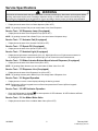
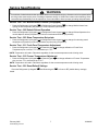
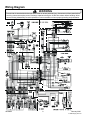
Side-by-Side Refrigerator⎯Technical Information
JCD2292KT* JCD2292KT*2, JCD2295KE* JCD2295KE*2, JCD2297KE* JCD2297KE*2,
JSD2695KES JSD2695KES2, JSD2695KG* JSD2695KG*0, JSD2697KE* JSD2697KE*2,
MSD2660KEG* MSD2660KEG*, MSD2660KES MSD2660KES0
! CAUTION
Due to a possibility of personal injury or property damage, always contact an authorized technician for
service or repair of this refrigerator. All safety information must be followed as provided in Service Manual
16025628.
!
WARNING
To avoid risk of electrical shock that can cause death or severe personal injury, disconnect unit from power
before servicing unless testing is required. Discharge capacitors through a 10,000 ohm resistor before
handling. Wires removed during disassembly must be replaced on correct terminals to ensure proper
grounding and polarization.
Kw/24 hr ±0.4
Ambient °F
22 cu ft
23 cu ft
26 cu ft
70°
1.2
1.2
1.2
90°
1.85
1.85
1.85
110°
2.6
2.6
2.6
No-Load Performance, Controls in Normal Position
Refrigerator Center
Compartment Average
Percent Run Time
Food Temperature
Cycles/24 hr
±10%
±3°F
±25%
70°
35
35
35
90°
55
55
55
110°
75
75
75
70°
24
24
24
90°
24
24
24
110°
19
19
19
70°
37
37
37
90°
39
39
39
110°
42
42
42
Freezer
Compartment
Average Food
Temperature ±3°F
70°
90°
110°
0
0
-2
0
0
-2
0
0
-2
Temperature Relationship Test Chart
Ambient °F
22 cu ft
23 cu ft
26 cu ft
Evaporator
Outlet
±3°F
70°
90°
-15
-15
-19
-15
-15
-15
Evaporator
Inlet
±3°F
70°
90°
-16
-16
-20
-16
-16
-16
Suction Line
±7°F
70°
72
72
72
90°
98
98
98
Average Total
Wattage ±10%
70°
132
132
132
90°
138
138
138
Suction
Pressure
±2 PSIG
70°
6"(Vac.)
6"(Vac.)
6"(Vac.)
90°
0
0
0
Head Pressure
± 5 PSIG
70°
87
95
87
90°
137
137
137
Schematic
February 2006
© 2006 Maytag Services
1
16026985
Component Specifications
!
WARNING
To avoid risk of electrical shock that can cause death or severe personal injury, disconnect unit from power
before servicing unless tests require power. Discharge capacitors through a 10,000-ohm resistor before
handling. Wires removed during disassembly must be replaced on correct terminals to ensure proper grounding
and polarization.
Component
Specifications all parts
115VAC/60HZ unless noted
Compressor run capacitor
Volt.....................................................
Capacitance ......................................
Compressor
BTUH .................................................
Watt ...................................................
Current Lock rotor ..............................
Current Full load ................................
Resistance Run windings...................
Resistance Start windings..................
Electric damper control
Maximum closing time ....................... 8 seconds
Temperature Rating........................... 20°F- 110°F
RPM ................................................... 5
Thermistor
Temperature
77°F....................................................
36°F ...................................................
0°F......................................................
Resistance
10,000 ohms± 1.8%
29,500 ohms± 1.0%
86,300 ohms± 1.8%
Condenser motor
Rotation (facing end opposite shaft)
RPM……………………………………
Watt....................................................
Current ...............................................
Clockwise
1120 RPM
3.4 watts±15%@115VAC
0.085 amps± 15%@115VAC
Evaporator fan motor
Rotation (facing end opposite shaft)
RPM……………………………………
Watt…………………………………….
Note: Fan blade must be fully seated
on shaft to achieve proper airflow.
Clockwise
2800 RPM
6.0 ±15% watts@115 VAC
Overload/Relay
Ult. trip amps @ 158°F (70°C) ...........
Close temperature ...........................
Open temperature............................
Short time trip (seconds)....................
Short time trip (amps @77°F (25°C) ..
2.40 amps± 15%
140°F ±10°
230°F ±5°
17 seconds ±5
12 amps ±2amps
Thermostat (Defrost)
Volt ....................................................
Watt ...................................................
Current ...............................................
Resistance across terminals:
Above 42°F ±5°..................................
Below 12°F ±7° ..................................
Volt.....................................................
Wattage .............................................
Resistance .........................................
120/240 VAC
475 watts
10/5 amps
Evaporator heater
23 cu. ft
Volt.....................................................
Wattage .............................................
Resistance .........................................
115 VAC
350 ±5% watts @ 115VAC
37.8 ±5% ohms
Control board
Volt.....................................................
120VAC, 60 HZ
See Control board troubleshooting section.
Auger Motor
Rotation (facing end opposite shaft)
Water Valve
RPM ...................................................
Watts..................................................
Power to blue and white is clockwise. Power to orange and white is
counterclockwise.
17± 3 RPM
Brown side 35w,Yellow side 20w
Super Cool Fan
Rotation (facing end opposite leads)
RPM……………………………………
Watt……………………………………
Counterclockwise
1530 ± 250
1.2 @ 12 VDC
Light switch / Interlock
Type……………………………………..
Volt………………………………………
Current…………………………………..
Resistance across leads....................
SPDT NO/NC
125/250 VAC
8/4 amps
101ohms ± 10%
Evaporator heater
22 & 26 cu. ft
Solenoid (Ice Chute)
16026985
220 VAC
15 μfd ± 10%
905 BTUH
60 Hz / 153 watts
19.0 amps± 15%
1.26 amps± 15%
3.33 ohms± 15%
4.28 ohms± 15%
Open
Closed
115 VAC
450 ±5% watts @ 115VAC
29 ±5% ohms
2
February 2006
© 2006 Maytag Services
Service Specifications
!
WARNING
To avoid risk of electrical shock that can cause death or severe personal injury, disconnect unit from power before
servicing unless tests require power. Discharge capacitors through a 10,000-ohm resistor before handling. Wires
removed during disassembly must be replaced on correct terminals to ensure proper grounding and polarization.
Programming Mode:
NOTE: The Program Code is located on the Serial Plate on this unit after the word Code.
1. Open the Fresh Food door and press and hold the Door Alarm Keypad
.
2. Press and hold Freezer Temperature Down Keypad
Door
Alarm
.
Door
Alarm
3. Release the Door Alarm Keypad
and wait 3 seconds.
4. The control will display PE to indicate the programming mode.
Freezer
Order
Fast
Ice
Refrigerator
Replace
Reset
Filter
Vacation
Mode
Temp
Alert
Door
Alarm
Max
Cool
5. Entry is confirmed by pressing the Freezer Temperature Down Keypad
once more.
6. The control will display the current Program CODE. This value should be validated with the Program CODE
printed on the unit serial plate.
Freezer
PE0
Order
Fast
Ice
Refrigerator
Replace
Reset
Filter
Vacation
Mode
Temp
Alert
Door
Alarm
Max
Cool
000
NOTE: If the Program CODE is correct, the Programming Mode is exited by closing the Refrigerator door(s).
or Refrigerator Down Keypad
to change the digit
7. Press the Refrigerator Temperature Up Keypad
value with each key press.
to select the
8. The decimal point indicates the selected digit. Press the Freezer Temperature Up Keypad
next digit.
9. Once the desired Program CODE is displayed, press and hold the Freezer Temperature Down Keypad
until the Program CODE begins flashing indicating it has been saved.
NOTE: If you attempt to enter an invalid Program CODE the control will not save the new code, but will beep. (The
unit will NOT run with a Program CODE of 0000).Once the Program CODE has been saved the
Programming Mode is exited by closing the Refrigerator door(s). If the new code is incorrect this process
should be repeated after closing the Refrigerator door(s).
The Programming mode can be exited at any time by closing the Refrigerator Door(s) or will exit if
unattended for four minutes.
Defrost Operation:
The Control Board adapts the compressor run time between defrosts to achieve optimum defrost intervals by
monitoring the length of time the defrost heater is on. After initial power up, defrost interval is 4 hours
compressor run time. Defrost occurs immediately after the 4 hours.
.
February 2006
© 2006 Maytag Services
3
16026985
Service Specifications
.
!
WARNING
To avoid risk of electrical shock that can cause death or severe personal injury, disconnect unit from power before
servicing unless tests require power. Discharge capacitors through a 10,000-ohm resistor before handling. Wires
removed during disassembly must be replaced on correct terminals to ensure proper grounding and polarization.
Forced Defrost Mode:
The forced defrost function is performed using the Freezer display and Refrigerator keypad. Enter the
Forced Defrost Mode by performing the following sequence of events:
1. Open the Fresh Food door and press and hold the Door Alarm Keypad
.
2. Press and hold Refrigerator Temperature Down Keypad
3. Release the Door Alarm Keypad
Freezer
Order
Fast
Ice
Door
Alarm
.
and wait 3 seconds. Fd appears in left display.
Refrigerator
Replace
Reset
Filter
Door
Alarm
Vacation
Mode
Door
Alarm
Temp
Alert
Max
Cool
4. Press the Refrigerator Down Keypad
again. SH appears in right display.
5. Press again to force defrost, Fd and SH will flash in display indicating unit is in defrost.
Service Test Mode:
The service test functions are performed using the refrigerator display and keypad. Enter the Service Test Mode
by performing the following sequence of events:
1. Open the Fresh Food door and press and hold the Door Alarm Keypad
.
2. Press and hold Refrigerator Temperature Up Keypad
3. Release the Door Alarm Keypad
Freezer
Order
Fast
Ice
Door
Alarm
.
and wait 3 seconds.
Refrigerator
Replace
Reset
Filter
Door
Alarm
Vacation
Mode
Temp
Alert
Door
Alarm
Max
Cool
4. Press the Refrigerator Down Keypad
again.
5. Display will show 001 in left display and numeric or dashes in right display.
and Freezer Down Keypad
to toggle through Service Test numbers.
6. Press Freezer Up Keypad
Service Test – 101 Defrost Heater & Defrost Circuit
•
Press the Refrigerator Up keypad
and Refrigerator Down keypad
to energize or de-energize the
Defrost circuit. The display will read OFF when de-energized, OP when energized with open defrost thermostat,
and CL when energized with closed defrost thermostat.
Service Test – 102 Compressor / Condenser Fan
•
Press the Refrigerator Up keypad
and Refrigerator Down keypad
Compressor/Condenser fan On and Off.
to toggle
Service Test – 111 Fresh Food Fan (if equipped)
•
Press the Refrigerator Up Keypad
and Refrigerator Down Keypad
Fresh Food Fan On and Off.
NOTE:
Display will show state OFF or DC voltage.
16026985
4
to toggle
February 2006
© 2006 Maytag Services
Service Specifications
!
WARNING
To avoid risk of electrical shock that can cause death or severe personal injury, disconnect unit from power before
servicing unless tests require power. Discharge capacitors through a 10,000-ohm resistor before handling. Wires
removed during disassembly must be replaced on correct terminals to ensure proper grounding and polarization.
Service Test – 112 Freezer Fan
Press the Refrigerator Up keypad
and Refrigerator Down keypad
NOTE: Display will show state OFF or DC voltage.
•
to toggle Freezer Fan On and Off.
Service Test – 121 Damper Operation
•
Press the Refrigerator Up keypad
and Down keypad
to toggle Damper (OP) open and (CL) closed.
NOTE: If damper is opening or closing it will not allow you to toggle damper and beep. Display will show state –CL
or –OP if Damper is in the process of closing or opening.
Service Test – 131 (3) Door Bottom Freezer Mullion Heater
•
Press the Refrigerator Up Keypad
On.
and Refrigerator Down Keypad
to toggle Mullion Heater Off and
Service Test – 141 Fresh Food Thermistor
•
Will Show Fresh Food Temperature or OP for open thermistor or SH for shorted thermistor.
Service Test – 142 Freezer Thermistor
•
Will Show Freezer Temperature or OP for open thermistor or SH for shorted thermistor.
Service Test – 143 Machine Compartment Thermistor
•
Will Show Machine Compartment Temperature or OP for open thermistor or SH for shorted thermistor.
Service Test – 151 Fresh Food Door State
•
Will show state of Fresh Food Door. OP (open) CL (closed).
NOTE: By pushing fresh food door switch you can toggle state from OP (open) to CL (closed).
Service Test – 152 Freezer Food Door State
•
Will show state of Freezer Door. OP (open) CL (closed).
NOTE: By pushing freezer door switch you can toggle state from OP (open) to CL (closed).
Service Test – 161 Cube Dispenser (if equipped)
•
Display shows the state of the Cube Dispenser (ON or OFF).
NOTE: By pushing Actuator pad you can control state of cube dispenser without opening Ice Chute door.
Service Test – 162 Crusher Dispenser (if equipped)
•
Display shows the state of the Crusher Dispenser (ON or OFF).
NOTE: By pushing Actuator pad you can control state of Crusher dispenser without opening Ice Chute door.
Service Test – 163 Water Dispenser (if equipped)
•
Display shows the state of the Water Dispenser (ON or OFF).
NOTE: By pushing Actuator pad or Bottle fill you can control state of Water dispenser.
February 2006
© 2006 Maytag Services
5
16026985
Service Specifications
!
WARNING
To avoid risk of electrical shock that can cause death or severe personal injury, disconnect unit from power before
servicing unless tests require power. Discharge capacitors through a 10,000-ohm resistor before handling. Wires
removed during disassembly must be replaced on correct terminals to ensure proper grounding and polarization.
Service Test – 164 Ice Chute Dispenser (if equipped)
•
Display shows the state of the Ice Chute dispenser (ON or OFF).
NOTE: By pushing Actuator Pad you can control state of Ice Chute Dispenser.
Service Test – 165 Dispenser Lamp (if equipped)
•
Display shows the state of the Dispenser Lamp (ON or OFF).
NOTE: By pushing Actuator Pad or Bottle Fill you can control state of dispenser lamp.
Service Test – 171 Actuator Pad (if equipped)
•
Display shows the state of the Actuator Pad (ON or OFF).
Service Test – 172 Sports Fill (if equipped)
•
Display shows the state of the Sports Fill (ON or OFF).
Service Test – 173 Ambient Light (if equipped)
•
Display shows light sensor measurement (Hi or Lo). Night light will turn on if light sensor measures Lo.
By changing the sensor’s exposure to ambient light you can control the sensor measurement.
Service Test – 174 Water Actuator Bottom Mount Internal Dispenser (if equipped)
•
Display shows the state of the Water Valve (ON or OFF).
NOTE: By pushing Water Actuator you can control state of Water Valve On or Off.
Service Test – 175 Dispenser Line (if equipped)
•
Display shows the state of the Dispenser Line (ON or OFF).
NOTE: By pushing Actuator pad or Bottle fill you can change state of Dispenser Line.
Service Test – 181 Keypad Operation
•
Display shows a numeric or letter display indicating the last key pressed.
NOTE: Refrigerator Up/Down keypads have no effect when pressed and Freezer Up/Down keypads
remain operational.
Service Test – 182 LED Indicator Operation
•
Press the Refrigerator Up Keypad
to show operation of LED Indicators. All LED Indicators will flash.
Press twice and LED will stop flashing.
Service Test – 191 Ice Maker Water Valve
•
Display shows the state of the Ice Maker Water Valve (ON or OFF).
16026985
6
February 2006
© 2006 Maytag Services
Service Specifications
!
WARNING
To avoid risk of electrical shock that can cause death or severe personal injury, disconnect unit from power before
servicing unless tests require power. Discharge capacitors through a 10,000-ohm resistor before handling. Wires
removed during disassembly must be replaced on correct terminals to ensure proper grounding and polarization.
Service Test – 201 Mullion Heater Override (if equipped)
•
Press the Refrigerator Up Keypad
or Refrigerator Down Keypad
to change Mullion Heater from
cycling on with compressor (Off position) to 100% operation (On Position).
Service Test – 202 Default Defrost Operation
•
Press the Refrigerator Up Keypad
or Refrigerator Down Keypad
to change Defrost Operation from
normal adaptive defrost (Off position) to minimum time between defrosts (On position).
Service Test – 203 Show Temperature Set points
•
Press the Refrigerator Up Keypad
or Refrigerator Down Keypad
to change from showing actual
temperature (Off position) to show temperature set points only (On position).
Service Test – 211 Fresh Food Temperature Adjustment
•
Press the Refrigerator Up Keypad
or Down Keypad
Temperature plus or minus in 1°F increments up to ± 6°F.
to change calibration of Fresh Food
NOTE: Temperature will read in Fahrenheit regardless of what current temperature scale is being used.
Service Test – 212 Freezer Temperature Adjustment
•
Press the Refrigerator Up Keypad
or Down Keypad
plus or minus 1°F in increments up to ± 6°F.
to change calibration of Freezer Temperature
NOTE: Temperature will read in Fahrenheit regardless of what current temperature scale is being used.
Service Test – 221 Reset Default Settings
Press the Refrigerator Up Keypad
and Down Keypad
to force to dEF (default factory settings).
closed.
February 2006
© 2006 Maytag Services
7
16026985
Wiring Diagram
!
WARNING
To avoid risk of electrical shock that can cause death or severe personal injury, disconnect unit from power before
servicing unless tests require power. Discharge capacitors through a 10,000-ohm resistor before handling. Wires
removed during disassembly must be replaced on correct terminals to ensure proper grounding and polarization.
16026985
8
.
February 2006
© 2006 Maytag Services