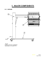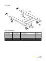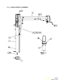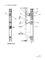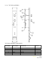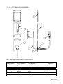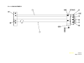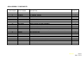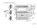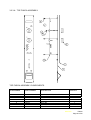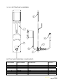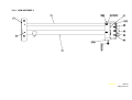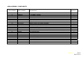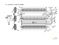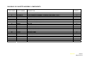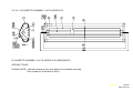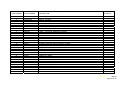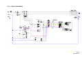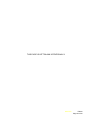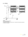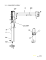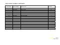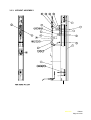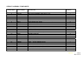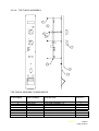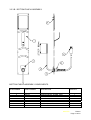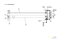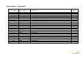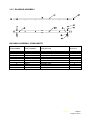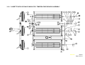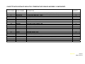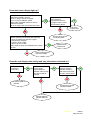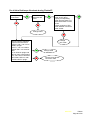
1
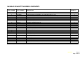
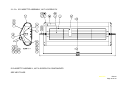
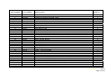
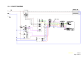
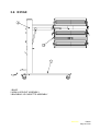
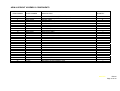
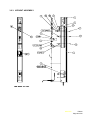
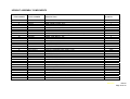
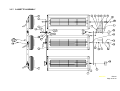
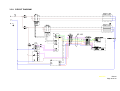
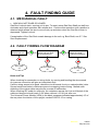
North American Curemaster with Temperature Control SERVICE MANUAL E214dt, E310dt & E516dt IF IN ANY DOUBT CONTACT: EDWIN TRISK LIMITED. MASTER FORM FM444 ISSUE 2 (VALID FROM 29/11/05) © Edwin Trisk Ltd. 2005 IMPORTANT PLEASE READ THESE INSTRUCTIONS THOROUGHLY BEFORE COMMENCING ASSEMBLY OR OPERATION OF THE UNIT. FAILURE TO DO SO COULD RESULT IN DAMAGE OR INJURY FOR WHICH EDWIN TRISK LIMITED WILL ACCEPT NO RESPONSIBILITY OR LIABILITY. THIS EQUIPMENT MUST BE EARTHED. REMOVE PACKING PIECES FROM CASSETTE HEADS BEFORE USE. THIS UNIT MUST NOT BE USED IN A SPRAY BOOTH WHERE THERE IS A POTENTIALLY FLAMMABLE ATMOSPHERE UNTIL EXTRACTION OF ANY FLAMMABLE VAPOUR IS COMPLETE. WE ALSO ADVISE CONTINUED EXTRACTION DURING CURE. DO NOT MOVE THE UNIT AROUND USING THE MAINS CABLE. DO NOT MOVE THIS UNIT DURING OPERATION AS THIS MAY LEAD TO PREMATURE EMITTER FAILURE A SUITABLY FUSE MUST BE USED TO PROTECT THE UNIT. THE UNIT SHOULD ONLY BE USED TO CURE PAINT OR PRIMER APPLIED TO METALLIC PANELS. DO NOT POINT THE UNIT AT PERSONNEL OR EASILY FLAMMABLE SUBSTANCES. ISOLATE MAINS SUPPLY BEFORE REMOVING COVERS. ISOLATE THE MAINS SUPPLY BEFORE REMOVING COVERS. THE SUPPORT ARM EXTENDS FIERCELY WHEN CASSETTE ASSEMBLY IS NOT FITTED. MASTER FM444 Page 2 of 64 IN CASE OF DAMAGE TO THE SUPPLY CORD, IT MUST NOT BE REPLACED BY THE USER AND INSTEAD QUALIFIED PERSONNEL SHOULD BE CONTACTED. TAKE CAUTION WHEN OPERATING MECHANICAL COMPONENTS – ENSURE THAT ALL BODY PARTS (THE USERS OR OTHERWISE) ARE FREE FROM WITHIN OPERATIONAL AREAS TO AVOID ENTRAPMENT. THIS MANUAL (ISSUE 01) IS ONLY INTENDED FORE THE ASSEMBLY AND OPERATION, OR THE SERVICING OF THE MODELS MENTIONED ON THE FIRST PAGE. THIS MANUAL IS AN UNCONTROLLED DOCUMENT. TRISK RESERVE THE RIGHT TO UPDATE UNIT SPECIFICATIONS WITHOUT PRIOR NOTICE OR CONSULTATION. PLEASE READ THE RELEVANT REPAIR PROCEDURE THOROUGHLY AT LEAST ONCE BEFORE COMMENCING ANY SERVICING OPERATION. SERVICING OPERATIONS SHOULD ONLY BE CARRIED OUT BY QUALIFIED PERSONNEL WHO MUST USE TRISK APPROVED COMPONENTS. IF IN ANY DOUBT ABOUT ASSEMBLY, OPERATION OR SERVICING OF THE UNIT, PLEASE DO NOT HESITATE TO CONTACT YOUR DISTRIBUTOR OR THE TRISK SERVICE DEPARTMENT. MASTER FM444 Page 3 of 64 THIS PAGE IS LEFT BLANK INTENTIONALLY MASTER FM444 Page 4 of 64 CONTENTS 1. INTRODUCTION ............................................................................................................6 1.1. SERVICING TOOLS ................................................................................................6 2. TECHNICAL SPECIFICATIONS.....................................................................................7 2.1. CUREMASTER SUPER digital ETS2dt (E214dt).....................................................7 2.2. CUREMASTER ULTRA digital ETS3dt (E310dt) .....................................................7 2.3. CUREMASTER SUPER TWIN digital ETS5dt (E516dt)...........................................7 3. MAJOR COMPONENTS ................................................................................................8 3.1. E214dt......................................................................................................................8 3.1.1. BASE .................................................................................................................9 3.1.2. ARM & UPRIGHT ASSEMBLY........................................................................10 3.1.3. UPRIGHT ASSEMBLY ....................................................................................12 3.1.4. ARM ASSEMBLY ............................................................................................16 3.1.5. BACKBAR / IR CASSETTE ASSEMBLY.........................................................18 3.1.6. CIRCUIT DIAGRAM ........................................................................................22 3.2. E310dt....................................................................................................................24 3.2.1. BASE ...............................................................................................................25 3.2.2. ARM & UPRIGHT ASSEMBLY........................................................................26 3.2.3. UPRIGHT ASSEMBLY ....................................................................................28 3.2.4. ARM ASSEMBLY ............................................................................................32 3.2.5. BACKBAR / IR CASSETTE ASSEMBLY.........................................................34 3.2.6. CIRCUIT DIAGRAM ........................................................................................38 3.3. E516dt....................................................................................................................40 3.3.1. BASE ...............................................................................................................41 3.3.2. ARM & UPRIGHT ASSEMBLY........................................................................42 3.3.3. UPRIGHT ASSEMBLY ....................................................................................44 3.3.4. ARM ASSEMBLY ............................................................................................48 3.3.5. BACKBAR ASSEMBLY ...................................................................................51 3.3.6. CASSETTE WITH DISTANCE INDICATOR / TEMPERATURE SENSOR ASSEMBLY ....................................................................................................52 3.3.7. CASSETTE ASSEMBLY .................................................................................54 3.3.8. CIRCUIT DIAGRAM ........................................................................................56 4. FAULT FINDING GUIDE ..............................................................................................58 4.1. MECHANICAL FAULT ...........................................................................................58 4.2. FAULT FINDING FLOW DIAGRAM .......................................................................58 5. REPAIR PROCEDURES ..............................................................................................61 5.1. FRONT PANEL REMOVAL....................................................................................61 5.2. MAINS CABLE REPLACEMENT ...........................................................................61 5.3. CASSETTE CORD REPLACEMENT* ...................................................................61 5.4. UPM REPLACEMENT (UNIVERSAL POWER MODULE) .....................................62 5.5. MAIN CONTROL PCB REPLACEMENT................................................................62 5.6. IEC SOCKET REPLACEMENT..............................................................................62 5.7. GAS STRUT REPLACEMENT...............................................................................62 5.8. IR EMITTER REPLACEMENT ...............................................................................63 MASTER FM444 Page 5 of 64 1. INTRODUCTION This manual is intended to aid the servicing of the TRISK branded products listed on the cover. Servicing operations should only be carried out by qualified service personnel, who must use TRISK approved components. Although every effort has been made to ensure that the following information is accurate, it is only intended to help service personnel rather than direct them in their every step. It is vitally important that any problems encountered when servicing units are referred to your importer or Edwin Trisk Ltd. PLEASE NOTE THAT WHEN SERVICING THE UNIT, REFER TO SECTION 5 - FAULT FINDING GUIDE, BEFORE COMMENCING ANY REPAIR PROCEDURE. 1.1. SERVICING TOOLS The following tools are the minimum required to service the range of products listed on the front cover: No. Required Description 1 1 1 2 2 1 1 1 1 1 1 1 1 Round, Parallel Tipped 3mm, Screwdriver Round, Parallel Tipped 5mm, Screwdriver Round, Supadrive No. 1, Screwdriver 19mm Combination Spanners 17mm Combination Spanners Hand Drill Drill 3mm diameter Combination Pliers Wire Strippers / Cutters Allen Key (6mm AF) Crimp Tool for Crimping Red, Blue and Yellow Insulated Crimp Connections Hand Rivet Gun with nozzle for 3mm rivets. Heyco Hand-pliers MASTER FM444 Page 6 of 64 2. TECHNICAL SPECIFICATIONS All units use quartz, tungsten filament, ruby sleeved Infra-Red Emitters. 2.1. CUREMASTER SUPER digital ETS2dt (E214dt) Rated Voltage: Power Consumption (nominal): Heating Elements: Area of Cover: Dimensions: Weight: 220-240V, 60Hz, 1 phase 3 emitters, full power: 3300W 3 quartz, tungsten filament, ruby sleeved Infrared Emitters 100cm x 80cm / 39” X 31” (Width) 66cm / 27”, (Height) 164cm / 66”, (Length) 150cm / 60” 50Kg / 110lbs 2.2. CUREMASTER ULTRA digital ETS3dt (E310dt) Rated Voltage: Power Consumption (nominal): Heating Elements: Area of Cover: Dimensions: Weight: 220-240V, 60Hz, 1 phase 3 emitters, full power: 4500W 3 quartz, tungsten filament, ruby sleeved Infrared Emitters 100cm x 120cm / 39” X 47” (Width) 66cm / 27”, (Height) 164cm / 66”, (Length) 150cm / 60” 50Kg / 110lbs 2.3. CUREMASTER SUPER TWIN digital ETS5dt (E516dt) Rated Voltage: Power Consumption (nominal): Heating Elements: Area of Cover: Dimensions: Weight: 220-240V, 60Hz, 1 phase 6 emitters, full power: 6000W 6 quartz, tungsten filament, ruby sleeved Infrared Emitters 100cm x 180cm / 39” X 71” (Width) 95cm / 38”, (Height) 164cm / 66”, (Length) 150cm / 60” 65Kg / 144lbs MASTER FM444 Page 7 of 64 3. MAJOR COMPONENTS 3.1. E214dt 1 BASE 2 ARM & UPRIGHT ASSEMBLY 3 BACKBAR / IR CASSETTE MASTER FM444 Page 8 of 64 3.1.1. BASE BASE COMPONENTS ITEM NUMBER 1 2 3 4 5 6 PART NUMBER DESCRIPTION E214.01 S8031 S0293A S0075D S0065 S0064 BASE WASHER, M10 NUT, NYLOCK, M10 END CAP – PLASTIC BRAKED CASTOR UNBAKED CASTOR QUANTITY 1 4 4 4 2 2 MASTER FM444 Page 9 of 64 3.1.2. ARM & UPRIGHT ASSEMBLY MASTER FM444 Page 10 of 64 ARM & UPRIGHT ASSEMBLY COMPONENTS ITEM NUMBER 1 2 3 4 5 6 7 8 9 10 11 12 13 14 15 16 17 18 19 20 21 22 23 24 25 26 27 PART NUMBER DESCRIPTION QUANTITY E214-03t E214-06t E221-02-20 141.02 PDD033 D320-03-36 177.01 S0112 S0117 E221-02-01 121.07 E221-02-21 T1040 S0118 108.04 UPRIGHT ASSEMBLY (SEE PART 3.1.3.) ARM ASSEMBLY (SEE PART 3.1.4.) COVER, SIDE NUT (GAS STRUT) PIN STRUT ARM PIN STARLOCK, CAPPED, 5/16” GAS STRUT, 800N GAS STRUT LEVER GAS STRUT END SCREW, SELF-TAPPER, No6x3/8” TOP CAP HANDLE, PLASTIC, LARGE LEVER GRIP SCREW, BUTTON HEAD, M10x15 1 1 2 1 1 1 2 1 1 1 2 1 1 1 4 S0294A S0330 NUT, NYLOCK, M12 RIVET, Ø4.8x15 2 2 S0314 194.01 WASHER, PLAIN, M12 SPACER 2 2 E214-03-24t PDD131 T1011 RATING LABEL PIVOT BOLT ASSEMBLY RATCHET LEVER, FEMALE, M12 1 1 1 MASTER FM444 Page 11 of 64 3.1.3. UPRIGHT ASSEMBLY MASTER FM444 Page 12 of 64 UPRIGHT ASSEMBLY COMPONENTS ITEM NUMBER 1 2 3 4 5 6 7 8 9 10 11 12 13 14 15 16 17 18 19 20 21 22 23 24 25 26 27 28 29 30 31 32 PART NUMBER DESCRIPTION E221-03-01 E214-04t S0161 E516-03-03 121.07 D320-03-15 S0269 E214-04-04t UPRIGHT FABRICATION TOP FASCIA ASSEMBLY (SEE PART 3.1.2.A) MCB, SINGLE POLE, 15A TRANSFORMER PCB ASSEMBLY SCREW, SELF-TAPPING, No6x3/8” UNIVERSAL POWER MODULE SCREW, M5x16 BOTTOM FASCIA ASSEMBLY (SEE PART 3.1.2.B.) S0173C 158.01 148.01 118.01 E214-03-06t E214-03-07t S0291 S0308 S0308A E221-03-08 TERMINAL BLOCK, 20A WASHER, PLASTIC, M4 NUT, PLASTIC, M4 BOLT, PLASTIC, M4 WIRING LOOM DETAIL CIRCUIT DIAGRAM (SEE PART 3.1.5.) NUT, M5 WASHER, PLAIN, M5 WASHER, STAR, M5 CABLE CLIP E221-03-28 121.09 790.01 PDD089 S0174 TERMINAL BLOCK SHROUD SCREW, SELF-TAPPER, No6x1” LABEL – EARTH SYMBOL LABEL – 1ph TERMINAL BLOCK TERMINAL BLOCK, 30A E516-03-03t S0256 282.04 E221-03-09t TRIPLE POWER SUPPLY MOUNTED ASSEMBLY SCREW, POZI-PAN, M3x8 TEMPERATURE CONTROLLER PCB TO TB MOLEX CABLE ASSEMBLY QUANTITY 1 1 1 1 15 1 1 1 7/12 2 2 2 1 REF 2 2 2 3 1 2 1 1 3+2/12 1 2 1 1 MASTER FM444 Page 13 of 64 3.1.3.A. TOP FASCIA ASSEMBLY TOP FASCIA ASSEMBLY COMPONENTS ITEM NUMBER 1 2 3 4 5 6 7 8 PART NUMBER DESCRIPTION E221-04-05t E214-04-01 D220-03-20 S0227 S0307 140.04 126.10 546.12 FASCIA PLATE FABRICATION ETS2/3 PCB ASSEMBLY, UL FASCIA LABEL TIMER KNOB WASHER, NYLON, M3 NUT, M3 SCREW, PAN HEAD, M4x10 SPACER QUANTITY 1 1 1 2 1 1 6 2 MASTER FM444 Page 14 of 64 3.1.3.B. BOTTOM FASCIA ASSEMBLY BOTTOM FASCIA ASSEMBLY COMPONENTS ITEM NUMBER 1 2 3 4 5 6 7 8 PART NUMBER DESCRIPTION E214-04-02 350.01 S0191 351.01 BTM FASCIA PANEL FABRICATION STRESS RELIEF GLAND, PG16 CABLE, 14AWG, 3-CORE GLAND NUT, PG16 S0240A PDD196 790.01 PLUG LABEL – DANGER LABEL – EARTH SYMBOL QUANTITY 1 1 6m 1 1 1 1 MASTER FM444 Page 15 of 64 3.1.4. ARM ASSEMBLY MASTER FM444 Page 16 of 64 ARM ASSEMBLY COMPONENTS ITEM NUMBER 1 2 3 4 5 6 7 8 9 10 11 12 13 14 15 16 17 18 19 20 21 22 23 24 25 26 PART NUMBER DESCRIPTION QUANTITY PDD002Y PDD002X PDD003Y CONTROL ARM SUPPORT ARM ‘U’ CHANNEL, SOCKET 1 1 1 S8032 S8031 S0293A S8030 E214-06-02 372.03 PDD040Y 121.07 PDD040X E221-06-03t S0275 S0294A S0076 S0314 PDD003X 121.21 E214-06-06 E330-06-07 S8027A PDD105 S0220B BOLT, HEX HEAD, M10x60 WASHER, PLAIN, M10 NUT, NYLOCK, M10 NUT CAP, M10 SINGLE SOCKET HOUSING ASSEMBLY IEC SOCKET TOP END CAP (SOCKET HOUSING) SCREW, POZI HEAD, No6x3/8” BOTTOM END CAP (SOCKET HOUSING) DISTANCE INDICATOR ARM CABLE (WITH TEMPERATURE CONTROL) BOLT, HEX HEAD, M12x90 NUT, NYLOCK, M12 NUT CAP, M12 WASHER, PLAIN, M12 ‘U’ CHANNEL, COLUMN SCREW, SELF-TAPPING, No4x1/2” ARM WIRING DETAILS SOCKET RETAINING CLIP ASSEMBLY SPIRAL PIN Ø10x50 LABEL – MAX VOLTAGE / AMPS CABLE TIE, MEDIUM 2 4 2 4 1 3 1 8 1 1 1 1 1 2 1 2 1 3 2 3 1 MASTER FM444 Page 17 of 64 3.1.5. BACKBAR / IR CASSETTE ASSEMBLY MASTER FM444 Page 18 of 64 BACKBAR / IR CASSETTE ASSEMBLY COMPONENTS ITEM NUMBER 1 2 3 4 5 6 7 8 9 10 11 12 13 14 15 16 17 18 19 20 21 22 23 24 25 26 27 PART NUMBER DESCRIPTION QUANTITY PDD132 BACKBAR BRACKET, LONG 1 PPA008W PPA008Y D320-05-20 PDD014Y PDD036X S8040 PDD034X S0321A S8054 S0087B S0312 S0087A 177.03 S0273 ETS2d CASSETTE ASSEMBLY, NUT FIX (SEE PART 3.1.5.A.) ETS2d CASSETTE ASSEMBLY, SCREW FIX (SEE PART 3.1.5.A.) ETS2/3d SIDE BRACKET, LONG SIDE BRACKET, SHORT SPACER BOLT, HEX HEAD, M8x30 SIDE BRACKET SPRING, RIGHT WASHER, SHAKEPROOF, M8 NUT, M8 RATCHET LEVER, FEMALE, M8 WASHER, PLAIN, M8 WING KNOB, FEMALE, M8 STARLOCK, CAPPED, 1/8” SCREW, HEX HEAD, M8x50 2 1 2 2 2 2 1 4 4 2 16 3 2 2 152.01 157.01 S0077 S0292B 395.03 S0328A S0220 S0256 E214-05t WASHER, BLACK WASHER, FIBRE NUT CAP, M8 NUT, BINX, M8 CABLE TIE MOUNT RIVET, BLACK, Ø3.2x8 CABLE TIE, SMALL SCREW, POZI TAPTITE, M3x8 USA DISTANCE INDICATOR & TEMPERATURE SENSOR ASSEMBLY 2 2 5 1 1 1 1 4 1 MASTER FM444 Page 19 of 64 3.1.5.A. IR CASSETTE ASSEMBLY, NUT & SCREW FIX IR CASSETTE ASSEMBLY, NUT & SCREW FIX COMPONENTS SEE NEXT PAGE. MASTER FM444 Page 20 of 64 ITEM NUMBER 1 2 3 4 5 6 7 8 10 11 12 13 14 15 16 17 18 19 20 21 22 23 24 25 26 31 32 33 34 35 36 37 38 40 PART NUMBER DESCRIPTION PDD072 S0251 PDD006Y PDD006W PDD007X CM01-05-20 350.05 S0173C PDD082 PDD021 370.20 PDD026 380.07 PDD161 S8049 S0332 S0328A S0309 S8008 S0561H S0220A 395.02 S0220 PDD196 S0211B S0210 385.04 S0215 S0349 S0256 3853.01 S0321A E214-07-06 PDD166 DIE CAST END CAP SCREW, SELF-TAPPER, POZI-PAN HEAD, No4x3/8” CASSETTE SIDE EXTRUSION, LONG CASSETTE BACK, LONG BACK REFLECTOR, LONG STRAIN RELIEF PLATE FLEXI STRAIN RELIEF GROMMET TERMINAL BLOCK, 20A CASSETTE CABLE TRAY, LONG SIDE REFLECTOR CORDSET LABEL – INSPECTED BY INFRA RED EMITTER TUBE, LONG, 240V, 1000W GRILLE, LONG SCREW, SOCKET HEAD CAP, M8x50 (NUT FIX ONLY) RIVET, Ø3.2x8 RIVET, Ø3.2x8, BLACK WASHER, SHAKEPROOF, M3 CABLE CLIP TUBE PACKER, 74x14x12 CABLE TIE, SNAP IN CABLE TIE BASE CABLE TIE, SMALL LABEL – ISOLATE MAINS CRIMP TERMINAL, RED MALE COUPLER CRIMP TERMINAL, R-M3-RG HEATPROOF SLEEVING, Ø12mm CRIMP TERMINAL, R-BLADE TERMINAL BLOCK RETAINING PIN SCREW, POZI-PAN TAPTITE, M3x6 HEATPROOF SLEEVING, Ø3mm WASHER, SHAKEPROOF, M8 (NUT FIX ONLY) WIRING LOOM DETAIL LABEL – CAUTION, REMOVE PACKING QUANTITY 2 8 2 1 1 1 1 3/12 1 2 1 1 1 1 2 4 6 4 2 3 4 1 1 1 2 1 45mm 2 1 3 465mm 2 1 1 MASTER FM444 Page 21 of 64 3.1.6. CIRCUIT DIAGRAM MASTER FM444 Page 22 of 64 THIS PAGE IS LEFT BLANK INTENTIONALLY MASTER FM444 Page 23 of 64 3.2. E310dt 1 BASE 2 ARM & UPRIGHT ASSEMBLY 3 BACKBAR / IR CASSETTE ASSEMBLY MASTER FM444 Page 24 of 64 3.2.1. BASE BASE COMPONENTS ITEM NUMBER 1 2 3 4 5 6 PART NUMBER DESCRIPTION E221.01 S8031 S0293A S0075D S0065 S0064 BASE WASHER, M10 NUT, NYLOCK, M10 END CAP – PLASTIC BRAKED CASTOR UNBAKED CASTOR QUANTITY 1 4 4 4 2 2 MASTER FM444 Page 25 of 64 3.2.2. ARM & UPRIGHT ASSEMBLY MASTER FM444 Page 26 of 64 ARM & UPRIGHT ASSEMBLY COMPONENTS ITEM NUMBER 1 2 3 4 5 6 7 8 9 10 11 12 13 14 15 16 17 18 19 20 21 22 23 24 25 26 27 PART NUMBER DESCRIPTION QUANTITY E310-03t E310-06t E221-02-20 141.02 PDD033 D320-03-36 177.01 550.03 S0117 E221-02-01 121.07 E221-02-21 T1040 S0118 108.04 UPRIGHT ASSEMBLY (SEE PART 3.2.3.) ARM ASSEMBLY (SEE PART 3.2.4.) COVER, SIDE NUT (GAS STRUT) PIN STRUT ARM PIN STARLOCK, CAPPED, 5/16” GAS STRUT, 1200N GAS STRUT LEVER GAS STRUT END SCREW, SELF-TAPPER, No6x3/8” TOP CAP HANDLE, PLASTIC, LARGE LEVER GRIP SCREW, BUTTON HEAD, M10x15 1 1 2 1 1 1 2 1 1 1 2 1 1 1 4 S0294A S0330 NUT, NYLOCK, M12 RIVET, Ø4.8x15 2 2 S0314 194.01 WASHER, PLAIN, M12 SPACER 2 2 E310-03-24t PDD131 T1011 RATING LABEL PIVOT BOLT ASSEMBLY RATCHET LEVER, FEMALE, M12 1 1 1 MASTER FM444 Page 27 of 64 3.2.3. UPRIGHT ASSEMBLY MASTER FM444 Page 28 of 64 UPRIGHT ASSEMBLY COMPONENTS ITEM NUMBER 1 2 3 4 5 6 7 8 9 10 11 12 13 14 15 16 17 18 19 20 21 22 23 24 25 26 27 28 29 30 31 32 PART NUMBER DESCRIPTION E221-03-01 E310-04t S0162 E516-03-03 121.07 D320-03-15 S0269 E310-04-04t 320.01 S0180A S0217B S0173C 158.01 148.01 118.01 E310-03-06t E310-03-07t S0291 S0308 S0308A E221-03-08 PDD220 E221-03-28 121.09 790.01 PDD089 S0174 E516-03-27 E516-03-03t S0256 282.04 E221-03-09t UPRIGHT FABRICATION TOP FASCIA ASSEMBLY (SEE PART 3.2.3.A.) MCB, SINGLE POLE, 30A TRANSFORMER PCB ASSEMBLY SCREW, SELF-TAPPER, No6x3/8” UNIVERSAL POWER MODULE ASSEMBLY SCREW, M5x16 BOTTOM FASCIA ASSEMBLY (SEE PART 3.2.3.B.) FUSE HOLDER, 30A, 250V AC FUSE, TIME DELAY, 15A HEATSHRINK SLEEVING, Ø6.4mm TERMINAL BLOCK, 20A WASHER, PLASTIC, M4 NUT, PLASTIC, M4 BOLT, PLASTIC, M4 WIRING LOOM DETAIL CIRCUIT DIAGRAM (SEE PART 3.2.6.) NUT, M5 WASHER, PLAIN, M5 WASHER, STAR, M5 CABLE CLIP LABEL – FUSE RATING TERMINAL BLOCK SHROUD SCREW, SELF-TAPPER, No6x1” LABEL – EARTH SYMBOL LABEL – 1ph TERMINAL BLOCK TERMINAL BLOCK, 30A TERMINAL BLOCK PACKER 24V POWER SUPPLY MOUNTED ASSEMBLY SCREW, POZI-PAN, M3x8 TEMPERATURE CONTROLLER PCB TO TB MOLEX CABLE ASSEMBLY QUANTITY 1 1 1 1 15 1 1 1 2 2 160mm 7/12 3 3 3 1 REF 2 2 2 3 1 1 2 1 1 3+2/12 1 1 2 1 1 MASTER FM444 Page 29 of 64 3.2.3.A. TOP FASCIA ASSEMBLY TOP FASCIA ASSEMBLY COMPONENTS ITEM NUMBER 1 2 3 4 5 6 7 8 PART NUMBER DESCRIPTION E310-04-05t E214-04-01 D220-03-20 S0227 S0307 140.04 126.10 546.12 FASCIA PLATE FABRICATION ETS2/3 PCB ASSEMBLY, UL FASCIA LABEL TIMER KNOB WASHER, NYLON, M3 NUT, M3 SCREW, PAN HEAD, M4x10 SPACER QUANTITY 1 1 1 2 1 1 6 2 MASTER FM444 Page 30 of 64 3.2.3.B. BOTTOM FASCIA ASSEMBLY BOTTOM FASCIA ASSEMBLY COMPONENTS ITEM NUMBER 1 2 3 4 5 6 7 8 PART NUMBER DESCRIPTION E516-04-02 350.08 S0191A 351.02 BTM FASCIA PANEL FABRICATION STRESS RELIEF GLAND, PG21 CABLE, 10AWG, 3-CORE GLAND NUT, PG21 S0240B PDD196 790.01 PLUG LABEL – DANGER LABEL – EARTH SYMBOL QUANTITY 1 1 6m 1 1 1 1 MASTER FM444 Page 31 of 64 3.2.4. ARM ASSEMBLY MASTER FM444 Page 32 of 64 ARM ASSEMBLY COMPONENTS ITEM NUMBER 1 2 3 4 5 6 7 8 9 10 11 12 13 14 15 16 17 18 19 20 21 22 23 24 25 26 PART NUMBER DESCRIPTION QUANTITY PDD002Y PDD002X PDD003Y CONTROL ARM SUPPORT ARM ‘U’ CHANNEL, SOCKET 1 1 1 S8032 S8031 S0293A S8030 E214-06-02 372.03 PDD040Y 121.07 PDD040X E221-06-03t S0275 S0294A S0076 S0314 PDD003X 121.21 E310-06-06 E330-06-07 S8027A PDD105 S0220B BOLT, HEX HEAD, M10x60 WASHER, PLAIN, M10 NUT, NYLOCK, M10 NUT CAP, M10 SINGLE SOCKET HOUSING ASSEMBLY IEC SOCKET TOP END CAP (SOCKET HOUSING) SCREW, POZI HEAD, No6x3/8” BOTTOM END CAP (SOCKET HOUSING) DISTANCE INDICATOR ARM CABLE (WITH TEMPERATURE CONTROL) BOLT, HEX HEAD, M12x90 NUT, NYLOCK, M12 NUT CAP, M12 WASHER, PLAIN, M12 ‘U’ CHANNEL, COLUMN SCREW, SELF-TAPPING, No4x1/2” ARM WIRING DETAILS SOCKET RETAINING CLIP ASSEMBLY SPIRAL PIN Ø10x50 LABEL – MAX VOLTAGE / AMPS CABLE TIE, MEDIUM 2 4 2 4 1 3 1 8 1 1 1 1 1 2 1 2 1 3 2 3 1 MASTER FM444 Page 33 of 64 3.2.5. BACKBAR / IR CASSETTE ASSEMBLY MASTER FM444 Page 34 of 64 BACKBAR / IR CASSETTE ASSEMBLY COMPONENTS ITEM NUMBER 1 3 4 5 6 7 8 9 10 11 12 13 14 15 16 19 20 21 22 23 24 25 26 27 PART NUMBER DESCRIPTION S360-06 S310-05-02 S310-05-01 D320-05-20 PDD014Y PDD036X S8040 PDD034X S0321A S8054 S0087B S0312 S0087A 177.03 S0273 152.01 157.01 S0077 S0292B 395.03 S0328A S0220 S0256 E310-05t BACKBAR BRACKET, V-LONG ETS3d CASSETTE ASSEMBLY, NUT FIX (SEE PART 3.2.4.A.) ETS3d CASSETTE ASSEMBLY, SCREW FIX (SEE PART 3.2.4.A.) ETS2/3d SIDE BRACKET, LONG SIDE BRACKET, SHORT SPACER BOLT, HEX HEAD, M8x30 SIDE BRACKET SPRING, RIGHT WASHER, SHAKEPROOF, M8 NUT, M8 RATCHET LEVER, FEMALE, M8 WASHER, PLAIN, M8 WING KNOB, FEMALE, M8 STARLOCK, CAPPED, 1/8” SCREW, HEX HEAD, M8x50 WASHER, BLACK WASHER, FIBRE NUT CAP, M8 NUT, BINX, M8 CABLE TIE MOUNT RIVET, BLACK, Ø3.2x8 CABLE TIE, SMALL SCREW, POZI TAPTITE, M3x8 USA DISTANCE INDICATOR & TEMPERATURE SENSOR ASSEMBLY QUANTITY 1 2 1 2 2 2 2 1 4 4 2 16 3 2 2 2 2 5 1 1 1 1 4 1 MASTER FM444 Page 35 of 64 3.2.5.A. IR CASSETTE ASSEMBLY, NUT & SCREW FIX IR CASSETTE ASSEMBLY, NUT & SCREW FIX COMPONENTS SEE NEXT PAGE. PLEASE NOTE: Infrared emitters do not come fitted in the cassette assembly. Part number for IR emitters is 380.11. MASTER FM444 Page 36 of 64 ITEM NUMBER 1 2 3 4 5 6 7 8 10 11 12 15 16 17 18 19 20 21 22 23 24 25 26 27 28 29 30 32 34 35 39 40 42 PART NUMBER DESCRIPTION S330-05-20 S330-05-21 S320-05-20 S330-05-23 S330-05-24 PDD021 PDD072 CM01-05-20 PDD026 PDD167 PDD041 370.05 S0173C S0349 350.05 S0256 S0251 S8049 S0332 S0328A S0321A S0309 395.02 S0220 S8008 S0220A S0561H S0211B S0210 S0215 385.01 385.04 E310-07-06 CASSETTE BACK, V-LONG BACK REFLECTOR, V-LONG GRILLE, V-LONG CASSETTE CABLE TRAY, V-LONG CASSETTE SIDE EXTRUSION, V-LONG SIDE REFLECTOR DIE CAST END CAP STRAIN RELIEF PLATE LABEL – INSPECTED BY LABEL – CAUTION, REMOVE PACKING LABEL – ISOLATE MAINS CORDSET TERMINAL BLOCK, 20A TERMINAL BLOCK RETAINING PIN FLEXI-STRAIN RELIEF GROMMET SCREW, POZI-TAPTITE, M3x8 SCREW, POZI-PAN, SELF-TAPPER, No4x3/8” SCREW, SOCKET HEAD CAP, M8x50 (NUT FIX ONLY) RIVET, Ø3.2x8 RIVET, Ø3.2x8, BLACK WASHER, SHAKEPROOF, M8 (NUT FIX ONLY) WASHER, SHAKEPROOF, M3 CABLE TIE BASE CABLE TIE, SMALL CABLE CLIP CABLE TIE, SNAP IN TUBE PACKER, 74x14x12 CRIMP TERMINAL, RED MALE COUPLER CRIMP TERMINAL, R-M3-RG CRIMP TERMINAL, R-BLADE HEATPROOF SLEEVING, Ø3mm HEATPROOF SLEEVING, Ø12mm WIRING LOOM QUANTITY 1 1 1 1 2 2 2 1 1 1 1 1 3/12 1 1 3 8 2 2 6 2 4 1 1 2 6 5 2 1 2 465mm 45mm 1 MASTER FM444 Page 37 of 64 3.2.6. CIRCUIT DIAGRAM MASTER FM444 Page 38 of 64 THIS PAGE IS LEFT BLANK INTENTIONALLY MASTER FM444 Page 39 of 64 3.3. E516dt 1 BASE 2 ARM & UPRIGHT ASSEMBLY 3 BACK BAR ASSEMBLY 4 CASSETTE WITH DISTANCE INDICATOR / TEMPERATURE SENSOR ASSEMBLY 5 CASSETTE ASSEMBLY MASTER FM444 Page 40 of 64 3.3.1. BASE BASE COMPONENTS ITEM NUMBER 1 2 3 4 5 6 PART NUMBER DESCRIPTION E321.01 S8031 S0293A S0075D S0065 S0064 BASE WASHER, M10 NUT, NYLOCK, M10 END CAP – PLASTIC BRAKED CASTOR UNBAKED CASTOR QUANTITY 1 4 4 4 2 2 MASTER FM444 Page 41 of 64 3.3.2. ARM & UPRIGHT ASSEMBLY MASTER FM444 Page 42 of 64 ARM & UPRIGHT ASSEMBLY COMPONENTS ITEM NUMBER 1 2 3 4 5 6 7 8 9 10 11 12 13 14 15 16 17 18 19 20 21 22 23 24 25 PART NUMBER DESCRIPTION QUANTITY E516-03t E516-06t E221-02-20 141.02 PDD033 D320-03-36 177.01 S0115 S0117 E221-02-01 121.07 E221-02-21 T1040 S0118 108.04 UPRIGHT ASSEMBLY (SEE PART 3.3.3.) ARM ASSEMBLY (SEE PART 3.3.4.) COVER, SIDE NUT (GAS STRUT) PIN STRUT ARM PIN STARLOCK, CAPPED, 5/16” GAS STRUT, 1500N GAS STRUT LEVER GAS STRUT END SCREW, SELF-TAPPER, No6x3/8” TOP CAP HANDLE, PLASTIC, LARGE LEVER GRIP SCREW, BUTTON HEAD, M10x15 1 1 2 1 1 1 2 1 1 1 2 1 1 1 4 S0294A S0330 NUT, NYLOCK, M12 RIVET, Ø4.8x15 2 2 S0314 194.01 WASHER, PLAIN, M12 SPACER 2 2 PDD105 E516-03-24t LABEL – MAX VOLTAGE / AMPS RATING LABEL 6 1 MASTER FM444 Page 43 of 64 3.3.3. UPRIGHT ASSEMBLY MASTER FM444 Page 44 of 64 UPRIGHT ASSEMBLY COMPONENTS ITEM NUMBER 1 2 3 4 5 6 7 8 9 10 11 12 13 14 15 16 17 18 19 20 21 22 23 24 25 26 27 28 29 30 31 32 PART NUMBER DESCRIPTION E221-03-01 E516-04t S0162 E516-03-03 121.07 D320-03-15 S0269 E516-04-04t 320.01 S0180A S0217B S0173C 158.01 148.01 118.01 E516-03-06t E516-03-07t S0291 S0308 S0308A E221-03-08 PDD220 E221-03-28 121.09 790.01 PDD089 S0174 E516-03-27 E516-03-03t S0256 282.04 E221-03-09t UPRIGHT FABRICATION TOP FASCIA ASSEMBLY (SEE PART 3.3.3.A) MCB, SINGLE POLE, 30A TRANSFORMER PCB ASSEMBLY SCREW, SELF-TAPPER, No6x3/8” UNIVERSAL POWER MODULE ASSEMBLY SCREW, M5x16 BOTTOM FASCIA ASSEMBLY (SEE PART 3.3.3.B) FUSE HOLDER, 30A, 250Vac FUSE, 15A TIME DELAY HEATSHRINK SLEEVING, Ø6.4 TERMINAL BLOCK, 20A WASHER, PLASTIC, M4 NUT, PLASTIC, M4 BOLT, PLASTIC, M4 WIRING LOOM CIRCUIT DIAGRAM (SEE 3.3.8.) NUT, M5 WASHER, PLAIN, M5 WASHER, STAR, M5 CABLE CLIP LABEL – FUSE RATING TERMINAL BLOCK SHROUD SCREW, SELF-TAPPER, No6x1” LABEL – EARTH SYMBOL LABEL – 1phase TERMINAL BLOCK TERMINAL BLOCK, 30A TERMINAL BLOCK PACKER 24V POWER SUPPLY MOUNTED ASSEMBLY SCREW, POZI-PAN, M3x8 TEMPERATURE CONTROLLER PCB TO TB MOLEX CABLE ASSEMBLY QUANTITY 1 1 1 1 15 2 1 1 2 2 160mm 7/12 3 4 3 1 REF ONLY 2 2 2 3 1 1 2 1 1 3+2/12 1 1 2 1 1 MASTER FM444 Page 45 of 64 3.2.3.A. TOP FASCIA ASSEMBLY TOP FASCIA ASSEMBLY COMPONENTS ITEM NUMBER 1 2 3 4 5 6 7 8 PART NUMBER DESCRIPTION E516-04-05t E516-04-01 E521-04-23 S0227 S0307 140.04 126.10 546.12 FASCIA PLATE FABRICATION ETS5 PCB ASSEMBLY, UL FASCIA LABEL TIMER KNOB WASHER, NYLON, M3 NUT, M3 SCREW, PAN HEAD, M4x10 SPACER QUANTITY 1 1 1 2 1 1 6 2 MASTER FM444 Page 46 of 64 3.3.3.B. BOTTOM FASCIA ASSEMBLY BOTTOM FASCIA ASSEMBLY COMPONENTS ITEM NUMBER 1 2 3 4 5 6 7 8 PART NUMBER DESCRIPTION E516-04-02 350.08 S0191A 351.02 BTM FASCIA PANEL FABRICATION STRESS RELIEF GLAND, PG21 CABLE, 10AWG, 3-CORE GLAND NUT, PG21 S0240B PDD196 790.01 PLUG LABEL – DANGER LABEL – EARTH SYMBOL QUANTITY 1 1 6m 1 1 1 1 MASTER FM444 Page 47 of 64 3.3.4. ARM ASSEMBLY MASTER FM444 Page 48 of 64 ARM ASSEMBLY COMPONENTS ITEM NUMBER 1 2 3 4 5 6 7 8 9 10 11 12 13 14 15 16 17 18 19 20 21 22 23 24 25 26 PART NUMBER DESCRIPTION PDD002Y PDD002X PDD003X E521-06-04 S8027A S8032 S8031 S0293A S8030 E516-06-03 CONTROL ARM SUPPORT ARM ‘U’ CHANNEL, COLUMN ‘U’ CHANNEL, SOCKET SPIRAL PIN, Ø10x50 BOLT, HEX HEAD, M10x60 WASHER, LAIN, M10 NUT, NYLOCK, M10 NUT CAP, M10 SOCKET HOUSING ASSEMBLY 372.03 PDD040Y 121.07 01.04.07 S0283 S0294A S0076 S0314 E221-06-03t 121.21 E516-06-06 386.02 S0078 S0355 E330-06-07 SOCKET, IEC END CAP, SOCKET HOUSING, TOP SCREW, POZI HEAD, No6x3/8” END CAP, SOCKET HOUSING, BOTTOM BOLT, HEX HEAD, M12x100 NUT, NYLOCK, M12 NUT CAP, M12 WASHER, PLAIN, M12 DISTANCE INDICATOR / TEMPERATURE SENSOR ARM CABLE SCREW, SELF-TAPPER, No4x1/2” WIRING LOOM, ARM HEATSHRINK SLEEVING, Ø19mm GROMMET STRIP GROMMET, Ø11.1 SOCKET RETAINING CLIP ASSEMBLY QUANTITY 1 1 1 1 2 2 4 2 2 1 6 1 8 1 1 1 1 2 1 2 1 120mm 2x127mm 2 6 MASTER FM444 Page 49 of 64 THIS PAGE IS LEFT BLANK INTENTIONALLY MASTER FM444 Page 50 of 64 3.3.5. BACKBAR ASSEMBLY BACKBAR ASSEMBLY COMPONENTS ITEM NUMBER 1 2 3 4 5 6 7 8 9 10 PART NUMBER DESCRIPTION E521-08-01 T1038 395.03 S0328A 790.03 790.04 S0283 S0314 S0294A S0076 BACKBAR END CAP CABLE TIE BASE RIVET, BLACK, Ø3.2x8 LABEL – GREEN LABEL – RED BOLT, M12x100 WASHER, M12 NUT, NYLOCK, M12 NUT CAP, M12 QUANTITY 1 2 6 6 1 1 2 6 2 4 MASTER FM444 Page 51 of 64 3.3.6. CASSETTE WITH DISTANCE INDICATOR / TEMPERATURE SENSOR ASSEMBLY MASTER FM444 Page 52 of 64 CASSETTE WITH DISTANCE INDICATOR / TEMPERATURE SENSOR ASSEMBLY COMPONENTS ITEM NUMBER 1 2 3 4 5 6 7 8 9 10 11 12 13 14 15 16 17 18 19 20 21 22 23 24 PART NUMBER DESCRIPTION QUANTITY PPA008W PPA008Y D320-05-20 PDD014Y PDD036X S8040 PDD034 S0321A S8054 S0087B S0312 S0087A 177.03 S0273 ETS2d CASSETTE ASSEMBLY, NUT FIX (SEE PART 3.1.5.A) ETS2d CASSETTE ASSEMBLY, SCREW FIX (SEE PART 3.1.5.A) ETS2/3d SIDE BRACKET, LONG SIDE BRACKET, SHORT SPACER BOLT, M8x30 SPRING WASHER, SHAKEPRROF, M8 NUT, M8 RATCHET LEVER, FEMALE, M8 WASHER, PLAIN, M8 WING, KNOB, FEMALE, M8 SPIDERFIX, CAPPED, 1/8” SCREW, HEX HEAD, M8x50 1 1 2 2 2 2 1 4 4 2 16 3 2 2 152.01 157.01 E521-07-05 S0256 E214-05t PPA008V S0292B S0077 WASHER, BLACK, 5/16” WASHER, FIBRE, M8 BACKBAR ASSEMBLY, LONG SCREW, POZI HEAD, TAPTITE, M3x8 DISTANCE INDICATOR / TEMPERATURE SENSOR ASSEMBLY ETS5d CASSETTE ASSEMBLY, CABLE STANDOFF, NUT FIX NUT, BINX, M8 NUT CAP, M8 2 2 1 4 1 1 1 5 MASTER FM444 Page 53 of 64 3.3.7. CASSETTE ASSEMBLY MASTER FM444 Page 54 of 64 CASSETTE ASSEMBLY COMPONENTS ITEM NUMBER 1 2 3 4 5 6 7 8 9 10 11 12 13 14 15 16 17 18 19 20 21 22 23 24 PART NUMBER DESCRIPTION QUANTITY PPA008W PPA008Y D320-05-20 PDD014Y PDD036X S8040 PDD034 S0321A S8054 S0087B S0312 S0087A 177.03 S0273 ETS2d CASSETTE ASSEMBLY, NUT FIX (SEE PART 3.1.5.A) ETS2d CASSETTE ASSEMBLY, SCREW FIX (SEE PART 3.1.5.A) ETS2/3d SIDE BRACKET, LONG SIDE BRACKET, SHORT SPACER BOLT, M8x30 SPRING WASHER, SHAKEPRROF, M8 NUT, M8 RATCHET LEVER, FEMALE, M8 WASHER, PLAIN, M8 WING, KNOB, FEMALE, M8 SPIDERFIX, CAPPED, 1/8” SCREW, HEX HEAD, M8x50 1 1 2 2 2 2 1 4 4 2 16 3 2 2 152.01 157.01 E521-07-05 WASHER, BLACK, 5/16” WASHER, FIBRE, M8 BACKBAR ASSEMBLY, LONG 2 2 1 PPA008V S0292B S0077 ETS5d CASSETTE ASSEMBLY, CABLE STANDOFF, NUT FIX NUT, BINX, M8 NUT CAP, M8 1 1 5 MASTER FM444 Page 55 of 64 3.3.8. CIRCUIT DIAGRAM MASTER FM444 Page 56 of 64 THIS PAGE IS LEFT BLANK INTENTIONALLY MASTER FM444 Page 57 of 64 4. FAULT FINDING GUIDE 4.1. MECHANICAL FAULT ARM WILL NOT RAISE OR LOWER Gas Strut Locknut slack, causing unit to jam. To reset, rotate Gas Strut Shaft one half turn clockwise and check operation with release arm. Continue this operation until a position is obtained which allows the arm to move freely up and down when the Gas Strut Lever is depressed. Tighten Locknut. If examination of the Gas Strut reveals damage to the unit e.g. Bent Shaft, see 5.7. Gas Strut Replacement. 4.2. FAULT FINDING FLOW DIAGRAM Does main timer display light up? Go to page 59 Does the unit display time setting and stay silent when switched on? Go to page 59 Do all Infra Red lamps illuminate when timer enabled? Go to page 60 Hints and Tips When checking for connection or wiring faults, try moving and bending the wire around. An insecure connection will give an intermittent fault. If all the wiring seems to be good, check the circuit boards for dry or cracked solder joints. Severe bends and kinks in cables are prone to snapping interior wiring. Melted outer shielding of the mains cable may also be a cause of malfunction. When checking IEC cable for continuity, the resistance across the Live and Neutral of the cable and lamp set should read ≥3.5Ω when cold and ≤16.0Ω just after use. The Universal Power Module (UPM) is the black component situated approximately 1/3 of the way down the interior of the upright, marked D320.03.15 on casing. MASTER FM444 Page 58 of 64 Does main timer display light up? Check continuity from mains plug to transformer board in upright: E pin on plug to E point in upright L pin on plug to ON/OFF switch Other side of ON/OFF switch to SP2 on transformer board N pin on plug to SP1 on transformer board Check continuity from SP3 & SP4 on transformer board in upright to main control board fixed to fascia Swap main control board Check following connections and continuity: >Fuse on transformer board in upright >Transformer windings >L IN to L OUT in filter >N IN to N OUT in filter Also check for short circuit between all L and N in filter Correct wiring and/or connection faults Replace faulty components Correct wiring and/or connection faults Does the unit display time setting and stay silent when switched on? Check distance indicator is connected Timer shows lines across centre Inspect distance indicator cable and its plug and socket for damage Check continuity between distance indicator socket on end of arm and CON1 on main control board Connect distance indicator Correct wiring and/or connection faults Change distance indictor cable set MASTER FM444 Page 59 of 64 Do all Infra Red lamps illuminate during Flashoff? Do any lamps illuminate? Check visually that tubes are intact Check continuity of IEC cable of OFF lamp: Unplug corresponding cable and plug back in to alternative socket on end of arm Check continuity of IEC cable between L and N in cable socket Change tubes Check continuity between: >Input N and end of arm >Input L and 1,2 & 3 IN on UPM in upright >OUT 1, 2 & 3 on UPM in upright and L out at end of arm >C on UPM in upright and SP4 on main control board >S1, S2 & S3 on UPM and SP5, SP6 & SP7 on main control board in upright Change IEC cable Change UPM Correct wiring and/or connection fault MASTER FM444 Page 60 of 64 5. REPAIR PROCEDURES 5.1. FRONT PANEL REMOVAL Ensure unit is disconnected from mains supply. Remove IR cassette assembly. Take care not to lose the fittings. For double units (ETS5d, dt) at least 2 people are recommended to remove the assembly. With the extended back c-bar it may be easier to remove each set of 3 cassettes and the backbar separately. Remove upright from base to allow the plastic side strips to be removed. Undo the four screws holding the top cap in position. Remove the four remaining screws holding the front fascia in position. The front fascia can now pivot forward allowing access to the components inside. 5.2. MAINS CABLE REPLACEMENT Ensure unit is disconnected from mains supply (remove mains plug from the supply). Remove the six screws that hold the cable gland cover to the upright column. The cover can be eased away from the column exposing the connections to the mains cable. Disconnect the mains input cable from the terminal block. Release the clamping screws on the cable clamps and cut the tie wrap holding the cable to the terminal block. Disconnect the earth cable from the cover earth stud. Undo the clamping nut on the spiral gland to release the old mains lead. To refit the new mains cable, ensure the new cable is the same type as the original. Strip the sheath 270mm back from the end before inserting into the cable gland. Fasten the cable clamp onto the sheath of the mains cable allowing a minimum of 5mm to extend beyond the clamp. Refit the cable tie to tidy cables. Tighten nut of spiral gland. Connect as below: Black White Green - Live (Terminal marked L) - Neutral (Terminal marked N) - Earth (Terminal marked E) 5.3. CASSETTE CORD REPLACEMENT* *The Cassette Cord is usually supplied as part of a spares package, complete with Strain Relief Plate and associated components. The following procedure details the steps of replacing just the Cassette Cord itself. Ensure unit is disconnected from the mains supply. Disconnect Cassette Cords from IEC Sockets. Remove the affected IR Cassette Assembly from the end of the arm by removing the ratchet lever. Carefully support IR Cassette Assembly and slide this unit off the pivot bolt. Examination of the rear of the affected IR Cassette will show the cord entering the unit via MASTER FM444 Page 61 of 64 a spiral gland mounted on a Strain Relief Plate. Drill out the four rivets which hold the Strain Relief Plate to the Back Mesh, and the central rivet that holds the Earth Terminal to the Strain Relief Plate. A record should be made of the connections to the Terminal Block before removing old cable. A pair of Heyco hand pliers are usually required for removing and fitting the Spiral Gland but normal can be used if necessary. Fit new cord. Re-attach the cassette earth terminal. Rivet the Strain Relief Plate onto Back Mesh. The unit is now ready for re-assembly 5.4. UPM REPLACEMENT (UNIVERSAL POWER MODULE) Ensure unit is disconnected from the mains supply. See procedure 1 for removal of front panel. Do not disconnect the old UPM until the new one is in place. The UPM can be swapped by first removing the two securing screws. The new UPM can then be fixed into position, (once thermally conductive paste has been applied). The cabling can then be swapped over, being careful to connect correctly. 5.5. MAIN CONTROL PCB REPLACEMENT Ensure unit is disconnected from the mains supply. See procedure 1 for removal of front panel. Do not disconnect the old control PCB until the new one is in place. Undo the M3 nut located near the six-pin connector. Undo the six screws fixing the control PCB to the front panel. Remove knobs on front of panel. Fix new control PCB in position and carefully swap the interconnections from the old control PCB to the new. 5.6. IEC SOCKET REPLACEMENT Ensure unit is disconnected from mains supply. Remove cassette assembly / pivot bolt assembly. To remove the plastic covers at the end of the arm undo the 8 screws fixing them. Remove Plastic Caps, which cover bolts that attach socket housing to arm ‘U’ Channel. Slacken M10 Lock-nuts sufficiently to allow the Socket Housing to slide off and give access to the sockets. Do not use excessive force or the wires will be damaged. Take a note of the wiring connections to the damaged socket then remove wires and unclip socket. Clip the new socket into housing and refit cables. Refit Socket Housing to arm. 5.7. GAS STRUT REPLACEMENT Ensure unit is disconnected from mains supply. Check rating of replacement Gas Strut is correct (if in doubt, check rating on old gas strut). MASTER FM444 Page 62 of 64 Remove cassette assembly, remove upright from base and remove side strips. Remove the self – tapping screws that secure the Plastic Cap on the top of Upright. Remove the 2 plastic covers from the side of the Upright. Carefully support the cassette assembly on a stand or bench. Remove the capped starlock from one side of the pin assembly that fasten the Gas Strut to the support arm. (A new capped starlock will probably be needed) Push out the lower Gas Strut Pivot Pin. Rotate the Gas Strut and remove from the Upright. Replace with a TRISK pre-prepared Gas Strut. Replace the lower Gas Strut Pivot Pin. Adjust the support arm height to suit the new Gas Strut setting. Reassemble holding collar arrangement and fix in place with new split pin. CAUTION: Once fitted, Gas Strut should only be tested with IR Cassettes in place. Check that Gas Strut operation is satisfactory. 5.8. IR EMITTER REPLACEMENT Check that replacement emitter has correct voltage and wattage ratings. Check old emitter end caps if in doubt. Ensure unit is disconnected from mains supply. Remove wire Grille from front of IR Cassette. Remove Self Tapping Screws, which hold Side Reflectors onto cassette. A small screwdriver will be necessary to lift the side reflector from the cassette. When the Side Reflectors are removed, take note of the cable positions before removing old emitter. The In-Line connector can be separated by hand, but a better solution is to use two pairs of pliers. One to hold each connector when separating the wires. Fit new Infra-Red Emitter to sockets in cassette. To avoid touching the ruby sleeve with bare hands use tissue paper when handling the emitter. Reconnect Infra-Red Emitter to cassette wiring, taking care to replace the wires in the original positions. Fit side reflectors then clean ruby sleeve and Reflectors with IPA or Methylated Spirits. Refit Grille. Allow 15 minutes for the solvent to dissipate before switching on. MASTER FM444 Page 63 of 64 FM 444 ISSUE 2 © Edwin Trisk Ltd 2005 TRISK USA EQUIPMENT SALES, SPARES, SERVICE, WARRANTY & REPAIRS Call toll free on 1-866-79-TRISK (1-866-798-7475) Email: [email protected] EDWIN TRISK LTD PALLION INDUSTRIAL ESTATE SUNDERLAND TYNE AND WEAR SR4 6SN ENGLAND TEL: +44 (0) 191 510 0992 FAX: +44 (0) 191 510 0689 E-mail: [email protected] www.trisk.co.uk MASTER FM444 Page 64 of 64