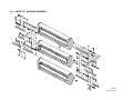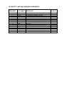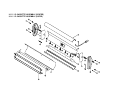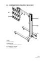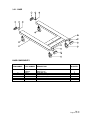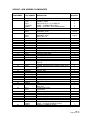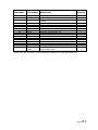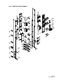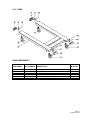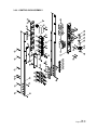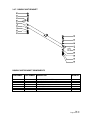
1
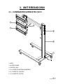
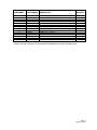
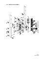
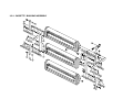
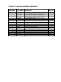
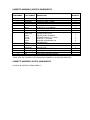
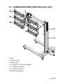
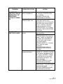
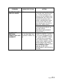
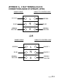
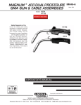
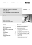
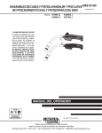
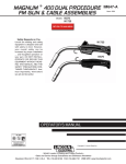
EUROPEAN CUREMASTER SERVICE MANUAL ETS2, ETS3 & ETS5 PGA001, S2/21, S3/20, S3/21 (PGA004) S5/20, S5/21 FORM FM 72 ISSUE 6 (VALID FROM 22/09/04) © Edwin Trisk Ltd.2004 IMPORTANT PLEASE READ THESE INSTRUCTIONS THOROUGHLY BEFORE COMMENCING ASSEMBLY OR OPERATION OF THE UNIT. FAILURE TO DO SO COULD RESULT IN DAMAGE OR INJURY, FOR WHICH EDWIN TRISK LIMITED WILL ACCEPT NO RESPONSIBILITY OR LIABILITY. THIS EQUIPMENT MUST BE EARTHED. REMOVE ALL PACKING PIECES FROM EACH CASSETTE HEAD BEFORE USE. THIS UNIT MUST NOT BE USED IN A SPRAY BOOTH WHERE THERE IS A POTENTIALLY FLAMMABLE ATMOSPHERE UNTIL EXTRACTION OF ANY FLAMMABLE VAPOUR IS COMPLETE. WE ALSO ADVISE CONTINUED EXTRACTION DURING CURE. DO NOT MOVE THE UNIT AROUND USING THE MAINS CABLE. DO NOT MOVE THIS UNIT DURING OPERATION AS THIS MAY LEAD TO PREMATURE EMITTER FAILURE. ALLOW UNIT TO COOL FIRST. A SUITABLY RATED FUSE MUST BE USED TO PROTECT THE UNIT. THIS UNIT SHOULD ONLY BE USED TO CURE PAINT AND PRIMER APPLIED TO METALLIC PANELS. DO NOT POINT THE UNIT AT ANY LIVING BEING. DO NOT POINT THE UNIT AT ANY EASILY FLAMMABLE SUBSTANCES. ISOLATE MAINS SUPPLY BEFORE REMOVING COVERS. THE SUPPORT ARM EXTENDS FIERCELY WHEN CASSETTE ASSEMBLY IS NOT FITTED. FM 72 Page 2 of 64 IN CASE OF DAMAGE TO THE SUPPLY CORD, THE USER MUST NOT REPLACE IT. INSTEAD, QUALIFIED PERSONNEL SHOULD BE CONTACTED. TAKE CAUTION WHEN OPERATING MECHANICAL COMPONENTS – ENSURE THAT ALL BODY PARTS (THE USRE’S OR OTHERWISE) ARE FREE FROM WITHIN OPERATIONAL ARES TO AVOID ENTRAPMENT. THIS MANUAL (ISSUE 06) IS ONLY INTENDED FOR THE ASSEMBLY AND OPERATION, OR THE SERVICING OF THE MODELS MENTIONED ON THE FIRST PAGE. THIS MANUAL IS AN UNCONTROLLED DOCUMENT. TRISK RESERVE THE RIGHT TO UPDATE UNIT SPECIFICATIONS WITHOUT PRIOR NOTICE OR CONSULTATION. PLEASE READ THE RELEVANT REPAIR PROCEDURE THOROUGHLY AT LEAST ONCE BEFORE COMMENCING ANY SERVICING OPERATION. SERVICING OPERATIONS SHOULD ONLY BE CARRIED OUT BY QUALIFIED SERVICE PERSONNEL WHO MUST USE TRISK APPROVED COMPONENTS. IF IN ANY DOUBT ABOUT ASSEMBLY OR OPERATION OF THE UNIT, PLEASE DO NOT HESITATE TO CONTACT YOUR DISTRIBUTOR OR THE TRISK SERVICE DEPARTMENT. FM 72 Page 3 of 64 THIS PAGE IS LEFT BLANK INTENTIONALLY. FM 72 Page 4 of 64 CONTENTS 1. INTRODUCTION ............................................................................................................6 1.1. SERVICING TOOLS ................................................................................................6 2. TECHNICAL SPECIFICATIONS.....................................................................................7 2.1. CUREMASTER SUPER ETS2 (S2/21) ....................................................................7 2.2. CUREMASTER ULTRA ETS3 (S3/20, S3/21) .........................................................7 2.3. CUREMASTER SUPER TWIN ETS5 (S5/20, S5/21)...............................................7 3. UNIT BREAKDOWN.......................................................................................................8 3.1. CUREMASTER SUPER ETS2: S2/21 .....................................................................8 3.1.1. BASE .................................................................................................................9 3.1.2. UPRIGHT / ARM ASSEMBLY ......................................................................... 10 3.1.3. CONTROL BOX ASSEMBLY .......................................................................... 14 3.1.4. CASSETTE / BACKBAR ASSEMBLY ............................................................. 16 3.1.5. I.R. CASSETTE ASSEMBLY (CENTRE)......................................................... 18 3.1.6. I.R. CASSETTE ASSEMBLY (OUTER) ........................................................... 18 3.2. CUREMASTER ULTRA ETS3: S3/20, S3/21......................................................... 20 3.2.1. BASE ............................................................................................................... 21 3.2.2. UPRIGHT / ARM ASSEMBLY ......................................................................... 22 3.2.3. CONTROL BOX ASSEMBLY .......................................................................... 26 3.2.4. CASSETTE / BACKBAR ASSEMBLY ............................................................. 28 3.2.5. I.R. CASSETTE ASSEMBLY (CENTRE)......................................................... 30 3.2.6. I.R. CASSETTE ASSEMBLY (OUTER) ........................................................... 30 3.3. CUREMASTER SUPER TWIN ETS5: S5/20, S5/21 .............................................. 32 3.3.1. BASE ............................................................................................................... 33 3.3.2. UPRIGHT / ARM ASSEMBLY ......................................................................... 34 3.3.3. CONTROL BOX ASSEMBLY .......................................................................... 38 3.3.4. I.R. CASSETTE / BACKBAR ASSEMBLY....................................................... 40 3.3.5. I.R. CASSETTE ASSEMBLY (CENTRE)......................................................... 42 3.3.6. I.R. CASSETTE ASSEMBLY (OUTER) ........................................................... 42 3.3.7. DOUBLE UNIT BRACKET............................................................................... 44 4. FAULT FINDING GUIDE .............................................................................................. 45 5. REPAIR PROCEDURES .............................................................................................. 48 5.1. REMOVAL OF CONTROL BOX FROM UPRIGHT ................................................ 48 5.2. MAINS CABLE REPLACEMENT ........................................................................... 49 5.3. CASSETTE CORD REPLACEMENT*.................................................................... 49 5.4. CONTACTOR REPLACEMENT............................................................................. 50 5.5. TIMER REPLACEMENT ........................................................................................ 51 5.6. IEC SOCKET REPLACEMENT.............................................................................. 51 5.7. GAS STRUT REPLACEMENT............................................................................... 52 5.8. I.R EMITTER REPLACEMENT .............................................................................. 52 6. APPENDICES............................................................................................................... 54 FM 72 Page 5 of 64 1. INTRODUCTION This manual is intended to aid the servicing of the TRISK branded products listed on the cover. Servicing operations should only be carried out by qualified service personnel who must use TRISK approved components. Although every effort has been made to ensure that the following information is accurate, it is only intended to help service personnel rather than direct them in their every step. It is vitally important that any problems encountered when servicing units are referred to your importer. PLEASE NOTE THAT WHEN SERVICING THE UNIT, REFER TO SECTION 5; FAULT FINDING GUIDE, BEFORE COMMENCING ANY REPAIR PROCEDURE. 1.1. SERVICING TOOLS The following tools are the minimum required to service the range of products listed on the front cover; No. Required 1 1 1 2 2 1 1 1 1 1 1 1 1 Description Round, Parallel tipped 3mm, Screwdriver Round, Parallel tipped 5mm, Screwdriver Round, Supadrive No. 1, Screwdriver 19mm Combination Spanners 17mm Combination Spanners Stanley Hand Drill Drill 3mm diameter Combination Pliers Wire Strippers / Cutters Allen Key (6mm AF) Crimp Tool for Crimping Red, Blue and Yellow Insulated Crimp Connections Hand Rivet Gun with nozzle for 3mm rivets. Heyco Hand-pliers FM 72 Page 6 of 64 2. TECHNICAL SPECIFICATIONS 2.1. CUREMASTER SUPER ETS2 (S2/21) Rated Voltage Power Consumption (nominal) Heating elements: Area of cover: Dimensions: Weight: 230V, 50Hz, 1 Phase 3 emitters, full power: 3300W 3 quartz, tungsten filament ruby-sleeved Infra-Red Emitters 100cm x 80cm (Width): 66cm, (Height): 164cm, (Length): 150cm 50Kg 2.2. CUREMASTER ULTRA ETS3 (S3/20, S3/21) Rated Voltage Power Consumption (nominal) Heating elements: Area of cover: Dimensions: Weight: 230V, 50Hz, 1 Phase 3 emitters, full power: 4500W 3 quartz, tungsten filament ruby-sleeved Infra-Red Emitters 100cm x 120cm (Width): 66cm, (Height): 164cm, (Length): 150cm 50Kg 2.3. CUREMASTER SUPER TWIN ETS5 (S5/20, S5/21) Rated Voltage Power Consumption (nominal) Heating elements: Area of cover: Dimensions: Weight: 400V, 50Hz, 3 Phase + N 6 emitters, full power: 6600W 6 quartz, tungsten filament ruby-sleeved Infra-Red Emitters 100cm x 180cm (Width): 66cm, (Height): 164cm, (Length): 150cm 70Kg FM 72 Page 7 of 64 3. UNIT BREAKDOWN 3.1. CUREMASTER SUPER ETS2: S2/21 1 BASE 2 UPRIGHT/ARMS 3 CONTROL BOX 4 I.R. CASSETTE/BACKBAR ASSEMBLY 5 I.R. CASSETTE (CENTRE) 6 I.R. CASSETTE (OUTER) FM 72 Page 8 of 64 3.1.1. BASE BASE COMPONENTS ITEM NUMBER 1 2 3 4 5 6 PART NUMBER DESCRIPTION S360.01 S8031 S0293A S0075D S0065 S0064 BASE WASHER, M10 LOCKNUT, M10, NYLOC ENDCAP, PLASTIC BRAKED CASTOR UNBRAKED CASTOR QUANTITY 1 4 4 4 2 2 FM 72 Page 9 of 64 3.1.2. UPRIGHT / ARM ASSEMBLY FM 72 Page 10 of 64 UPRIGHT / ARM ASSEMBLY COMPONENTS ITEM NUMBER PART NUMBER DESCRIPTION 6 7 8 9 10 11 12 13 14 15 16 17 18 19 PDD001 PDD002X PDD023 PDD195 PDD002Y PDD003X PDD003Y S0078 S0275 S8027A S8032 S8031 S0293A S8030 PPA021 372.03 PDD040Y PDD040X T1033 S0076 S0314 PDD036W S0251C 20 21 N/A S8028 22 23 24 25 26 27 28 29 30 31 S0294A PDD012X PDD012Y PDD042 S8040 S0312 S0292A PDD011 PDD033 S0112 32 S0117 S0118 S0116 177.01 194.01 D320.03.36 PDD043 S0077 PDD087 PDD071 S0173C S0294C S0257 UPRIGHT COLUMN SUPPORT ARM LABEL – ‘CUREMASTER SUPER’ LABEL – ‘CAUTION – THIS ARM EXTENDS’ CONTROL ARM ‘U’ CHANNEL – COLUMN ‘U’ CHANNEL – SOCKET GROMMET STRIP BOLT, M12 x 90 ROLL PIN Ø10 x 50 BOLT, M10 x 60 WASHER, M10 LOCKNUT, M10 NUT CAP, M10 SOCKET HOUSING IEC SOCKET TOP END CAP, SOCKET HOUSING BOTTOM END CAP, SOCKET HOUSING LOCKNUT, M12, BINX NUT CAP, M12 WASHER, M12 SPACER SCREW, SELF TAPPING, POZI HEAD, No8 x 1/2”, TYPE B THIS ITEM IS FACTORY FITTED* SCREW, COUNTERSUNK, SOCKET HEAD, M10 x 20 LOCKNUT, M12 COVER, SIDE COVER, FRONT TOP CAP, UPRIGHT BOLT, M8 x 30 WASHER, M8 LOCKNUT, M8 PIVOT BRACKET PIN GAS STRUT, 800N HALF NUT LEVER, GAS STRUT LEVER END END, GAS STRUT CAPPED STARLOCK, 5/16” SPACER STRUT ARM PIN COLUMN TOP BRACKET NUT CAP, M8 SHROUD, TERMINAL BLOCK BRACKET, TERMINAL BLOCK TERMINAL BLOCK, 20A, 3-WAY HALF NUT, M12 SCREW, COUNTERSUNK, POZI HEAD, No8 x 1/2”, TYPE B 1 2 3 4 5 33 34 35 36 37 38 39 40 41 42 43 QUANTITY 1 1 2 2 1 1 1 2 x127mm 1 2 2 4 2 4 1 3 1 1 1 1 3 1 10 4 2 1 1 1 1 2 1 1 1 1 1 1 1 2 2 1 1 1 1 1 1 1 4 FM 72 Page 11 of 64 ITEM NUMBER 44 45 46 47 48 49 50 51 52 53 54 55 56 57 PART NUMBER DESCRIPTION S0512 S0513 S0269 S0291 S0308 S0308A S0250 S0298 S0307 S0220A 370.16 PDD139 PDD140 PDD141 STRAIN RELIEF GLAND, SPIRAL, M20 CONCLAMP, TYPE B, M20 SCREW, HEX HEAD, M5 x 16 NUT, M5 WASHER, M5 WASHER, SHAKEPROOF, M5 SCREW, NYLON, M3 x 25 NUT, NYLON, M3 WASHER, NYLON, M3 CABLE TIE – SNAP IN CABLE – MAINS INPUT SIDE COVER STRIP, LOWER SIDE COVER STRIP, UPPER CABLE HANGER QUANTITY 1 1 1 1 1 1 2 2 4 1 6m 1 1 1 *ITEMS THAT ARE FACTORY FITTED CANNOT BE ORDERED AS A PRE-PREPARED PART. FM 72 Page 12 of 64 THIS PAGE IS LEFT BLANK INTENTIONALLY. FM 72 Page 13 of 64 3.1.3. CONTROL BOX ASSEMBLY FM 72 Page 14 of 64 CONTROL BOX ASSEMBLY COMPONENTS ITEM NUMBER 1 2 3 4 5 6 7 8 9 10 11 12 13 14 15 16 17 18 19 20 21 22 23 24 25 26 PART NUMBER DESCRIPTION PDD048 PDD062X PDD062Y PDD066X PDD049 S0352 PDD050 S0352 PDD051 PDD073 S0328A S0355 PDD057 PDD056 321.01 PDD058 PDD080 S0185 S0161 S8068C S0228 S0241 S0173C S0182 S0182A S0340B S0349 S0328A S0256 S0227 S0340A S0330 S0311 N/A FASCIA PANEL LABEL – ‘FLASH OFF 50Hz’ LABEL – ‘FULL BAKE 50Hz’ LABEL - SWITCHES SIDE SHEET, RIGHT HAND (LONG) POLYESTER INSULATING TAPE SIDE SHEET, LEFT HAND (LONG) POLYESTER INSULATING TAPE BASE (LONG) DIN RAIL BRACKET RIVET Ø3.2 x 6 GROMMET, Ø11.1 HEAT SINK HEAT SINK SPACER (SHORT) FILTER CONTACTOR SHORTING LINK HEAT SINK GRILLE (LONG) SWITCH CIRCUIT BREAKER CONTACTOR TIMER (50Hz) DIODE TERMINAL BLOCK, 20A, 3-WAY INDICATOR, RED INDICATOR, AMBER POP RIVET Ø4.8 x 12, NYLON RETAINING PIN POP RIVET Ø3.2 x 8 SCREW, POZI DRIVE HEAD, TAPTITE, M3 x 8 TIMER KNOB P-CLIP, Ø7.5 CABLE POP RIVET Ø4.8 x 15, ALUMINIUM SCREW, PAN HEAD, M4 x 4 THIS ITEM IS FACTORY FITTED* QUANTITY 1 1 1 1 1 1.5m 1 1.5m 1 2 18 2 1 1 1 4 1 3 1 2 2 1 1 2 1 4 2 20 1 2 2 3 4 *ITEMS THAT ARE FACTORY FITTED CANNOT BE ORDERED AS A PRE-PREPARED PART. FM 72 Page 15 of 64 3.1.4. CASSETTE / BACKBAR ASSEMBLY FM 72 Page 16 of 64 IR CASSETTE / BACKBAR ASSEMBLY COMPONENTS ITEM NUMBER 1 2 3 4 5 6 7 8 9 10 11 12 13 14 15 16 PART NUMBER DESCRIPTION PDD132 PPA017 PPA016 PDD014X PDD014Y PDD036X S8051 PDD034X S0321A S8054 S0087B S0312 S0087A S8053 S8052 PDD034Y BACKBAR (LONG) IR CASSETTE ASSEMBLY (CENTRE) IR CASSETTE ASSEMBLY (OUTER) SIDE BRACKET, LONG SIDE BRACKET, SHORT SPACER SCREW, COUNTERSUNK SOCKET HEAD, M8 x 35 SPRING, RIGHT HAND SIDE BRACKET WASHER, SHAKEPROOF, M8 NUT, M8 RATCHET LEVER, FEMALE WASHER, M8 WING KNOB, FEMALE WASHER, CAPPED STARLOCK, M3 SCREW, COUNTERSUNK SOCKET HEAD, M8 x 45 SPRING, LEFT HAND SIDE BRACKET QUANTITY 1 1 2 2 4 4 4 2 14 6 2 26 4 8 4 2 3.1.5. I.R. CASSETTE ASSEMBLY (CENTRE) 3.1.6. I.R. CASSETTE ASSEMBLY (OUTER) CASSETTE ASSEMBLY (CENTRE) COMPONENTS ITEM NUMBER 1 2 3 4 5 6 7 8 9 10 11 12 13 14 PART NUMBER DESCRIPTION PDD072 S0251 PDD006Y PDD006W PDD007X S0332 PDD082 PDD021 370.05 CM01.05.20 350.05 S0173C S0349 380.08 PDD161 S8049 S8008 S0220A N/A END CAP SCREW, SELF TAPPING, No4 x 3/8” CASSETTE SIDE (LONG) CASSETTE BACK MESH (LONG) BACK REFLECTOR (LONG) RIVET Ø3.2 x 8 CABLE TRAY (LONG) SIDE REFLECTOR PLUG/CORDSET STRAIN RELIEF PLATE STRAIN RELIEF GROMMET TERMINAL BLOCK, 20A, 3-WAY RETAINING PIN I.R. EMITTER GRILLE SCREW, CAP HEAD SET, M8 x 50 CABLE CLIP CABLE TIE – SNAP IN THIS ITEM IS FACTORY FITTED* *ITEMS THAT ARE FACTORY FITTED CANNOT BE ORDERED AS A PRE-PREPARED PART. CASSETTE ASSEMBLY (OUTER) COMPONENTS AS ABOVE BUT WITHOUT ITEM NUMBER 11 QUANTITY 2 10 2 1 1 10 1 2 1 1 1 1 1 1 1 2 2 4 3.2. CUREMASTER ULTRA ETS3: S3/20, S3/21 1 BASE 2 UPRIGHT/ARMS 3 CONTROL BOX 4 I.R. CASSETTE/BACKBAR ASSEMBLY 5 I.R. CASSETTE (CENTRE) 6 I.R. CASSETTE (OUTER) FM 72 Page 20 of 64 3.2.1. BASE BASE COMPONENTS ITEM NUMBER 1 2 3 4 5 6 PART NUMBER DESCRIPTION S360.01.01 PDD190 S8031 S0293A S0075D S0065 S0064 BASE (S3/20) BASE (S3/21) WASHER, M10 LOCKNUT, M10, NYLOC ENDCAP, PLASTIC BRAKED CASTOR UNBRAKED CASTOR QUANTITY 1 1 4 4 4 2 2 FM 72 Page 21 of 64 3.2.2. UPRIGHT / ARM ASSEMBLY FM 72 Page 22 of 64 UPRIGHT / ARM ASSEMBLY COMPONENTS ITEM NUMBER PART NUMBER DESCRIPTION 6 7 8 9 10 11 12 13 14 15 16 17 18 19 PDD253 PDD002X T1040 S0330 S330.02.20 PDD085 PDD002Y PDD003X S0078 PDD003Y S0078 S0275 S8027A S8032 S8031 S0293A S8030 PPA021 372.03 PDD040Y PDD040X T1033 S0076 S0314 PDD036W S0251C 20 21 N/A S8028 22 23 24 25 26 27 28 29 30 31 S0294A PDD012X PDD012Y PDD042 S8040 S0312 S0292A PDD011 PDD033 550.03 32 S0117 S0118 S0116 177.01 194.01 D320.03.36 PDD043 S0077 PDD087 PDD088 PDD071 UPRIGHT COLUMN SUPPORT ARM HANDLE, LARGE POP RIVET Ø4.8 x 15, ALUMINIUM LABEL – ‘CUREMASTER ULTRA’ LABEL – ‘CAUTION – THIS ARM EXTENDS’ CONTROL ARM ‘U’ CHANNEL – COLUMN GROMMET STRIP ‘U’ CHANNEL – SOCKET GROMMET STRIP BOLT, M12 x 90 ROLL PIN Ø10 x 50 BOLT, M10 x 60 WASHER, M10 LOCKNUT, M10 NUT CAP, M10 SOCKET HOUSING IEC SOCKET TOP END CAP, SOCKET HOUSING BOTTOM END CAP, SOCKET HOUSING LOCKNUT, M12, BINX NUT CAP, M12 WASHER, M12 SPACER SCREW, SELF TAPPING, POZI HEAD, No8 x 1/2”, TYPE B THIS ITEM IS FACTORY FITTED* SCREW, COUNTERSUNK, SOCKET HEAD, M10 x 20 LOCKNUT, M12 COVER, SIDE COVER, FRONT TOP CAP, UPRIGHT BOLT, M8 x 30 WASHER, M8 LOCKNUT, M8 PIVOT BRACKET PIN GAS STRUT, 1200N HALF NUT LEVER, GAS STRUT LEVER END END, GAS STRUT CAPPED STARLOCK, 5/16” SPACER STRUT ARM PIN COLUMN TOP BRACKET NUT CAP, M8 SHROUD, TERMINAL BLOCK LABEL – ‘3 PHASE TERMINAL BLOCK’ BRACKET, TERMINAL BLOCK 1 2 3 4 5 33 34 35 36 37 38 39 40 QUANTITY 1 1 1 2 2 2 1 1 127mm 1 127mm 1 2 2 4 2 2 1 3 1 1 1 1 4 1 10 4 2 1 1 1 1 2 1 1 1 1 1 1 1 2 2 1 1 1 1 1 1 FM 72 Page 23 of 64 ITEM NUMBER PART NUMBER DESCRIPTION 41 42 43 S0173C S0294C S0257 44 45 46 47 48 49 50 51 52 53 54 55 56 57 350.01 351.01 S0269 S0291 S0308 S0308A S0250 S0298 S0307 S0220A 300.13 PDD139 PDD140 PDD142 T1050A TERMINAL BLOCK, 20A, 5-WAY HALF NUT, M12 SCREW, COUNTERSUNK, POZI HEAD, No8 x 1/2”, TYPE B STRAIN RELIEF GLAND, SPIRAL, PG16 GLAND NUT, PG16 SCREW, HEX HEAD, M5 x 16 NUT, M5 WASHER, M5 WASHER, SHAKEPROOF, M5 SCREW, NYLON, M3x25 NUT, NYLON, M3 WASHER, NYLON, M3 CABLE TIE – SNAP IN CABLE – MAINS INPUT SIDE COVER STRIP, LOWER SIDE COVER STRIP, UPPER CABLE HANGER PLUG, MAINS (S3/21) QUANTITY 1 1 4 1 1 1 1 1 1 2 2 4 1 6m 1 1 1 1 *ITEMS THAT ARE FACTORY FITTED CANNOT BE ORDERED AS A PRE-PREPARED PART. FM 72 Page 24 of 64 THIS PAGE IS LEFT BLANK INTENTIONALLY. FM 72 Page 25 of 64 3.2.3. CONTROL BOX ASSEMBLY FM 72 Page 26 of 64 CONTROL BOX ASSEMBLY COMPONENTS ITEM NUMBER 1 2 3 4 5 6 7 8 9 10 11 12 13 14 15 16 17 18 19 20 21 22 23 24 25 PART NUMBER DESCRIPTION PDD128 PDD062X PDD062Y PDD127 PDD049 S0352 PDD050 S0352 PDD051 PDD073 S0328A S0355 PDD057 PDD056 321.02 PDD080 S0185 S0163 S8068C S0228 S0241 S0173C S0182 S0182A S0340B S0349 S0328A N/A S0227 S0340C S0330 S0311 N/A FASCIA PANEL LABEL – ‘FLASH OFF 50Hz’ LABEL – ‘FULL BAKE 50Hz’ LABEL – ‘POWER / MCB’ SIDE SHEET, RIGHT HAND (LONG) POLYESTER INSULATING TAPE SIDE SHEET, LEFT HAND (LONG) POLYESTER INSULATING TAPE BASE (LONG) DIN RAIL BRACKET RIVET Ø3.2 x 8 GROMMET, Ø11.1 HEAT SINK HEAT SINK SPACER (SHORT) FILTER (S3/21) HEAT SINK GRILLE (LONG) SWITCH CIRCUIT BREAKER CONTACTOR TIMER (50Hz) DIODE TERMINAL BLOCK, 20A, 3-WAY INDICATOR, RED INDICATOR, AMBER POP RIVET Ø5 x 12, NYLON RETAINING PIN POP RIVET Ø3.2 x 6 N/A TIMER KNOB P-CLIP, Ø12.5 CABLE POP RIVET Ø4.8 x 15, ALUMINIUM SCREW, PAN HEAD, M4 x 4 THIS ITEM IS FACTORY FITTED* QUANTITY 1 1 1 1 1 2.1m 1 2.1m 1 2 4 2 3 3 1 1 3 1 2 2 3 1 2 1 6 2 28 2 2 3 4 *ITEMS THAT ARE FACTORY FITTED CANNOT BE ORDERED AS A PRE-PREPARED PART. FM 72 Page 27 of 64 3.2.4. CASSETTE / BACKBAR ASSEMBLY IR CASSETTE / BACKBAR ASSEMBLY COMPONENTS ITEM NUMBER 1 2 3 4 5 6 7 8 9 10 11 12 13 14 15 16 17 18 PART NUMBER DESCRIPTION 360.06 S320.05.02 S321.05.02 S320.05.01 S321.05.01 PDD014X PDD014Y PDD036X S8051 PDD034X S0321A S8054 S0087B S0312 S0087A S8053 S8052 PDD034Y PDD131 T1011 BACKBAR (LONG) I.R. CASSETTE ASSEMBLY (CENTRE) (S3/20) I.R. CASSETTE ASSEMBLY (CENTRE) (S3/21) I.R. CASSETTE ASSEMBLY (OUTER) (S3/20) I.R. CASSETTE ASSEMBLY (OUTER) (S3/21) SIDE BRACKET, LONG SIDE BRACKET, SHORT SPACER SCREW, COUNTERSUNK SOCKET HEAD, M8 x 35 SPRING, RIGHT HAND SIDE BRACKET WASHER, SHAKEPROOF, M8 NUT, M8 RATCHET LEVER, FEMALE WASHER, M8 WING KNOB, FEMALE WASHER, CAPPED STARLOCK, M3 SCREW, COUNTERSUNK SOCKET HEAD, M8 x 45 SPRING, LEFT HAND SIDE BRACKET PIVOT BOLT RATCHET LEVER, FEMALE, M12 QUANTITY 1 1 1 2 2 2 4 4 4 2 12 6 2 20 4 8 4 2 1 1 3.2.5. I.R. CASSETTE ASSEMBLY (CENTRE) 3.2.6. I.R. CASSETTE ASSEMBLY (OUTER) CASSETTE ASSEMBLY (CENTRE) COMPONENTS ITEM NUMBER 1 2 3 4 5 6 7 8 9 10 11 12 13 14 PART NUMBER DESCRIPTION PDD072 S0251 S330.05.24 S330.05.20 S330.05.21 S0332 S330.05.23 PDD021 370.05 CM01.05.20 350.05 S0173C S0328A S0309 S0349 380.11 S330.05.22 S320.05.20 S8049 S8008 S0220A N/A END CAP SCREW, SELF TAPPING, No4 x 3/8” CASSETTE SIDE (V-LONG) CASSETTE BACK MESH (V-LONG) BACK REFLECTOR (V-LONG) RIVET Ø3.2 x 8, ALUMINIUM CABLE TRAY (V-LONG) SIDE REFLECTOR PLUG/CORDSET STRAIN RELIEF PLATE STRAIN RELIEF GROMMET TERMINAL BLOCK, 20A, 3-WAY RIVET Ø3.2 x 8, BLACK WASHER, SHAKEPROOF, M3 RETAINING PIN I.R. EMITTER GRILLE (S3/20) GRILLE (S3/21) SCREW, CAP HEAD SET, M8 x 50 CABLE CLIP CABLE TIE – SNAP IN THIS ITEM IS FACTORY FITTED* *ITEMS THAT ARE FACTORY FITTED CANNOT BE ORDERED AS A PRE-PREPARED PART. CASSETTE ASSEMBLY (OUTER) COMPONENTS AS ABOVE BUT WITHOUT ITEM NUMBER 11 QUANTITY 2 10 2 1 1 2 1 2 1 1 1 1 6 4 1 1 1 1 2 2 6 3.3. CUREMASTER SUPER TWIN ETS5: S5/20, S5/21 1 BASE 2 UPRIGHT / ARMS 3 CONTROL BOX 4 I.R. CASSETTE / BACK BAR ASSEMBLY 5 I.R. CASSETTE (CENTRE) 6 I.R. CASSETTE (OUTER) 7 DOUBLE UNIT BRACKET FM 72 Page 32 of 64 3.3.1. BASE BASE COMPONENTS ITEM NUMBER 1 2 3 4 5 6 PART NUMBER DESCRIPTION PDD190 S8031 S0293A S0075D S0065 S0064 BASE WASHER, M10 LOCKNUT, M10, NYLOC ENDCAP, PLASTIC BRAKED CASTOR UNBRAKED CASTOR QUANTITY 1 4 4 4 2 2 FM 72 Page 33 of 64 3.3.2. UPRIGHT / ARM ASSEMBLY FM 72 Page 34 of 64 UPRIGHT / ARM ASSEMBLY COMPONENTS ITEM NUMBER PART NUMBER DESCRIPTION 6 7 8 9 10 11 12 13 14 15 16 17 18 19 PDD001 PDD002X T1040 S0330 PDD025 PDD085 PDD002Y PDD003X S0078 01.04.08 S0078 S0283 S8027A S8032 S8031 S0293A S8030 TM01.02.13 372.03 PDD040Y 01.04.07 T1033 S0076 S0314 PDD036W S0251C 20 21 N/A S8028 22 23 24 25 26 27 28 29 30 31 S0294A PDD012X PDD012Y PDD042 S8040 S0312 S0292A PDD011 PDD033 S0115 32 S0117 S0118 S0116 177.01 194.01 D320.03.36 PDD043 S0077 PDD087 PDD088 PDD071 UPRIGHT COLUMN SUPPORT ARM HANDLE, LARGE POP RIVET Ø4.8 x 15 ALUMINIUM LABEL – ‘CUREMASTER SUPER TWIN’ LABEL – ‘CAUTION – THIS ARM EXTENDS’ CONTROL ARM ‘U’ CHANNEL – COLUMN GROMMET STRIP ‘COMPACT TWIN’ ARM ‘U’ CHANNEL GROMMET STRIP BOLT, M12 x 100 ROLL PIN Ø10 x 50 BOLT, M12 x 60 WASHER, M10 LOCKNUT, M10 NUT CAP, M10 SOCKET HOUSING IEC SOCKET TOP END CAP, SOCKET HOUSING COVER (BOTTOM) ‘COMPACT TWIN’ LOCKNUT, M12, BINX NUT CAP, M12 WASHER, M12 SPACER SCREW, SELF TAPPING, POZI HEAD, No8 x 1/2”, TYPE B THIS ITEM IS FACTORY FITTED* SCREW, COUNTERSUNK, SOCKET HEAD, M10 x 20 LOCKNUT, M12 COVER, SIDE COVER, FRONT TOP CAP, UPRIGHT BOLT, M8 x 30 WASHER, M8 LOCKNUT, M8 PIVOT BRACKET PIN GAS STRUT, 1500N HALF NUT LEVER, GAS STRUT LEVER END END, GAS STRUT CAPPED STARLOCK, 5/16” SPACE STRUT ARM PIN COLUMN TOP BRACKET NUT CAP, M8 SHROUD, TERMINAL BLOCK LABEL – ‘3 PHASE TERMINAL BLOCK’ BRACKET, TERMINAL BLOCK 1 2 3 4 5 33 34 35 36 37 38 39 40 QUANTITY 1 1 1 2 2 2 1 1 127mm 1 127mm 1 2 2 4 2 4 1 6 1 1 1 1 4 1 10 4 2 1 1 1 1 2 1 1 1 1 1 1 1 2 2 1 1 1 1 1 1 FM 72 Page 35 of 64 ITEM NUMBER PART NUMBER DESCRIPTION 41 42 43 S0173C S0294C S0257 44 45 46 47 48 49 50 51 52 53 54 55 56 57 S0512 S0513 S0269 S0291 S0308 S0308A S0250 S0298 S0307 S0220A S0198 PDD139 PDD140 PDD142 TERMINAL BLOCK, 20A, 5-WAY HALF NUT, M12 SCREW, COUNTERSUNK, POZI HEAD, No8 x 1/2”, TYPE B STRAIN RELIEF GLAND, SPIRAL, M20 CONCLAMP, M20 SCREW, HEX HEAD, M5 x 15 NUT, M5 WASHER, M5 WASHER, SHAKEPROOF, M5 SCREW, NYLON, M3 x 25 NUT, NYLON, M3 WASHER, NYLON, M3 CABLE TIE – SNAP IN CABLE – MAINS INPUT SIDE COVER STRIP, LOWER SIDE COVER STRIP, UPPER CABLE HANGER QUANTITY 1 2 4 1 1 1 1 1 1 2 2 4 1 6m 1 1 1 *ITEMS THAT ARE FACTORY FITTED CANNOT BE ORDERED AS A PRE-PREPARED PART. FM 72 Page 36 of 64 THIS PAGE IS LEFT BLANK INTENTIONALLY. FM 72 Page 37 of 64 3.3.3. CONTROL BOX ASSEMBLY FM 72 Page 38 of 64 CONTROL BOX ASSEMBLY COMPONENTS ITEM NUMBER 1 2 3 4 5 6 7 8 9 10 11 12 13 14 15 16 17 18 19 20 21 22 23 24 25 PART NUMBER DESCRIPTION PDD047 PDD062X PDD062Y PDD067X S420.03.22 S0352 S420.03.21 S0352 S420.03.20 PDD073 S0328A S0355 PDD057 PDD056 321.02 PDD080 S0185 S0163 S8068C S0228 S0241 S0173C S0182 S0182A S0340B S0349 S0328A N/A S0227 S0340A S0330 S0311 N/A FASCIA PANEL LABEL – ‘FLASH OFF 50Hz’ LABEL – ‘FULL BAKE 50Hz’ LABEL - SWITCHES SIDE SHEET, RIGHT HAND (V. LONG) POLYESTER INSULATING TAPE SIDE SHEET, LEFT HAND (V. LONG) POLYESTER INSULATING TAPE BASE (V. LONG) DIN RAIL BRACKET RIVET Ø3.2 x 8 GROMMET, Ø11.1 HEAT SINK HEAT SINK SPACER (SHORT) FILTER (S3/21) HEAT SINK GRILLE (LONG) SWITCH CIRCUIT BREAKER CONTACTOR TIMER (50Hz) DIODE TERMINAL BLOCK, 20A, 3-WAY INDICATOR, RED INDICATOR, AMBER POP RIVET Ø5 x 12, NYLON RETAINING PIN POP RIVET Ø3.2 x 8 N/A TIMER KNOB P-CLIP, Ø7.5 CABLE POP RIVET Ø4.8 x 15, ALUMINIUM SCREW, PAN HEAD, M4 x 4 THIS ITEM IS FACTORY FITTED* QUANTITY 1 1 1 1 1 2.1m 1 2.1m 1 4 4 2 3 3 1 1 2 1 4 2 3 1 2 1 8 2 34 2 2 4 4 *ITEMS THAT ARE FACTORY FITTED CANNOT BE ORDERED AS A PRE-PREPARED PART. FM 72 Page 39 of 64 3.3.4. I.R. CASSETTE / BACKBAR ASSEMBLY IR CASSETTE / BACKBAR ASSEMBLY COMPONENTS ITEM NUMBER 1 2 3 4 5 6 7 8 9 10 11 12 13 14 15 16 PART NUMBER DESCRIPTION PDD170 PPA009W PPA035 PPA009Y PPA034 PDD014X PDD014Y PDD036X S8051 PDD034X S0321A S8054 S0087B S0312 S0087A S8053 S8052 PDD034Y BACKBAR (LONG) I.R. CASSETTE ASSEMBLY (CENTRE) (S5/20) I.R. CASSETTE ASSEMBLY (CENTRE) (S5/21) I.R. CASSETTE ASSEMBLY (OUTER) (S5/20) I.R. CASSETTE ASSEMBLY (OUTER) (S5/21) SIDE BRACKET, LONG SIDE BRACKET, SHORT SPACER SCREW, COUNTERSUNK SOCKET HEAD, M8 x 35 SPRING, RIGHT HAND SIDE BRACKET WASHER, SHAKEPROOF, M8 NUT, M8 RATCHET LEVER, FEMALE WASHER, M8 WING KNOB, FEMALE WASHER, CAPPED STARLOCK, M3 SCREW, COUNTERSUNK SOCKET HEAD, M8 x 45 SPRING, LEFT HAND SIDE BRACKET QUANTITY 1 1 1 2 2 2 4 4 4 2 14 6 2 26 4 8 4 2 NOTE: THE ABOVE QUANTITIES ARE PER CASSETTE BANK; SO DOUBLE EACH QUANTITY FOR PER UNIT 3.3.5. I.R. CASSETTE ASSEMBLY (CENTRE) 3.3.6. I.R. CASSETTE ASSEMBLY (OUTER) CASSETTE ASSEMBLY (CENTRE) COMPONENTS ITEM NUMBER 1 2 3 4 5 6 7 8 9 10 11 12 13 14 PART NUMBER DESCRIPTION PDD072 S0251 PDD006Y PDD006W PDD267 PDD007X S0332 PDD082 PDD021 370.20 CM01.05.20 350.05 S0173C S0328A S0309 S0349 380.08 PDD005X PDD0161 S8049 S8008 S0220A N/A END CAP SCREW, SELF TAPPING, No4 x 3/8” CASSETTE SIDE (LONG) CASSETTE BACK MESH (LONG)(OUTER) CASSETTE BACK MESH (LONG)(CENTRE) BACK REFLECTOR (LONG) RIVET Ø3.2 x 8, ALUMINIUM CABLE TRAY SIDE REFLECTOR PLUG/CORDSET STRAIN RELIEF PLATE STRAIN RELIEF GROMMET TERMINAL BLOCK, 20A, 3-WAY RIVET Ø3.2 x 8, BLACK WASHER, SHAKEPROOF, M3 RETAINING PIN I.R. EMITTER GRILLE (S5/20) GRILLE (S5/21) SCREW, CAP HEAD SET, M8 x 50 CABLE CLIP CABLE TIE – SNAP IN THIS ITEM IS FACTORY FITTED* QUANTITY *ITEMS THAT ARE FACTORY FITTED CANNOT BE ORDERED AS A PRE-PREPARED PART. CASSETTE ASSEMBLY (OUTER) COMPONENTS AS ABOVE BUT WITHOUT ITEM NUMBER 11 2 8 2 1 1 1 3 1 2 1 1 1 1 6 4 1 1 1 1 2 2 4 3.3.7. DOUBLE UNIT BRACKET DOUBLE UNIT BRACKET COMPONENTS ITEM NUMBER PART NUMBER 1 PDD172 2 3 4 5 6 S0276 S0314 S0294A S0076 PDD045 DESCRIPTION DOUBLE UNIT BRACKET SUPPLIED WITH THE FOLLOWING ITEMS: BOLT, M12 x 110 WASHER, M12 LOCKNUT, M12, BINX NUT CAP, M12 END CAP QUANTITY 1 2 6 2 4 2 FM 72 Page 44 of 64 4. FAULT FINDING GUIDE PROBLEM (1) INFRA RED EMITTERS WILL NOT TURN OFF INDICATOR STATUS Timer indicator lamp does not turn off at end of pre- set time. Timer indicator lamp turns off at end of timing sequence. (2) INFRA RED EMITTERS WILL NOT TURN ON. Timer indicator lamp showing timer on. ACTION Timer (CONTROL BOX: 12) may be sticking. Manually turn timer off and check that the indicator lamp turns off. REPLACE TIMER (PROCEDURE 5 REFERS) Manually turn timer on and off and listen for contactor (relay) (CONTROL BOX); 11) opening and closing - contactor may be sticking. Tap side of upright to see if contactor will open. Recheck operation. If problem persists; REPLACE CONTACTOR (PROCEDURE 4 REFERS) Check that cassette cords (I.R. CASSETTE – CENTRE/OUTER; 8) are securely plugged into their IEC sockets (UPRIGHT/ARMS; 12) Manually turn Timer on and off and listen for Contactor (CONTROL BOX: 11) opening and closing. Listen for buzzing sound of contactor trying to operate; REPLACE CONTACTOR (PROCEDURE 4 REFERS) Check operation of other timer (CONTROL BOX; 12) manually and see if the infrared emitters will turn on. If operating correctly; REPLACE CONTACTOR ON ORIGINAL TIMER (PROCEDURE 4 REFERS) Check that the supply voltage is within operating range of unit. FM 72 Page 45 of 64 PROBLEM (3) INFRARED EMITTERS TURN ON IMMEDIATELY THE MAIN POWER SWITCH IS TURNED ON. (4) INFRA-RED EMITTERS FLICKER INDICATOR STATUS ACTION Indicator lamps on both timers should be off. If both timer indicator lamps are off, contactor (CONTROL BOX; 11) is sticking; REPLACE CONTACTOR (PROCEDURE 4 REFERS) Wait for timing sequence to finish. If timer does not turn off in reasonable time, turn off manually and check main infrared emitters turn off. If emitters need to be turned off manually, the timer (CONTROL BOX; 12) is sticking; REPLACE TIMER (PROCEDURE 5 REFERS) Check wiring to mains plug for a poor connection. Lightly tug mains cable (UPRIGHT/ARMS: 54) at base of upright. If lights are affected by this action, then the problem is with the mains cable or mains input terminal block (UPRIGHT/ARMS: 41). Examine Mains Cable for a poor connection; REPLACE MAINS CABLE IF REQUIRED (PROCEDURE 4 REFERS) Ensure cassette plugs (I.R CASSETTE – CENTRE / OUTER; 8) are securely plugged into their IEC sockets (UPRIGHT / ARMS; 12) and that the cassette cords have not been damaged. If the cord is damaged; REPLACE CASSETTE CORD (PROCEDURE 3 REFERS) Examine socket housing at the end of the arm. If any IEC sockets have been damaged; REPLACE DAMAGED SOCKET (PROCEDURE 6 REFERS) One of the timer indicator lamps is on. Mains indicator lamp flickers Mains indicator lamp steady illumination FM 72 Page 46 of 64 PROBLEM (5) ARM WILL NOT RAISE OR LOWER (6) INFRA RED EMITTER IN CASSETTE WILL NOT ILLUMINATE INDICATOR STATUS ACTION N/A Gas strut locknut (upright / Arms: 31) may be slack, causing unit to jam. To reset, rotate gas strut shaft one half turn clockwise and check operation with release arm. Continue this operation until a position is obtained which allows the arm to move freely up and down when the gas strut lever is depressed. Tighten locknut. If examination of the gas strut reveals damage to the unit e.g. bent shaft, refer to; GAS STRUT REPLACEMENT (PROCEDURE 7) Mains indicator lamp is Check cassette plugs (I.R on, one timer light is on CASSETTE-CENTRE / OUTER; and emitter switches are 8) are securely plugged into their on IEC sockets (UPRIGHT / ARMS; 12) and that the cassette cords have not been damaged. If other Infrared emitters operate correctly, substitute plug of faulty emitter unit into another socket. If emitter does not operate, it needs replacing; I.R EMITTER REPLACEMENT (PROCEDURE 8 REFERS) FM 72 Page 47 of 64 5. REPAIR PROCEDURES 5.1. REMOVAL OF CONTROL BOX FROM UPRIGHT 1. Ensure that the unit is disconnected from the mains supply. 2. Remove the Infrared cassette form the end of the arm by removing the M12 binx style locknut (UPRIGHT / ARMS; 15) from the M12 x 90 bolt (UPRIGHT / ARMS; 5). Carefully support the Infrared cassette and slide this unit off the bolt being careful not to lose the fittings. For double units (ETS5) at least 2 people are recommended to remove the assembly. With the extended backbar it may be easier to remove each set of three cassettes and the backbar separately. 3. Remove the self-tapping screws holding the top cap (UPRIGHT / ARMS: 25) onto the top of the upright. 4. Remove the 2 plastic covers (UPRIGHT / ARMS: 23) from the sides of the upright. This will expose 4 x M10 countersunk socket head screws (UPRIGHT / ARMS: 21), which retain the main arm ‘U’ channel (UPRIGHT / ARMS: 4). Slacken these screws one turn to aid in the removal of the control box. 5. Remove 2 x M12 locknuts (UPRIGHT / ARMS: 22) and fittings from beneath the base that hold the upright to the base assembly. Lift the upright from the base and lay it on it’s side. 6. Examination of the bottom of the upright will expose a metal plate (UPRIGHT / ARMS; 40) retained by a half nut (UPRIGHT / ARMS; 42). Remove the M12 half nut and carefully slide the metal plate from M12 stud. This will reveal a terminal block (UPRIGHT / ARMS; 41) that connects the mains cable (UPRIGHT / ARMS; 54) to the control box input cable. 7. Disconnect the wires that connect Control Box to Terminal Block. NOTE: The earth terminal may be retained by M5 earth bolt. Refer to Figures 1a and 1b for terminal block connections. 8. Slide the metal plate back onto the upright retaining stud and place the upright back onto the base assembly. For safety refit M12 locknuts. 9. Remove the self-tapping screws that secure the column top bracket (UPRIGHT / ARMS: 37) at the top of the upright. 10. Carefully remove the column top bracket from the top of the upright. 11. Within the upright are a number of in-line connectors. Separate the required in-line connectors to allow the control box to be slid upwards and slightly outwards and to be removed from the upright. FM 72 Page 48 of 64 5.2. MAINS CABLE REPLACEMENT 1. Ensure that the unit is disconnected from the mains supply. 2. Remove the Infrared cassette from the end of the arm by removing the M12 binx style locknut (UPRIGHT / ARMS; 15) from the M12 x 90 bolt (UPRIGHT/ ARMS; 5). Carefully support the Infrared cassette and slide this unit off the bolt, being careful not to lose the fittings. For double units (ETS5) at least 2 people are recommended to remove assembly. With the extended backbar it may be easier to remove each set of three cassettes and the backbar separately. 3. Remove 2 x M12 locknuts (UPRIGHT / ARMS: 22) and fittings from beneath the base that hold the upright to the base assembly. Lift the upright from the base and lay it on it’s side. 4. Examination of the bottom of the upright will expose a metal plate (UPRIGHT / ARMS; 40) retained by a half nut (UPRIGHT / ARMS; 42). Remove the M12 half nut and carefully slide the metal plate from M12 stud. This will reveal a terminal block (UPRIGHT / ARMS; 41) that connects the mains cable (UPRIGHT / ARMS; 54) to the control box input cable. 5. Removal of the mains cable involves disconnecting the mains input wires from the mains input terminal block (UPRIGHT / Arms; 41). 6. The mains input cable (H05WF3 (1.5mm2 cores) for models ETS2 and H05WF5 (1.5mm2 cores) for models ETS5) is retained by a strain relief gland (UPRIGHT / ARMS; 44) and may be removed by slackening the external hexagonal locking collar. When the new cable is fitted to the upright, the cable sheath must pass at least 5mm through the terminal block side of the spiral gland. Refer to Figures1a and 1b for terminal block connections. 7. The unit is now ready for re-assembly. 5.3. CASSETTE CORD REPLACEMENT* *The Cassette Cord is usually supplied as part of a spares package complete with Strain Relief Plate and associated components. The following procedure details the steps of replacing just the Cassette Cord itself. 1. Ensure that the unit is disconnected from the mains supply. 2. Disconnect the cassette cords (I.R. CASSETTE- CENTRE / OUTER; 8) from IEC sockets (UPRIGHT / ARMS; 12). 3. Remove the affected Infrared cassette assembly from the end of the arm by removing the M12 binx style locknut (UPRIGHT / ARMS; 15) from the M12 X 90 bolt (UPRIGHT / ARMS; 5). Carefully support the Infrared cassette assembly and slide this unit off the bolt being careful not to lose the fittings. FM 72 Page 49 of 64 4. Examination of the rear of the affected Infrared cassette will show the cord entering the unit via a spiral gland mounted on a strain relief plate (CASSETTE CENTER / OUTER; 4). Drill out the four rivets which hold the strain relief plate to the back mesh (CASSETTE – CENTRE / OUTER; 4) and the central rivet that holds the earth terminal to the strain relief plate. 5. A record should be made of the connections to the terminal block before removing old cable. 6. A pair of Heyco hand-pliers is usually required for removing and fitting the spiral gland but normal hand-pliers can be used if necessary. Fit the new cord (CASSETTE; 8). 7. Re-attach the cassette earth terminal. Rivet the strain relief plate onto the back mesh (I.R CASSETTE – CENTRE / OUTER; 4) 8. The unit is now ready for re-assembly 5.4. CONTACTOR REPLACEMENT 1. Remove the control box as described in 5.1. 2. The first operation involves drilling out the rivets which hold the control box base metal plate (CONTROL BOX; 4) to the two side sheets (CONTROL BOX2 & 3 ). This will allow the base to be sprung out of the two side sheets leaving the fascia plate still riveted. 3. A replacement contactor will be supplied. Check that the replacement contactor has the same specifications as the faulty contactor. The cables attached to the old contactor should be transferred to the equivalent terminals on the replacement. Contactors can have their cables changed over one at a time or reference can be made to the Circuit Diagrams (Figures 4a & 4b.) When the wires have been changed over from the old contactor to its replacement, remove the faulty contactor from the DIN rail and replace with the new contactor. Carefully reposition the harness into a tidy condition so that when the base plate is riveted back to the side sheets, wires are not trapped and damaged. The control box should then be inspected for any damage before refitting to the upright. 4. The control box may be replaced in the upright and the in-line connections at the top of the upright re-made. Refer to Figures 2a & 2b (Connections at Top of Upright) for further details. 5. Refit the column top bracket (UPRIGHT / ARMS; 37) using fittings. 6. To complete re-assembly of unit, lift the upright from the base assembly and lay it on it’s side to gain access to the bottom terminal block bracket. Slide the terminal block bracket off the column mounting studs and connect the control box leads to the terminal block. Refer to Figures1a & 1b for terminal block connections FM 72 Page 50 of 64 Carefully refit the terminal block bracket to the stud and retain it with the M12 half nut (UPRIGHT / ARMS; 42) taking care not to trap any cables in this operation. 7. Refit the upright to the base and refit the plastic top cap to the upright with selftapping screws and re-assemble the rest of the unit. 5.5. TIMER REPLACEMENT 1. Remove control box as described in 5.1. 2. Before removing faulty the timer (CONTROL BOX; 12), carefully mark the leads to the timer terminals and indicators to aid re-assembly. 3. Pull the timer knob off to expose two retaining screws. Removing these screws will allow the timer to be eased out of the control box channel after removing indicator connections. Refit the timer in reverse order to dismantling, taking care to fit the timers with M4 x 4mm long pan head screws if not already fitted. 4. If the terminals to the timers have not been identified, reference to the Circuit Diagrams should aid re-assembly (Figures 4a & 4b). 5. Re-assemble unit as in 5.4. 5.6. IEC SOCKET REPLACEMENT 1. Ensure that the unit is disconnected from the mains supply. 2. Drill out the rivets that hold the plastic top and bottom caps (UPRIGHT / ARMS; 13, 14) onto the arm socket housing (UPRIGHT / ARMS; 11). Remove caps. 3. Remove the plastic caps (UPRIGHT / ARMS; 10) that cover the bolts that attach the socket housing to the arm ‘U’ channel (UPRIGHT ARMS; 5). 4. Slacken the M10 locknuts (UPRIGHT / ARMS; 9) sufficiently to allow the socket housing to slide off and give access to the IEC sockets. Do not use excessive force or the wires will be damaged. 5. Take a note of the wiring connections to the damaged socket then remove the wires and unclip the socket. 6. Clip the new socket into the housing and refit the cables. If in doubt, refer to Figures 3a and 3b (Socket Connections). 7. Refit the socket housing to arm. FM 72 Page 51 of 64 5.7. GAS STRUT REPLACEMENT 1. Ensure that the unit is disconnected from the mains supply. 2. Check that the rating of replacement gas strut is correct (if in doubt, check rating on old gas strut). 3. Remove the self – tapping screws, which secure the plastic cap (UPRIGHT / ARMS; 25), on the top of upright. 4. Remove the 2 plastic covers (UPRIGHT / ARMS; 23) from the side of the upright. 5. Carefully support the cassette assembly on a stand or bench. 6. Remove the split pin (UPRIGHT / ARMS; 36) from the collar assembly, which fastens the gas strut to the support arm being careful not to lose the components. 7. Push out the lower gas strut pivot pin (UPRIGHT / ARMS; 30). 8. Rotate the gas strut and remove from the upright. 9. Replace with a TRISK pre-prepared gas strut.. 10. Replace the lower gas strut pivot pin. 11. Adjust the arm height to suit the new gas strut setting. 12. Reassemble the holding collar arrangement and fix in place with a new split pin. CAUTION: place. 13. Once fitted, Gas Strut should only be tested with I.R. Cassettes in Check that gas strut operation is satisfactory. 5.8. I.R EMITTER REPLACEMENT 1. Check that the replacement emitter has the correct voltage and wattage ratings. Check the old emitter end caps if in doubt. 2. Ensure that the unit is disconnected from the mains supply. 3. Remove the wire grille from the front of the Infrared cassette (I.R. CASSETTE – CENTRE OUTER; 10). 4. Remove the self-tapping screws (I.R. CASSETTE – INNER / OUTER; 2) that hold the side reflectors (I.R. CASSETTE –INNER / OUTER; 7) into cassette. A small, flat bladed screwdriver will be necessary to lift the side reflector from the cassette. FM 72 Page 52 of 64 5. When the side reflectors are removed, take note of the cable positions before removing the old emitter. 6. The in-line connectors can be separated by hand, but a better solution is to use two pairs of pliers, one to hold each connector when separating the wires. 7. Fit the new Infrared emitter to the sockets in the cassette. Try to avoid touching the ruby sleeve with bare hands by using tissue paper to handle the emitter. 8. Reconnect the Infrared emitter to the cassette wiring, taking care to replace the wires in the original positions. 9. Fit the side reflectors, then clean ruby sleeve and reflectors with IPA or Methylated Spirits. 10. Refit the grille. 11. Allow 15 minutes for the solvent to dissipate before switching on. FM 72 Page 53 of 64 6. APPENDICES Appendix 1a: 3-way Terminal Block Connections (base of upright) (ETS2) Appendix 1b: 5-way Terminal Block Connections (base of upright) (ETS3 & 5) Appendix 2a: Connections at Top of Upright (ETS2) Appendix 2b: Connection at Top of Upright (ETS3 & 5) Appendix 3a: Socket Connections (ETS2 & 3) Appendix 3b: Socket Connections (ETS5) Appendix 4a: Appendix 4b: Appendix 4c: Appendix 4d: Electrical Circuit Diagram (ETS2) Electrical Circuit Diagram (ETS3 – S3/20) Electrical Circuit Diagram (ETS3 – S3/21) Electrical Circuit Diagram (ETS5) FM 72 Page 54 of 64 APPENDIX 1a. 3 WAY TERMINAL BLOCK CONNECTIONS (BASE OF UPRIGHT) (ETS2) MAINS CABLE CABLE TO CONTROL BOX BROWN L BROWN BLUE N BLUE E GREEN / YELLOW GREEN / YELLOW OR MAINS CABLE CABLE TO CONTROL BOX BROWN L BLACK 1 BLUE N BLACK 2 E GREEN / YELLOW GREEN / YELLOW FM 72 Page 55 of 64 APPENDIX 1b. 5 WAY TERMINAL BLOCK CONNECTIONS (BASE OF UPRIGHT) (ETS3 & 5) MAINS CABLE CABLE TO CONTROL BOX BLACK L1 BLACK 1 BROWN L2 BLACK 2 BLACK L3 BLACK 3 BLUE N BLACK 4 E GREEN / YELLOW GREEN / YELLOW MAINS CABLE OR CABLE TO CONTROL BOX BLACK L1 BLACK BROWN L2 BROWN BLACK L3 BLACK BLUE N BLUE E GREEN / YELLOW GREEN / YELLOW FM 72 Page 56 of 64 APPENDIX 2a. CONNECTIONS AT TOP OF UPRIGHT (ETS2) Cable to Control Box Cable to Arms and Sockets RED OR BROWN MARKED 1 - BLACK MARKED 1 YELLOW OR BROWN MARKED 2 - BROWN MARKED 2 BLUE OR BROWN MARKED 3 - BLACK MARKED 3 BLUE - BLUE GREEN / YELLOW - GREEN / YELLOW Terminated with blue shrouded receptacles. Terminated with blue male couplers. APPENDIX 2b. CONNECTIONS AT TOP OF UPRIGHT (ETS3 & 5) Cable to Control Box Cable to Arms and Sockets Red MARKED1 - BLACK MARKED 1 YELLOW MARKED 1 - BROWN MARKED 2 BLUE MARKED 1 - BLACK MARKED 3 RED MARKED 2 - BLACK MARKED 11 YELLOW MARKED 2 - BROWN MARKED 22 BLUE MARKED 2 - BLACK MARKED 33 BLACK - BLUE BLACK - BLUE GREEN / YELLOW - GREEN / YELLOW GREEN / YELLOW - GREEN / YELLOW Terminated with blue shrouded receptacles. Terminated with blue male couplers. FM 72 Page 57 of 64 APPENDIX 3a. SOCKET CONNECTIONS (ETS2 & 3) GREEN / YELLOW L E N SOCKET 1 BLACK 1 L E N SOCKET 2 BROWN 2 L E N SOCKET 3 BLACK 3 BLUE FM 72 Page 58 of 64 APPENDIX 3b. SOCKET CONNECTIONS (ETS5 (PGA 004)) GREEN / YELLOW L E N SOCKET 1 BLACK 1 L CABLE 1 E N SOCKET 2 BROWN 2 L E N SOCKET 3 BLACK 3 BLUE GREEN / YELLOW L E N SOCKET 4 BLACK 1 L CABLE 2 E N SOCKET 5 BROWN 2 L E N SOCKET 6 BLACK 3 BLUE FM 72 Page 59 of 64 APPENDIX 4a. ELECTRICAL CIRCUIT DIAGRAM (ETS2) Ref. D1 LP1,3 LP2 RL1-2 SW1 SW2-4 TB1 FIL1 T1-2 R1 Part No. S0241 S0182 S0182A S8068C S0161 S0185 S0173C 321.02 S0228 N/A Description DIODE INDICATOR - RED INDICATOR - AMBER CONTACTOR CIRCUIT BREAKER SWITCH TERMINAL BLOCK (20 AMP) FILTER TIMER (50Hz) FACTORY FITTED APPENDIX 4b. ELECTRICAL CIRCUIT DIAGRAM (ETS3 - S3/20) CON 1 D1 1 1 2 3 4 5 6 A1 A2 4 D2 2 5 D3 3 6 15 400V L1 3 PHASE L2 50 Hz L3 R1 1 1 2 3 4 SW1 7 1 2 3 4 5 6 A1 A2 10 SW2 Y1 2 CASSETTE UNIT N T2 - a1 CON 2 MCB1 8 11 LP1 3 5 B1 SW3 9 6 N 12 MARK 1 MARK 2 MARK 3 16 E T2 - a1 FLASH OFF TIMER T1 a0 RL1 - A1 FULL BAKE TIMER T2 14 a0 a a 16 a1 a1 b0 b0 b RL2 - A1 b 15 b1 b1 LP2 LP3 Ref. D1 LP1,3 LP2 RL1-2 MCB1 SW1-3 TB1 T1-2 Part No. S0241 S0182 S0182A S8068C S0163 S0185 S0173C S0228 Description DIODE INDICATOR - RED INDICATOR - AMBER CONTACTOR CIRCUIT BREAKER SWITCH TERMINAL BLOCK (20 AMP) TIMER (50 Hz) FM 72 Page 61 of 64 APPENDIX 4c. ELECTRICAL CIRCUIT DIAGRAM (ETS3 - S3/21) CON 1 4 1 2 3 4 5 6 A1 A2 D1 7 D2 5 8 D3 6 9 19 17 CASSETTE UNIT N MCB1 L1 400V 3 +N 50 Hz 4100W 1 2 3 4 5 6 L2 L3 CON 2 FIL1 1 4 2 5 R1 SW1 10 1 2 3 4 5 6 A1 A2 13 SW2 Y1 11 5 B1 6 3 4 14 SW3 12 6 15 MARK 1 MARK 2 MARK 3 LP1 N 16 17 20 E FULL BAKE TIMER T2 FLASH OFF TIMER T1 a0 6 18 a0 a a 20 a1 a1 b0 b0 b b 19 b1 b1 LP2 LP3 Ref. D1-3 LP1,3 LP2 RL1-2 MCB1 SW1-3 TB1 T1-2 FIL1 Part No. S0241 S0182 S0182A S8068C S0163 S0185 S0173C S0228 321.02 Description DIODE INDICATOR - RED INDICATOR - AMBER CONTACTOR CIRCUIT BREAKER SWITCH TERMINAL BLOCK (20 AMP) TIMER (50 Hz) FILTER FM 72 Page 62 of 64 APPENDIX 4d. ELECTRICAL CIRCUIT DIAGRAM (ETS5 (PGA 004)) Ref. D1-3 LP1,3 LP2 RL1-4 SW1 SW2-3 T1-2 FIL1 Part No. S0241 S0182 S0182A S8068C S0163 S0185 S0173C S0228 321.02 Description DIODE INDICATOR - RED INDICATOR - AMBER CONTACTOR CIRCUIT BREAKER SWITCH TERMINAL BLOCK (20 AMP) TIMER (50 Hz) FILTER FM 72 Page 63 of 64 FM 72 ISSUE 6 Edwin Trisk 2004 EDWIN TRISK LTD PALLION INDUSTRIAL ESTATE SUNDERLAND TYNE AND WEAR SR4 6SN ENGLAND TEL: +44 (0) 191 510 0992 FAX: +44 (0) 191 510 0689 E-mail: [email protected] Web: www.trisk.co.uk