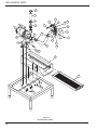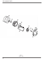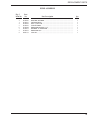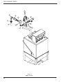
1
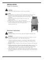
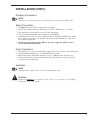
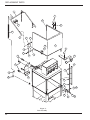
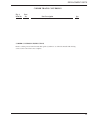
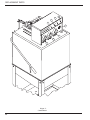
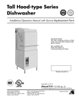
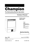
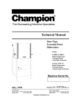
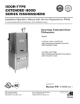
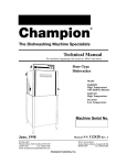
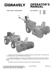
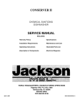
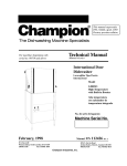
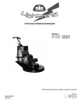
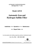
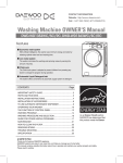
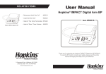
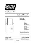
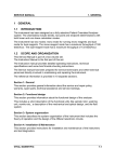
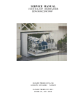
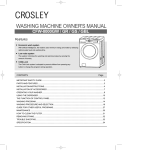
Technical Manual
Hood-Type
Dishwasher
Models Included:
VC1000
October, 2003
Valu-Clean Manual P/N
P.O. Box 4982
Winston-Salem, NC 27115
336/661-1559
Fax: 336/661-1979
113566 Rev. A
2674 N. Service Road
Jordan Station, Ontario, Canada L0R 1S0
905/562-6630
Fax: 905/562-5422
valu-clean.com
Complete the information below so it will be available for quick reference.
Model Number
Serial Number
Voltage and Phase
Valu-Clean Service Agency
Phone
Valu-Clean Parts Source
Phone
Valu-Clean (Canada)
National Service Department
Phone: 1 (905) 562-4195
Phone: 1 (336) 661-1559
1 (800) 263-5798
Fax:
1 (905) 562-4618
Valu-Clean (U.S.A.)
National Service Department
Fax: 1 (336) 661-1979
We strongly recommend that you Fax your orders.
NOTE: When calling to order parts, be sure to have the model number, serial number, voltage
of your machine.
Model and Serial number located
on the right side of the control cabinet.
COPYRIGHT © 2003 byValu-Clean
REVISION HISTORY
Revision History
Revision
Date
Revised
Pages
Serial Number
Effectivity
Comments
8/01/02
—
10/13/03
iii
—
Added new figure number
10/13/03
16-17
—
Added corner configuration instructions
First issue of manual and replacement parts
i
REVISION HISTORY
Revision History (Cont)
ii
TABLE OF CONTENTS
CONTENTS
Page
REVISION HISTORY...................................................................................................................... i
SAFETY SYMBOLS ...................................................................................................................... v
GENERAL SPECIFICATIONS ...................................................................................................... 1
INSTALLATION .............................................................................................................................. 2
Electrical Connections ........................................................................................................ 2
Water Connections .............................................................................................................. 3
Drain Connections .............................................................................................................. 3
Ventilation............................................................................................................................ 3
Chemical Connections ........................................................................................................ 4
INITIAL START-UP ........................................................................................................................ 5
OPERATION .................................................................................................................................... 5
DAILY CLEANING........................................................................................................................ 6
MAINTENANCE ............................................................................................................................ 7
TROUBLESHOOTING.................................................................................................................... 8
REPLACEMENT PARTS .............................................................................................................. 11
ELECTRICAL SCHEMATICS ...................................................................................................... 29
LIST OF FIGURES
Figure
Figure
Figure
Figure
Figure
Figure
Figure
Figure
1
2
3
4
5
6
7
8
—
—
—
—
—
—
—
—
Door Assembly ........................................................................................
Wash/Rinse Assembly ..............................................................................
Corner Conversion....................................................................................
Drain/Pump Assembly..............................................................................
Pump Assembly........................................................................................
Piping Assembly ......................................................................................
Control Panel............................................................................................
Control Cabinet ......................................................................................
12
14
16
18
20
22
24
26
iii
THIS PAGE
INTENTIONALLY
LEFT BLANK
iv
SAFETY SYMBOLS
Safety Symbols
•
The following symbols appear throughout this manual alerting you to potential
hazards. Statements associated with each symbol are printed in italics.
WARNING:
Warning statements indicate any condition or practice that
could result in personal injury or possible loss of life.
!
CAUTION:
Caution statements indicate any condition or practice which,
if not strictly observed or remedied, could result in damage
to or destruction of the equipment.
NOTE:
Note statements indicate any condition or practice which,
if observed, will help in the safe completion of a task.
General Safety Rules
•
The following general safety rules must be observed in addition to the specific cautions
and warnings presented in this manual.
•
Operators should use caution when loading and unloading wares from the equipment.
•
Operators must NOT bypass a safety interlock or control(s) to operate the dishwasher.
•
The service and maintenance instructions contained in this manual are intended for
qualified service personnel. These instructions assume that you are trained in basic electricity
and mechanical theory. If you are not a trained technician, then do not attempt to adjust or
repair the equipment as serious personal injury or damage to the equipment may result.
v
THIS PAGE
INTENTIONALLY
LEFT BLANK
vi
GENERAL SPECIFICATIONS
About this manual
All information, illustrations and specifications contained in this manual are based upon the latest
product information available at the time of publication. Valu-Clean constantly improves its products
and reserves the right to make changes at any time or to change specifications or design without notice
and without incurring any obligation.
Organization of Manual
This manual is divided into seven parts:
• General Specifications
• Installation
• Daily Operation
• Cleaning and Maintenance
• Troubleshooting
• Replacement Parts, contains parts diagrams and parts list.
• Electrical Schematics
NOTE:
Unless noted otherwise, dimensions, capacities, temperatures, etc., given in this manual are
U.S. Customary Measures and the Metric Equivalent of the U.S. customary measures.
Model
The VC1000 model is a low temperature (140˚F/60˚C ) sanitizing model for use with a hypochlorite
(Chlorine) based sanitizer at a minimum concentration of 50PPM or to your local codes, in the final
rinse. The dishwasher includes three chemical dispenser pumps located in the control cabinet on the
top of the machine.
Standard Equipment
•
Automatic Operation
•
Door safety switch
•
Common utility connections
•
Field convertible to corner model
•
Balanced door lift system
•
De-lime switch in control cabinet
•
Interchangeable upper and lower
spray arms
•
1-hp drip-proof pump motor
1
INSTALLATION
Unpack the dishwasher
!
CAUTION:
Care should be taken when lifting the machine to prevent damage.
1.
2.
3.
4.
NOTE:
The installation of your machine must meet all applicable health and safety codes.
Immediately after unpacking the machine, inspect for any shipping damage.
If damage is found, save the packing material and contact the carrier
immediately.
Remove the dishwasher from the skid. Move the machine to its
permanent location.
Machine must be placed on a sound self-draining floor.
Level the machine (if required) by placing a level on the top of the
machine and adjusting the feet. Level the machine from
front-back and side to side.
Electrical Connections
!
WARNING:
Electrical grounding connections must comply with all applicable Electrical Codes.
WARNING:
When working on the diswasher, disconnect the electric service and place a tag at the
disconnect switch to indicate work is being done on that circuit.
1. A qualified electrician must compare the electrical power supply with the machine
electrical specifications before connecting to the incoming service through a fused
disconnect switch.
2. The electrical supply is single phase. The machine must be installed on 15A single phase
breaker.
3. A knock out is provided at the left rear corner of the control cabinet (as viewed from the
front) for electrical service connection or connection will be made from the plug
(depending on how the machine was ordered). A fused disconnect switch or circuit
breaker (supplied by others) is required to protect the power supply circuit.
4. Single phase incoming wire connections are made at the machine’s main terminal block.
The main terminal block is located in the control cabinet on the back wall and to the left
side of cabinet.
2
INSTALLATION (CONT.)
Plumbing Connections
NOTE:
Plumbing connections must comply with all applicable sanitary and plumbing codes.
Water Connections
1.
2.
3.
4.
5.
VC1000 dishwashers require a single, hot water supply.
The hot water connection to the dishwasher is at the 1/2" NPT Female “Y” strainer.
The connection is made from the top rear of the dishwasher.
The recommended minimum water temperature is 140˚F/60˚C.
A manual shut-off valve for water (supplied by others) should be installed in the supply
line to allow for servicing of the machine. The shut-off valve should be the same size or
larger than the supply line.
6. Install a pressure reducing valve (PRV) in the water supply line if flow pressure
exceeds 20-22 PSI/138-151.8kPa.
Drain Connections
1.
2.
3.
4.
The dishwasher is a gravity drain machine equipped with 1-1/2" O.D. hose connection point.
The maximum drain flow rate is 15 gallons/min-56.8 liters/min.
Drain height for the dishwasher must not exceed 11" (280mm) above the floor level.
The drain connection is made to the dishwasher by connecting to the tail piece located
on the bottom of the drain pan.
Ventilation
NOTE:
Ventilation must comply with local sanitary and plumbing codes.
!
CAUTION:
Exhaust air should not be vented into a wall, ceiling, or concealed space of a building.
Condensation can cause damage.
3
INSTALLATION (CONT.)
Chemical Pumps
NOTE:
Consult a qualified chemical supplier for your chemical needs.
1. Prime switches are located on the right hand side of the control cabinet.
Peristaltic Pump
To prime the peristaltic pump:
1. Insert pump inlet hose into the detergent container.
2. Close machine door and turn power switch to “ON” position.
3. Allow wash tank to fill up then press detergent pump prime switch to prime inlet
and outlet hose.
4. Stop priming when detergent reaches machine.
4
INITIAL START-UP
Complete the installation
After the plumbing and electrical connections are made, follow the steps below to complete
the installation of your dishwasher.
1. Remove the protective covering from the exterior of the machine.
2. Remove any foreign material from the inside of the machine.
3. Make sure dishwasher power is off.
4. Turn the main water supply on.
5. Turn main power on at the main power service disconnect switch.
6. Install the pump suction filter.
7. Make sure that the overflow seats securely in the tank bottom.
8. Make sure doors are fully closed.
9. Turn power switch to the “ON” position.
10. Press and hold the fill switch until water overflows into the lower drain screen.
OPERATION
Operation and Use
1. Before washing make sure that:
• wall mounted on/off switch is switched on;
• water supply is open and water pressure is present;
• pump suction filter is installed in proper location;
• overflow tube is inserted in drain;
• rotating spray arms move freely;
• rinse, detergent and sanitizer containers are full;
2. Scrap and preflush all items to be washed. Load items into the rack.
Do not overload the rack. Wash only one layer of silverware in a rack.
3. Open the door and insert the rack into machine. Close door.
4. Machine starts automatically. CYCLE light glows green.
5. Remove rack when the CYCLE light goes out.
5
DAILY CLEANING
Cleaning your machine is the best maintenace that you can provide. Components that are not
regularly flushed and cleaned do not perform well. The following schedules are the minimum
requirements necessary for the proper performance of your machine. Intervals should be
shortened whenever your machine is faced with abnormal conditions, hard water or mutliple
shifts. Before carrying out the cleaning operations, turn off the main disconnect switch for the
equipment.
Cleaning Schedule
Every 2 Hours or After Each Meal Period
1. Press the drain switch and hold to drain wash tank. When all the water has drained, release
the switch.
2. Turn dishwasher and wall switch OFF.
3. Flush the interior with fresh water.
4. Remove scrap wash pump inlet screen. Rinse throughly to make sure that it is clean. Do not
bang or beat it on the side of sink or other hard objects as this will eventually cause it to
break or bend thus causing it to not fit or work properly.
5. Reinstall the pump scrap screen.
6. Clean spray arm nozzles as needed.
7. Remove scrap screen from bottom of the drain pan. Rinse throughly to remove all debris.
8. Replace scrap screen at the bottom of the drain pan.
Frequently check and clean the nozzles. Blocked nozzles will prevent the machine from cleaning
properly. To clean the wash/rinse arms:
1.
2.
3.
4.
5.
6.
Undo the thumbscrew which hold the arms in place.
Turn and remove the end caps.
Flush arms with water, use a toothpick or paperclip (if necessary) to clear the nozzles.
Do not beat the arms on anything to clean nozzles.
Replace end caps.
Replace arms back into machine.
Every 8 Hours or at the End of the Day
1.
2.
3.
4.
5.
Drain the machine and turn the power switch off..
Flush interior with fresh water.
Clean drain scrap screen and pump intake screen, as described above.
Clean spray arms and nozzles.
Throughly clean the exterior of the machine.
DO NOT HOSE DOWN WITH WATER.
6. Reassemble the machine.
7. Leave doors open to aid in drying the interior of machine.
!
6
CAUTION:
Do not leave water in wash tank overnight.
MAINTENANCE
Before carrying out any maintenance operations, turn off the main disconnect switch for the
equipment.
Do not use corrosive products such as sodium hypochlorite (bleach), acids, steel wool or steel
brushes to clean the inside and the outside of machine.
The presence of calcium and magnesium salt in water can compromise machine performance.
Ask a qualified chemical person to remove the deposits periodically.
Stainless steel surfaces should be cleaned well in order to avoid some oxidation risks, or
chemical reactions.
Deliming
Your dishwasher should be delimed regularly depending on the mineral content of your water.
Inspect the machine interior for mineral deposits and use a deliming solution for the best
cleaning results.
NOTE:
Consult your chemical supplier for an appropriate deliming solution.
!
WARNING:
Deliming soultions or other acids must not come in contact with household bleach (sodium
hypochlorite) or any chemicals containing chlorine, iodine, bromine, or fluorine. Mixing will
cause hazardous gases to form.
Skin contact with deliming solutions can cause severe iritation and possible chemical burns.
Consult your chemical supplier for specific safety precautions.
Deliming Process
1. Remove all dishes from machine.
2. Remove chemical pick-up tubes from their containers.
3. Place each tube in a container of fresh water and prime the chemical lines for several
minutes to throughly flush chemical from the lines. Leave the pick-up tubes out of their
containers.
4. Drain machine by holding the drain toggle switch until empty. Fill machine with water only
by the fill toggle switch. Run 1 cycle to rinse the inside of the machine then drain by holding
the drain toggle switch. Refill the machine by holding the fill toggle switch.
5. Spray interior walls with deliming solution and let sit for 5 to 10 minutes depending on the
amount of build-up. Add deliming solution to wash tank. Do not let chemicals sit for longer
than 15 minutes.
6. Close door, run on the automatic cycle.
7. Repeat steps 3-5 if necessary.
8. Repeat Step 4.
9. Refill the machine and run an additional cycle at least two more times. Drain and refill the
machine after each cycle to throughly flush any deliming solution from the interior of the
machine.
10. Flip the power switch to OFF. Leave doors open to aid in drying overnight. Deliming process
is now complete.
7
TROUBLESHOOTING
In order to find the cause of a breakdown or abnormal operating condition in your dishwasher
please ensure that:
1. All switches are ON
2. Drain overflow tube is in place and seated
3. Wash pipe and rinse nozzles are clean
4. Spray arms are in their proper positions
5. Pump inlet screen is properly positioned
6. Detergent, sanitizer and rinse additive dispensers are adequately filled
8. Doors are fully closed.
If a problem still exists, use the following table for troubleshooting
8
CONDITION
CAUSE
SOLUTION
Cycle will not start
Door not closed.................................. Make sure doors are fully closed
Door safety switch faulty .................. Contact your service agency
Main switch off.................................. Check disconnect
Low or no water
Main water supply is turned off ........
Drain/overflow tube is not
in place and seated ............................
............................................................
Faulty fill valve ..................................
Turn on house water supply
Clean, replace and seat drain tube
as needed.
Contact your chemcial supplier.
Continuous water filling
Fill valve will not close .................... Clean or replace
Any motor not running
Defective contactor ............................ Contact your chemical supplier
Defective motor ................................ Contact your chemical supplier
Wash tank water temperature
is low when in use
Incoming water temperature
at machine too low ............................ Raise temperature to 140˚F/60˚C
Defective thermometer ...................... Check or replace
Defective solenoid valve.................... Check or replace
Arms not rotating
Rinse nozzles not clean...................... Clean
Bearings worn .................................... Replace
Water supply pressure low ................ Check incoming water pressure
Insufficient pumped spray
pressure
Clogged pump intake screen..............
Clogged spray pipe ............................
Low water level in tank ....................
............................................................
Defective pump seal ..........................
Clean
Clean
Check drain and overflow tube, timer may
need adjustment, contact chemical supplier
Contact service agent
Insufficient rinse or no
rinse
Faulty pressure reducing valve ..........
Improper setting on pressure
reducing valve ....................................
Clogged rinse nozzle and/or pipe ......
Improper water line size ....................
Clean or replace
Set flow pressure to 20-22 psi [138-151 kPa]
Clean with paper clip/delime
Have installer change to proper size 1/2" NPT
TROUBLESHOOTING (CONT)
CONDITION
CAUSE
SOLUTION
Low final rinse temperature
Low incoming water .......................... Check valve to be sure it is clean and operating.
Defective thermometer ...................... Check for proper setting or replace
Machine leaking
Leaking at chemical hose ..................
Pump seal leaking ..............................
Leaking at pump hose........................
Leaking at doors ................................
Replace hoses
Replace seal
Contact your chemical supplier
Check to make sure that doors are fully closed
Water splashing out door
Nozzles/End caps missing ................
Wash nozzles blocked........................
Arms not rotating ..............................
Door handle twisted (pass through) ..
Replace caps
Clean
Replace bearings
Adjust or replace handle
Poor washing results
Detergent dispenser not
operating properly..............................
Insufficient detergents........................
Food Soil concentration too
high in wash tank ..............................
Wash water temperature
too low ..............................................
Contact detergent supplier
Contact detergent supplier
Prescrap dishes throughly
See condition “Wash Tank
Water Temperature” above
Wash arm clogged.............................. Clean
Improperly scraped dishes ................ Check scraping procedures
Ware improperly
placed in rack .................................... Use proper racks. Do not overload racks
Improperly cleaned
equipment .......................................... Unclog wash sprays and rinse nozzles
to maintain proper pressure and flow
conditions. Overflows must be open.
Keep wash water as clean as possible.
9
THIS PAGE
INTENTIONALLY
LEFT BLANK
10
REPLACEMENT PARTS
REPLACEMENT
PARTS
11
REPLACEMENT PARTS
1
5
25
2
6
3
4
13
10
20
9
14
10
15
7
8
11
13
12
21
22
23
16
Va
l
n
le a
u-C
24
17
18
19
26
24
27
27 28
28
29
27
30
Figure 1Door Assembly
12
28
REPLACEMENT PARTS
DOOR ASSEMBLY
Fig. 1
Item No.
Part
No.
1
2
3
4
5
6
7
8
9
10
11
12
13
14
15
16
17
18
19
20
21
22
23
24
25
26
27
28
29
30
0510458
0510456
0510459
0510460
107965
111439
W333052
0710488
107893
0509274
0510456
0310490
102376
W1554
0501539
0501501
0510492
100154
W333257
104883
111090
108954
W1539
0509439
0510457
0508665
0501478
107967
0501419
W1542
W15425
W1560
W1557
31
32
Part Description
DOOR HANDLE, VC1000 ......................................................................
DOOR HANDLE BUSHING ..................................................................
SPRING, DOOR VC1000 ........................................................................
GRIP, DOOR HANDLE ..........................................................................
NUT, GRIP 8-32 W/NYLON INSERT ....................................................
MAGNET, PERMANENT ......................................................................
DOOR, VC1000 WELD ASSY................................................................
DOOR STOP WELDMENT ....................................................................
SHOCK ABSORBER (NOT SHOWN) ..................................................
NUT, ACORN 5/16-18 SST ....................................................................
BUSHING, DOOR HANDLE..................................................................
WASHER, 0.313 X 1.00 16 GAUGE SST ..............................................
WASHER, FLAT 5/16 X 3/4 X 1/16........................................................
LINKAGE, DOOR HANDLE..................................................................
NUT, HEX 1/4-20 SST ............................................................................
LOCK WASHER 1/4" ..............................................................................
J BOLT, 5/16-18 UNC X 5" ....................................................................
NUT, PLAIN 5/16-18 ..............................................................................
SUPPORT, REAR HOSE/CABLE ..........................................................
SCREW, 6-32 X 3/8 ROUND HEAD......................................................
HAMLIN REED SWITCH ......................................................................
NUT, GRIP 6-32 W/NYLON INSERT ....................................................
WEARSTRIP, DOOR VC1000 ................................................................
SCREW, 10-32 X 1/4 HEX HEAD..........................................................
CLIP ON WEARSTRIP ..........................................................................
SCREW, 10-32 X 5/8 HEX WASHER HEAD ........................................
WASHER 17/64 ID X 9/16 OD 18GA ....................................................
NUT, GRIP 1/4-20 W/NYLON INSERT ................................................
BOLT, 1/4-20 X 1/2 HEX HEAD ............................................................
BRACKET, PILLAR RH SUPPORT ......................................................
BRACKET, PILLAR LH SUPPORT ......................................................
REMOVABLE TRACK GUIDE CORNER CONVERSION(NOT SHOWN)
TRACK WELDED ASSEMBLY (NOT SHOWN)..................................
Qty
1
4
1
2
2
1
1
2
2
4
4
2
4
2
4
4
2
4
1
2
1
2
2
8
2
2
8
2
4
1
1
A/R
A/R
13
REPLACEMENT PARTS
4
1
15
3
2
10
6
18
15
7
9
8
3
2
13
14
12
11
17
16
Figure 2wash/rinse assembly
14
REPLACEMENT PARTS
WASH/RINSE ASSMEBLY
Fig. 2
Item No.
Part
No.
1
2
3
4
5
6
7
8
9
10
11
12
13
14
15
16
17
18
19
20
W333242
0510420
0510495
0510484
0510483
100735
0501478
107440
0510512
0509989
201029
107967
0510489
0300823
0501395
113098
B501381
0510534
0510536
0510535
Part Description
WASH TUBE, 25MM SS VC1000 ..........................................................
SPRAYARM COMPLETE ......................................................................
SCREW, THUMB 5/16-18 ......................................................................
UPPER WASHARM HUB ......................................................................
LOWER WASHARM HUB ....................................................................
BOLT 1/4-20 X 5/8 HEX HEAD ............................................................
WASHER 17/64 ID X 9/16 OD 18GA ....................................................
THERMOMETER 8’ FLANGE ..............................................................
POLY NUT, 1/4 NPT ..............................................................................
ELBOW 1/4 TUBE X W1/4 MPT COMP POLY....................................
LOCKNUT 1/2" NP ................................................................................
NUT, GRIP 1/4-20 W/NYLON INSERT ................................................
GASKET, LOWER HUB ........................................................................
WASHER 9/32ID X 1"OD ......................................................................
SCREW SOCKET 1/4-20 X 5/16 ............................................................
FOOT INSERT ........................................................................................
RING, POSI GRIP LOCKING ................................................................
WASH ARM END CAP ..........................................................................
WASH ARM BEARING REBUILD KIT (NOT SHOWN) ....................
BEARING ASSEMBLY WASH ARM (NOT SHOWN) ........................
Qty
1
2
4
1
1
4
4
1
3
3
1
4
1
4
2
4
4
4
A/R
A/R
15
REPLACEMENT PARTS
1
A
Figure 3 Corner Track Conversion
16
REPLACEMENT PARTS
CORNER TRACKS CONVERSION
Fig. 2
Item No.
1
Part
No.
W1557
Part Description
Rack Slide VC1000, Assy ........................................................................
Qty
1
CORNER CONVERSION INSTRUCTIONS
Remove existing screws from front rack slide guide (a) and move to either side. Install with exisiting
screws. Corner conversion is now complete.
17
REPLACEMENT PARTS
12
13
4
12
6
3
7
11
21
22
20
2
8
10
5
14
1
23
A
17
24
9
15
25
16
19
18
B
A
Figure 4Drain/Pump Assembly
18
REPLACEMENT PARTS
DRAIN/PUMP ASSMEBLY
Fig. 4
Item No.
Part
No.
1
2
3
4
5
6
-7
8
9
10
11
12
13
14
15
16
17
18
19
20
21
22
23
24
25
26
27
0501412
0310479
0510417
107965
0310491
0710496
0510497
0508667
104165
SCREW, 10-32 X 3/8 TRUSS HEAD......................................................
COVER, SOLENOID ..............................................................................
SCREEN, PUMP INLET ........................................................................
NUT, GRIP 8-32 W/NYLON INSERT ....................................................
DRAIN STOPPER LIFT BRACKET ......................................................
ASSY, DRAIN BALL/OVERFLOW ......................................................
DRAIN BALL OVERFLOW TUBE........................................................
SCREW, RH 8-32 X 7/8 SS ....................................................................
CLAMP, HOSE M40................................................................................
1
1
1
1
1
1
A/R
1
2
0710474
0510421
0502571
0509235
0502665
100739
100826
0503679
W333009
W333002
0510400
0510493
0510494
0501423
0310477
0310478
0501406
107965
PUMP INLET HOSE NIPPLE ................................................................
PUMP DISCHARGE FITTING ..............................................................
HOSE CLAMP DISCHARGE ................................................................
HOSE, 1.25 ID X 1.625 OD BRAIDED PVC........................................
TUBING, 1/2" X 3/4" INNER BRAID....................................................
BOLT 5/16-18 X 3/4 HEX HEAD ..........................................................
WASHER, FLAT 5/16ID..........................................................................
CLAMP, SS GEAR TYPE 7/16 ..............................................................
FILTER BASKET/DRAIN SCREEN ......................................................
DRAIN PAN WELD ................................................................................
SOLENOID 120V 60HZ..........................................................................
BOLT, CARRIAGE 10-24 X 1/2 (FOR DRAIN SOLENOID) ..............
LOCKNUT, 10-24 W/NYLON INSERT ................................................
SCREW, RH 10-32 X 1-1/4 ....................................................................
SOLENOID LIFT STOP (GUIDE SOLENOID, SMALL) ....................
GUIDE, SOLENOID LIFT (LONG) ......................................................
SCREW, SLOT RH 8-32 X 1/2(NOT SHOWN) ....................................
NUT, GRIP 8-32 W/NYLON INSERT ....................................................
1
1
2
6ft
5ft
4
8
1
1
1
1
4
4
4
1
1
1
4
A
100739
100826
109009
BOLT 5/16-18 X 3/4 HEX HEAD ..........................................................
WASHER, FLAT 5/16ID..........................................................................
NUT, GRIP 5/16 W/NYLON INSERT ....................................................
4
8
4
B
107967
NUT, GRIP 1/4-20 W/NYLON INSERT ................................................
4
9
10
11
12
13
14
15
16
17
18
19
109578
0510421
108528
HOSE, DISCHARGE ..............................................................................
PUMP DICHARGE FITTING ................................................................
HOSE BARB 1/2 X 1/2
1
1
0509235
HOSE, 1.25ID X .620 OD BRAIDED ....................................................
A/R
W333009
FILTER BASKET/DRAIN SCREEN ......................................................
1
Part Description
Qty
19
REPLACEMENT PARTS
1
2
3
5
6
7
8
4
9
Figure 5Pump Assembly
20
REPLACEMENT PARTS
PUMP ASSMEBLY
Fig. 5
Item No.
Part
No.
1
2
3
4
5
6
7
8
9
0510525
0510526
0510527
0510529
0510528
0510530
0510531
0510532
0501533
Part Description
PUMP, MOTOR VC1000 ........................................................................
FLINGER, WASHER ..............................................................................
ADAPTER IRON ....................................................................................
SEAL 5/8 BN-CM....................................................................................
CASE GASKET ......................................................................................
IMPELLER BRONZE 3-7/8 ....................................................................
WASHER “P” IMPELLER ......................................................................
IMPELLER NUT ....................................................................................
VOLUTE ..................................................................................................
Qty
1
1
1
1
1
1
1
1
1
21
REPLACEMENT PARTS
11
10
9
3
4
12
5
5
2
1
15
6
7
8
5
14 13
n
le a
u-C
l
a
V
Figure 6Piping Assembly
22
REPLACEMENT PARTS
PIPING ASSEMBLY
Fig. 6
Item No.
Part
No.
1
2
3
4
5
6
7
8
9
10
11
12
13
14
15
0502665
0503679
108528
0510416
100209
113220
113221
0509938
109886
108516
109902
104421
0501539
0501501
0310422
Part Description
TUBING 1/2 X 3/4 INNER BRAID ........................................................
CLAMP, GEAR SST TYPE 7/16............................................................
HOSE BARB 1/2 X 1/2 90˚ ....................................................................
CHECK VALVE 1/2" ..............................................................................
NIPPLE, 1/2" CLOSE BRASS ..............................................................
VACUUM BREAKER BRASS 1/2"........................................................
REPAIR KIT 1/2" VACUUM BREAKER ..............................................
ELBOW, 1/2" FORGED 90˚ ....................................................................
VALVE, 1/2" ............................................................................................
COIL,VALVE ..........................................................................................
REPAIR KIT, VALVE 1/2" ......................................................................
LINE STRAINER 1/2" ............................................................................
NUT, PLAIN 1/4-20 ................................................................................
LOCKWASHER 1/4 ................................................................................
BRACKET, PLUMBING VC1000 ..........................................................
Qty
A/R
1
1
1
3
1
1
1
1
1
1
1
2
2
1
23
REPLACEMENT PARTS
2
3
4
5
1
u-C
l
a
V
n
le a
A
B
C
Figure 7Control Panel
24
REPLACEMENT PARTS
CONTROL PANEL
Fig. 7
Item No.
Part
No.
1
2
3
4
5
107440
0501398
0508551
0510399
B500394R
Part Description
THERMOMETER, FLANGE 8FT ..........................................................
TOGGLE SWITCH ON-OFF ..................................................................
LAMP , GREEN NEON 125VAC............................................................
TOGGLE SWITCH MOMENTARY VC1000 ........................................
LOCK, CABINET REWORKED ............................................................
Qty
1
1
1
1
1
CHEMICAL PUMPS
A
B
C
RINSE AID PUMP
109829
PUMP, PERISTALLIC ............................................................................
108194
TUBE 3/16ID X 3/8OD (INCLUDED IN 109829, NOT SHOWN) ......
0501518
TIE, NYLON ............................................................................................
0502666
TUBING, 1/8ID X 1/4OD PVC BEVERAGE ........................................
0306363
TUBE, STIFFNER 3/8 ID X 11-7/8 LONG (NOT SHOWN) ................
0501869
STRAINER (CHEMICAL BOTTLE)(NOT SHOWN) ..........................
0505483
LABEL RINSE AID ................................................................................
1
1
2
A/R
1
1
1
SANTIZING PUMP
109829
PUMP, PERISTALLIC ............................................................................
108194
TUBE 3/16ID X 3/8OD (INCLUDED IN 109829, NOT SHOWN) ......
0501518
TIE, NYLON ............................................................................................
0502666
TUBING, 1/8ID X 1/4OD PVC BEVERAGE ........................................
0306363
TUBE, STIFFNER 3/8 ID X 11-7/8 LONG (NOT SHOWN) ................
0501869
STRAINER (CHEMICAL BOTTLE)(NOT SHOWN) ..........................
0503694
LABEL SANITIZER................................................................................
1
1
2
A/R
1
1
1
DETERGENT PUMP
109829
PUMP, PERISTALLIC ............................................................................
108194
TUBE 3/16ID X 3/8OD (INCLUDED IN 109829, NOT SHOWN) ......
0501518
TIE, NYLON ............................................................................................
0502666
TUBING, 1/8ID X 1/4OD PVC BEVERAGE ........................................
0306363
TUBE, STIFFNER 3/8 ID X 11-7/8 LONG (NOT SHOWN) ................
0501869
STRAINER (CHEMICAL BOTTLE)(NOT SHOWN) ..........................
0503695
LABEL DETERGENT ............................................................................
1
1
2
A/R
1
1
1
25
REPLACEMENT PARTS
1
2
5
4
10
3
6
8
9
7
Figure 8Control Cabinet
26
REPLACEMENT PARTS
CONTROL CABINET
Fig. 8
Item No.
Part
No.
1
2
3
4
5
6
7
8
9
10
0510397
111068
111036
0501373
0509296
107369
0503757
108299
107440
0510399
Part Description
TIMER ASSEMBLY ................................................................................
RELAY 120VAC 2PDT............................................................................
SOCKET, RELAY ....................................................................................
TOGGLE SWITCH ..................................................................................
COUNTER, 120VAC NON-RESET ........................................................
CONTACTOR, 2POLE 120V ..................................................................
MOTOR, PUMP DRIVE..........................................................................
MOTOR REDUCER 35RPM ..................................................................
THERMOMETER, FLANGE 8FT ........................................................
TOGGLE SWITCCH ..............................................................................
Qty
1
1
1
1
1
1
1
2
1
3
27
THIS PAGE
INTENTIONALLY
LEFT BLANK
28
ELECTRICAL
SCHEMATICS
29