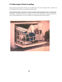
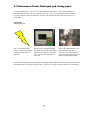
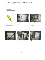
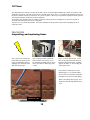
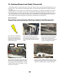
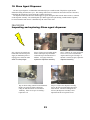
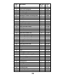
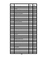
1
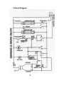
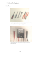
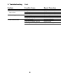
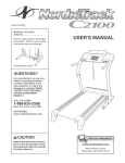
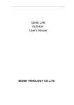
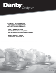
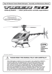
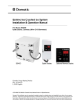
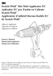
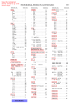
SERVICE MANUAL
COUNTER-TOP DISHWASHER
DDW398W,DDW399W
DANBY PRODUCTS LTD.
GUELPH, ONTARIO N1H6Z9
DANBY PRODUCTS INC.
FINDLAY, OH 45839
Contents
1. Circuit Diagram___________________________________________1
2. Tools and Test Equipment___________________________________2
3. Troubleshooting___________________________________________3
4. Performance Check: Loading_________________________________5
5. Performance Check: Detergent and Rinse Agent__________________7
6. Power Connections_________________________________________8
7. Removing Outer Casing and Control Panel______________________9
8. Inner Wiring Connections Check______________________________10
9. Door Latch Mechanical_____________________________________11
10. Timer___________________________________________________12
11. Power Switch and Option Switch_____________________________15
12. Water Inlet Valve_________________________________________16
13. Pressure Switches_________________________________________18
14. Pump and Motor Assembly__________________________________19
15. Heating Element and Safety Thermostat________________________20
16. Normal Thermostat________________________________________21
17. Hose Connector___________________________________________22
18. Rinse Agent Dispenser______________________________________23
19. Parts List_________________________________________________24
20. Exploded View____________________________________________29
1.Circuit Diagram
1.
2. Tools and Test Equipment
Hand Tools
A basic compliment of hand tools i.e. flat and phillips head screw drivers,
socket set, pliers and wire striper / crimping tool.
A basic volt ohm meter (VOM) will also be required for circuit and
component testing.
2
3. Troubleshooting
Problem
Possible Cause
Repair Procedure
1.Pump and timer do not run
(power pilot is not illuminated)
Power receptacle defective
Power cord defective
Open wire to timer
Open door latch switch
Power switch defective
Kinked fill hose
Low houes water pressure
Blocked inlet valve or faucet
Open or defective pressure switch
Pressure switch defective
water inlet valve stuck open
Pressure switch defective
Check receptacle
Check power cord
Check timer
Check wiring and connection
Check option switch and power switch
Check inlet hose
check faucet
Check inlet valve and faucet
See pressure switch
See pressure switch
See inlet valve
See pressure switch
Poor terminal connection on timer
Defective timer
Drain hose kinked or blocked
Resistance or capacitance defect
Dishwasher not level
Door not closing tightly
Crack in hose connection
Gasket damaged
Inlet valve connector loose or defective
Loose connection between pump & sump
Pump body damaged
Pump seal defective
Detergent is old and caked
See timer
See timer
Check drain hose
See pump and motor assembly
Adjust leveling legs
Adjust latch strike
Replace hose
Replace gasket
Check water inlet valve
Reconnect using encapsulant
Replace pump and motor assembly
See pump and motor assembly
See detergent and rinse agent
Dishes block water from detergent cup
No or low water
No rinse agent in dispenser
Solenoid inoperative
Open timer contacts
Dispenser gasket defective
Dispenser tank cracked
Improper loading
Detergent old, incorrect type or amount
Improper cycle selection
Kinked or cloged drain hose
Foreign material in wash system
Foreign material in spray arm
Rinse agent leaks into tub during wash
Rinse agent not used
heating unit inoperative
See loading dishes
See #2
Check rinse agent level
check rinse agent dispenser
Check timer
Replace gasket
Replace dispenser
See loading dishes
See detergent and rinse agent
Choose proper cycle
Check drain hose
Check wash system
Clean wash arm
Replace dispenser
Fill rinse agent dispenser
See heating element
2. Too little or no water fill
3. Water does not shut off
4. Water pumping out before
washing dishes.
5. Timer does not advance
6. Water does not pump out
7. Dishwasher leaks
8. Detergent remains in detergent
cup
9. Rinse agent dispenser does not
release rinse agent
10. Rinse agent dispenser leaks
11. Poor washing results
12. Poor drying
3
3. Troubleshooting
Cont.
Problem
Possible Cause
Repair Procedure
13. Condensation on door
14. Dishwasher door is difficult to
open or close
Some condensation is normal
Door gasket emersion
Door linkage bent
Door hook deflection
Dishes rattling
Drain pump viberating
Foreign object in pump
Silcon sleeve worn
Connector hose washer defective
Connector gasket damaged
Cause- steam vent on door
Pull gasket into slot
See door latch assembly
See door latch assembly
See loading dishes
See pump and motor assembly
Check wash pump
See hose connectors
Replace washer
Replace connector gasket
15. Noise during operation
16. Hose connector leaks
4
4. Performance Check: Loading
Many performance problems that commonly occur in dishwashers are not due to mechanical defects. Problems with
poor washing results can often be resolved without making repairs.
The procedures in this manual are designed to help you eliminate performance problems before you begin checking
and testing the dishwasher’s components. To get the best results from the dishwasher it is necessary to form good
loading habits. If the dishwasher seem to be running correctly, but does not get the dishes really clean, check to be
sure it is being loaded properly. The owner’s manual gives detailed instructions on this procedure.
5
PROCEDURE
Loading dishwasher
6
5. Performance Check: Detergent and rinsing agent
Water and detergent are major factors for good dishwasher performance. Water pressure, hardness
and temperature also play vital roles in getting good results. The correct detergent, in proper amounts,
is equally important. The water hardness in your area will effect the amount of detergent needed to get
clean dishes.
PROCEDURE
Checking detergent
Step 1: For personal safety
always exercise caution when
working with any electrical
appliance..
Step 2: Only use detergent intended
specifically for automatic dishwashers.
Make sure the detergent is fresh and
dry. Old, caked detergent will not
wash well.
Step 3: This dishwasher has a rinse
agent dispenser, make sure it is
filled. The rinse agent makes the
water flow off the dishes faster, this
reduces spotting and aids drying.
NOTE: Check with the local water company concerning the water conditions in your area. With very hard water
more detergent may be required for good results. If you have soft water or a water softener, use less detergent.
7
6. Power Connections
Dishwashers plug into standard 120 volt wall receptacles with a three pronged (grounded) plug. If the dishwasher
fails to operate properly, the power cord may be preventing power from reaching the unit.
Most problems associated with the power cord or connection are caused by damage and/or loose connections
and will likely be visible.
CAUTION: To minimize the possibility of electric shock, be certain that the wall receptacle and circuit
are properly grounded before using the dishwasher. Use of a plug adapter to adapt to a two prong outlet is
NOT recommended. Under no circumstances should you attempt to cut off or otherwise remove the third
prong (ground prong) from the power cord..
PROCEDURE
Inspecting: Power Connections
Step 1: Be sure all dishwasher
Controls are turned off
Step 2: Inspect power cord at
connection to receptacle. Improper
connection could be the sole cause
of trouble.
Step 4: Inspect plug carefully for
Damaged, corroded or loose terminals.
Look for signs of overheating around
the molded portion. If plug is damaged
replace the power cord.
Step 3: Pull plug from receptacle with
a firm quick tug. Always grasp the
plug, never pull the cord. Be careful
Not to contact the blades of plug.
Step 5: To replace cord, disconnect remove
mounting screws on power cord strain relief .
Disconnect internal connections and install
new cord same as original. Reassemble
dishwasher and check operation.
8
7. Removing Outer Casing And Control Panel
PROCEDURE
Removing outer case
Step 1: For your personal safety
exercise caution when working with
any electrical appliance.
Step 2:Remove stainless--steel screws
on both sides of outer casing.
Step 4: Remove casing screws on
rear of unit
Step 5: Lift casing straight off
9
Step 3:Open door and remove six
Screws on left and top edges of
inner liner.
Step 6: Remove six screws fastening
front control cover.
8. Inner Wiring Connections Check
Power is carried to the components of the dishwasher by a network of insulated wires. These wires are connected to
the timer, switches and other dishwasher components by means of push-on connectors.
It is very important that the wiring be free of any damage. Any cut that reduces the diameter of the wire reduces
the amount of power it will carry. Also, the wire may overheat and eventually break at that point. If the terminals
become dull and oxidized they should be replaced.
Whenever servicing the wiring harness be sure to note the of any green and / or yellow/brown ground wires in the
area in which you are working. Be certain all are properly connected upon completion of service. This is vital to
avoid danger of shock or short circuit.
CAUTION:
CAUTION If replacement wire is required, use only appliance wire having the same temperature and guage rating
as the wire you are replacing. This information is usually printed on the wire itself.
PROCEDURE
Repairing wiring and connections
Step 1: Be sure all controls are
turned OFF. Disconnect power
supply at distribution panel or
unplug power cord from outlet.
Watch for sharp edges.
Step 2: This procedure requires the
removal of the outer casing. If you
are unfamiliar with this process, please
refer to procedure #7:Removing outer
Casing.
10
Step 3: Inspect all push-on terminals
and inner connecting wiring for signs
of damage. i.e. burnt, pinched, loose or
frayed.
9. Door Latch
The door latch is essential to the operation of the dishwasher. Latching the door closes a switch allowing electrical
current to flow to the timer. The timer controls all other components.
If the door latch switch is open, the dishwasher will not operate. The latch switch cannot be activated while the door
is open. This safety mechanism prevents the dishwasher from being operated when the door is open. However, if the
door latch switch contacts become stuck in the closed position, the dishwasher will not stop when door is opened during
the cycle.
PROCEDURE
Door Latch Switch Replacement
Step 1: Always unplug from
receptacle before repairing.
Step 2: Remove outer casing.
Step 4: Install new microswitch and
connect same as original installation.
11
Step 3: Check for defects in microswitch or connections. If switch is bad
remove the two mounting screws.
Disconnect and replace switch.
10.Timer
The dishwasher timer consists of a timer motor and a variety of switches that automatically controls every phase of the
dishwashers operation. The timer motor runs at a constant speed, like a clock. As it advances through the selected cycle,
the timer’s internal switches open and close in a precise sequence. When a preset period has elapsed, the timer opens the
switch again and shuts off the power to that component.
All outgoing wires from the timer are number-coded. By referring to the circuit diagram, you can trace the path of
electrical current from the timer to any component.
The timer is a very reliable mechanism. It is best to eliminate all other possible causes before attempting to test or
replace the timer.
PROCEDURE
Inspecting and replacing timer
Step 1: Be sure all controls are
turned OFF. Disconnect power
supply at distribution panel or
unplug power cord from outlet.
Watch for sharp edges.
Step 2: This procedure requires the
removal of the outer casing. If you
are unfamiliar with this process, please
refer to procedure #7:Removing outer
Casing.
Step 3: To check timer motor, set the
timer to the off position and check for
continuity through the motor windings
(approx. 2k ohms). If the windings are
open replace timer.
Step 4:Refer to dishwasher’s circuit
Diagram page 1 to see which contacts
close to activate a particular component.
(Example:4 to 4a close for drain pump)
Refer to the timing chart on page 14 to
determine when the individual contacts
close .
FRONT OF UNIT
12
PROCEDURE
Inspecting and replacing timer (Continued)
Step 5:Remove the leads from the
Terminals to be checked. Using an
ohm meter, check the resistance
through the contact while turning the
timer. If the contacts being checked
do not close at the appropriate times
during the cycle, replace the timer
.
Step 8: Remount new timer
Step 6:To remove the timer, remove
the two timer mounting screws.
Step 9: Reassemble dishwasher, apply
power and test operation.
13
Step 7:Move leads terminal for
terminal to the new timer.
Timer : Cam Timing Chart
14
11. Power switch and option switch
When you press the power switch on, and the dishwasher remains dead with no power light this may be a
malfunction of the power switch.
When you press the option switch and the heating element can not be energized and the Sani/Econo light does
not come on, this may be a malfunction of the option switch.
PROCEDURE
Inspecting / replacing : power switch and option switch
Step 1: Be sure all controls are
turned OFF. Disconnect power
supply at distribution panel or
unplug power cord from outlet.
watch for sharp edges.
Step 2: This procedure requires the
removal of the outer casing. If you
are unfamiliar with this process, please
refer to procedure #7:Removing outer
casing..
Step 4: If the switch is defective,
replace the switch and reconnect
same as original installation.
15
Step 3: Using a ohm meter, check for
bad contacts in the power or option
switches.
12.Water inlet valve
The water inlet valve controls the flow of water into the dishwasher. A solenoid coil attached to the valve housing
creates a magnetic field when energized. This magnetic field pulls open a plunger inside the valve allowing the water
to flow through and into the dishwasher.
The water fill is controlled by the timer, which opens the valve for a predetermined amount of time
Under normal conditions the tub should fill to approximately 85mm. or 3.5in. from the bottom of the sump. Open
the dishwasher after any fill cycle to check for normal water level.
A malfunctioning water inlet valve solenoid may only allow the dishwasher to fill intermittently. In this case no
water will enter the dishwasher during the rinse cycle. This problem can best be diagnosed by operating the dishwasher
and listing for the water entering during each fill cycle.
PROCEDURE
Inspecting and replacing : Water inlet valve
Step 1: Be sure all controls are
turned OFF. Disconnect power
supply at distribution panel or
unplug power cord from outlet.
watch for sharp edges.
Step 4: If water fill is less than
normal,detach fill hose to expose
filter screen. Clean or replace as
necessary.
Step 2: This procedure requires the
removal of the outer casing. If you
are unfamiliar with this process, please.
refer to procedure #7:Removing outer
casing..
Step 5: Using a ohm meter check for
continuity through the solenoid. If
solenoid winding is open, replace
valve.
16
Step 3: Locate valve where inlet hose
is attached. Check wires and valve
body.
Step 6: To replace water valve,
shut off water supply and disconnect
faucet coupling.
PROCEDURE
Inspecting and replacing: Water inlet valve (continued)
Step 7: Disconnect incomming water
Water supply hose. Remove clamp
and detach smaller hose running into
dishwasher tub.
Step 8: Remove mounting screw that
secures fill valve to rear panel. Install
new valve and reconnect leads and
water lines. Reassemble dishwasher
and reconnect water and power supply.
NOTE: If water continues to fill, even when power is disconnected, this is caused by damage to, or sediments
in valve housing or bellows. In either case entire valve should be replaced.
NOTE: If open winding in solenoid were proceeded by continuous filling and draining. Make sure timer is
Advancing through the fill cycle. Continuous duty will burn out water valve solenoid.
17
13. Pressure Switches
There are two pressure switches on the dishwasher. One is for controlling normal water level set at approx. 85mm
or 3.5 inches of water in sump. This will be referred to as the Normal Pressure Switch. The other one is for
preventing overflow and is set for approx. 102mm or 4 inches of water in sump. This one will be referred to as the
Safety Pressure Switch. If the water in the tank rises above the pre-set level, the safety pressure switch opens the
Circuit and stops power to the fill valve and closes the circuit to the drain pump, expelling excess water.
The safety pressure switch shuts water off only in cases of electrical malfunction. If a mechanical defect or foreign
object causes the inlet valve to stick open, the safety pressure switch will not be able to stop the overflow.
The safety pressure switch should never cut off the water inlet valve solenoid during normal fill, if it does it is not
properly adjusted.
PROCEDURE
Inspecting and replacing: Pressure switch
Step 1: Be sure all controls are
turned OFF. Disconnect power
supply at distribution panel or
unplug power cord from outlet.
watch for sharp edges.
Step 2: This procedure requires the
removal of the outer casing. If you
are unfamiliar with this process, please.
refer to procedure #7:Removing outer
casing..
Step 4: If the water level is incorrect
Check the pressure switch connecting
hoses and all connections to see if
there is air leakage and pressure loss.
Reseal any loose connections.
Step 5: If a pressure switch is bad
remove mounting screw and replace
switch.
18
Step 3: Hold a ruler vertically in the
sump, the tub should fill between
81-87mm or 3.25 to3.5 inches.
Step 6: Pressure switches must be
adjusted with a special screwdriver
to the proper level (step 3).
After adjustment is complete a drop
of glue should be placed on the
Threads to prevent further movement
14. Pump and Motor Assembly
The circulation pump and drain pump are combined and driven by the same reversing motor. The timer
activates the circulation winding during wash and the drain winding during pumpout with pauses between
changes in direction.
PROCEDURE
Inspecting and replacing: Pump and motor assembly
Step 1: Be sure all controls are
turned OFF. Disconnect power
supply at distribution panel or
unplug power cord from outlet.
watch for sharp edges.
Step 4: Turn dishwasher up side
down. Remove 4 motor mounting
and bracket mounting screws.
Release wire clips and remove
bottom panal.
Step 2: This procedure requires the
removal of the outer casing. If you
are unfamiliar with this process, please
refer to procedure #7:Removing outer
casing..
Step 5: Using a ohm meter, check
the pump motor windings.
Wash winding = blue lead on resistor
Drain winding = #14 on safety
pressure switch.
Common = black lead on fill valve.
19
Step 3: Unclip and remove washarm.
Unthread and remove washarm base
nut.
Step 6: If defective, release hose
camps and replace pump and motor
assembly.
15. Heating Element and Safety Thermostat
The heating element is located at the bottom of the sump. When the unit is energized during the heated wash cycle ,
it heats the water. The warmed air rises through the sump cover into the tub providing efficient washing and drying
of the dishes.
An inner resistance coil of nichrome wire, which does the actual heating, is completely surrounded by an electrical
insulation material. This assembly is protected by a metal sheath to help reduce damage and oxidation. Since you
can’t see the internal coil, in most cases you will have to rely on the ohm meter to determine the condition of the coil.
The safety thermostat acts as a temperature limit switch. If a malfunction causes the temperature rises above the
Limit of the thermostat, the heating element is disabled preventing damage to the dishwasher.
PROCEDURE
Inspecting and replacing: Heating element and thermostat
Step 1: Be sure all controls are
turned OFF. Disconnect power
supply at distribution panel or
unplug power cord from outlet.
watch for sharp edges.
Element
Step 2: This procedure requires the
removal of the outer casing. If you
are unfamiliar with this process, please.
refer to procedure #7:Removing outer
casing..
Step 3: The heater and thermostat are
located on the left side of the dishwasher in the end of the sump.
remove wires and inspect visually for
burned or damaged connections.
Thermostat
Step 4: Using an ohm meter, remove the wires
And check for continuity through the element
And safety thermostat independently. If either
component checks open,“no reading”, it is bad
and needs to be replaced.
Step 5: To replace either componant, remove the two
mounting nuts using a 8mm or 11/32 deepwell scocket.
Install new component and re assemble dishwasher.
20
16. Normal Thermostat
The normal thermostat is used to control the water temperature during the wash and final rinse when the sani
option is selected. When the sani option is selected, the timer stops at specific points in the cycle and the heating
element is energized. When the water temperature reaches 154 F or 67.7C the thermostat contacts close and the
timer continues through the cycle. The extra water heating period assures temperatures high enough to produce
good wash results.
PROCEDURE
Inspecting and replacing: Normal Thermostat
Normal thermostat
Step 1: Be sure all controls are
turned OFF. Disconnect power
supply at distribution panel or
unplug power cord from outlet.
watch for sharp edges.
Step 2: This procedure requires the
removal of the outer casing. If you
are unfamiliar with this process, please.
refer to procedure #7:Removing outer
casing.
Step 4: Using an ohm meter remove the wires
and check for continuity across the thermostat
terminals. These contacts should always be
open at room temperature so if there is any
reading at all the thermostat must be replaced
.
Step 3: The normal thermostat can be
accessed from the left side of the dishwasher and is on the back of the sump.
Step 5: To replace the normal thermostat
remove the two mounting screws and install
the new component.
Reassemble dishwasher and check operation.
21
17. Hose Connector
The hose assembly is made up of a water inlet hose, a drain hose and a hose connector. The hose connector
fastens to the kitchen faucet by means of a faucet adapter. The hose connector also has a pressure relief button to
relieve pressure before disconnecting and allows water to be used in the sink while the dishwasher is operating.
PROCEDURE
Inspecting and replacing: Hose Connector
Step 1: Be sure all controls are
turned OFF. Disconnect power
supply at distribution panel or
unplug power cord from outlet.
watch for sharp edges.
Step 2:Inspect hoses for cracking or
deterioration. Disconnect and replace
as necessary.
Step 4: Replace washers in all
Leaking hose connections.
Reassemble dishwasher and
Check operation.
22
Step 3: Any leaks in the connector
are resolved by replacing the hose
connector as an assembly.
18. Rinse Agent Dispenser
The rinse agent dispenser on dishwashers automatically inject a small amount of liquid rinse agent into the
dishwasher during the final rinse cycle. This wetting solution acts to break down the surface tension of the water,
minimizing the formation of spots and streaks on dishes and glasses.
The dispenser tank holds about one month supply of agent. During the final rinse the timer activates a solenoid
on the dispenser assembly. The solenoid pulls up a rubber tipped valve pin allowing a small amount of agent to
be released into the tank where it is distributed by the action of the water.
PROCEDURE
Inspecting and replacing: Rinse agent dispenser
Step 1: Be sure all controls are
turned OFF. Disconnect power
supply at distribution panel or
unplug power cord from outlet.
watch for sharp edges.
Step 2: If rinse agent is leaking inside,
remove and inspect cap and washer.
reassemble wipe off tank and wait 5
Minutes. If seepage still shows
replace the dispenser assembly.
Step 4: Check wiring connections and terminals.
Replace or repair any faulty connections.
Using an ohm meter check for solenoid for
continuity. If the coil is open “no reading “
replace the coil.
23
Step 3: Remove six screws and small
access cover on rear of dishwasher.
Inspect tank for signs of leakage. If
the tank is cracked or split, replace the
dispenser assembly.
Step 5: To remove the dispenser assembly,
remove the fill cap and mounting nuts from
inside the tub. after the mounting nuts are
removed, the dispenser assembly con be
replaced from the access panel on rear.
Ilus
No.
1
2
3
4
5
6
7
8
9
10
11
12
13
14
15
16
17
18
19
20
21
22
23
24
25
26
27
28
29
30
31
32
33
34
35
36
37
38
39
40
41
Description
Door Spring
Front Cover Facing Bar
Filter Assembly
Outer Casing
Outer Casing Screw
Absorbtion Proofed Connecting Hose
Clamp 24
Name Plate
Inlet Hose
Clamp 16
Spray Arm Assembly
Spray Arm Base Screw
Spray Arm Base Gasket
Front Cover
Bottom Pan
Foot
Motor Base Rubber Pad
Washer
Pressure Switch Bracing Bar
Pressure Switch (normal)
Pressure Switch (safety)
Clamp 24
Clamp 26
Drain pump Drain Hose
Clamp 45.1
Clip
Nut
Sump
Heating Element
Heating Element Gasket
Heating Element Mounting Plate
Thermostat #1
Thermostat #1 Clamp
Sump Gasket
Thermostat #2
Sump Tap
Clamp 26
Drain pump Inlet Hose
Circulation Hose
Clamp 41.5
Pressure Switch Connecting Hose
24
Qty Per
Unit
1
1
1
2
1
1
3
1
1
2
1
1
1
1
1
5
4
4
1
1
1
1
1
1
1
7
5
1
1
1
1
1
1
1
1
1
1
1
1
1
1
Part
No.
1.398
2.398
3.398
4.398
5.398
6.398
7.398
8.398
9.398
10.398
11.398
12.398
13.398
14.398
15.398
16.398
17.398
18.398
19.398
20.398
21.398
22.398
23.398
24.398
25.398
26.398
27.398
28.398
29.398
30.398
31.398
32.398
33.398
34.398
35.398
36.398
37.398
38.398
39.398
40.398
41.398
Ilus
No.
42
43
44
45
46
47
48
49
50
51
52
53
54
55
56
57
58
59
60
61
62
63
64
65
66
67
68
69
70
71
72
73
74
75
76
77
78
79
80
81
82
Description
Pressure Switch Connector
Pressure Switch Connector Hose
Clamp 22
Thermostat #2 Gasket
Pressure Switch Connector Hose #2
Spray arm hose
Circulation outlet gasket
Circulation pump
Circulation wheel
Diaphragm
Drain wheel
Motor axial gasket
Pump gasket
Drain pump assembly
Motor bracing bar
Resistor
Capacitor
Motor
Fan
Outer door assembly
Door left hinge
Pulley
Pulley axial
Door bracing bar
Inner door
Door hook
Ventilation window gasket
Ventilation window
Ventilation window cover
Door right hinge
Door gasket 1
Inner container assembly
Door gasket 2
Front left bracing bar
Screw
Screw gasket
Left rear bracing bar
Top rubber plate
Inlet connector 1
Inlet connector 2
Inlet connector gasket
25
Qty Per
Unit
1
1
2
1
1
1
2
1
1
1
1
1
1
1
1
1
1
1
1
1
1
2
2
1
1
1
1
1
1
1
1
1
1
1
6
6
1
1
1
1
2
Part
No.
42.398
43.398
44.398
45.398
46.398
47.398
48.398
49.398
50.398
51.398
52.398
53.398
54.398
55.398
56.398
57.398
58.398
59.398
60.398
61.398
62.398
63.398
64.398
65.398
66.398
67.398
68.398
69.398
70.398
71.398
72.398
73.398
74.398
75.398
76.398
77.398
78.398
79.398
80.398
81.398
82.398
Ilus
No.
83
84
85
86
87
88
89
90
91
92
93
94
95
96
97
98
99
100
101
102
103
104
105
106
107
108
109
110
111
112
113
114
115
116
117
118
119
120
121
122
123
Description
Right rear bracing bar
Dispenser gasket
Dispenser solenoid
Dispenser cover #1
Dispenser mounting screw
Dispenser cover #2
Dispenser body assembly
Door lock holder
Slider
Door lock spring #1
Spring #1 washer
Door lock screw
Door lock base
Qty Per
Unit
1
2
1
1
1
1
1
1
1
1
1
2
1
Part
No.
83.398
84.398
85.398
86.398
87.398
88.398
89.398
90.398
91.398
92.398
93.398
94.398
95.398
Insulation piece
Door lock spring #2
Linkage
Microswitch
Right front bracing bar
Wobbler
Wobbler spring
Axis
Forel ring
Rear panel
Power cord clamp
Insulation porcelain
Lug
Inlet valve
Inlet valve mounting plate
Drain hose connector
Power cord
Power cord pad
Turn knob
Switch button
Control panel
Door button
Pilot cover
Control panel bracing bar
Tumbling rod hinge
Tumbling rod hinge
Pilot holder
1
1
1
1
1
1
1
1
1
1
1
1
2
1
1
1
1
1
1
2
1
1
2
1
1
1
1
97.398
98.398
99.398
100.398
101.398
102.398
103.398
104.398
105.398
106.398
107.398
108.398
109.398
110.398
111.398
112.398
113.398
114.398
115.398
116.398
117.398
118.398
119.398
120.398
121.398
122.398
123.398
26
Ilus
No.
124
125
126
127
128
129
130
131
132
133
134
135
136
137
138
139
140
141
142
143
144
145
146
147
148
149
150
151
152
Description
Pilot
Power switch
Option switch
Timer
Door lock button spring
Cross recessed pan head
Tapping screw
Cross recessed big pan head
Tapping screw
Cross recessed big pan head
Tapping screw
Cross recessed big pan head
Tapping screw
Cross recessed pan head
Thread forming screw
Cross recessed pan head
Tapping screw
Grounging screw
Spring washer
Inside swath locking washer
Plain washer #4
Hexagon nut
Cross recessed pan head
Tapping screw
Cross recessed pan head
Tapping screw
Open baffle
Cross recessed pan head thread
Forming screw
Plain washer #5
Cross recessed pan head screw
Cross recessed pan head screw
Cross recessed countersunk head
screw
Cross recessed pan head
Tapping screw
Cross recessed pan countersunk head
Tapping screw
Hexagon nut M5
Hexagon nut M12 X 1.5
Hexagon nut M16 X 1.5
27
Qty Per
Unit
2
1
1
1
1
45
Part
No.
124.398
125.398
126.398
127.398
128.398
129.398
10
130.398
8
131.398
8
132.398
4
133.398
3
134.398
5
7
5
5
3
2
135.398
136.398
137.398
138.398
139.398
140.398
5
141.398
1
3
142.398
143.398
3
4
2
4
144.398
145.398
146.398
147.398
4
148.398
4
149.398
8
1
1
150.398
151.398
152.398
Ilus
No.
153
154
155
156
157
158
159
160
161
162
163
164
165
166
167
168
169
170
171
172
173
174
175
176
177
178
179
180
181
182
Description
Cross recessed pan head tapping screw
Cross recessed pan head tapping screw
Cross recessed pan head tapping screw
Cross recessed pan head tapping screw
Cross recessed pan head screw
Cross recessed pan head forming screw
Cross recessed pan head tapping screw
Cross recessed pan head screw
Connecting wire
Instruction manual
Service manual
QC passed sticker
Plastic bag
Inlet hose assembly
Drain hose assembly
Packing pad #1
Packing pad #2
Packing pad #3
Packing pad #4
Hose holder
Wire basket
Cup rack
Basket wheel
Wheel axis
Silverware basket
Quick connector assembly
Condenser nut
Condenser gasket
Condenser
Small rear cover
28
Qty Per
Unit
2
2
2
3
2
1
2
4
1
1
1
1
3
1
1
1
1
1
1
1
1
1
1
1
1
1
1
1
1
1
Part
No.
153.398
154.398
155.398
156.398
157.398
158.398
159.398
160.398
161.398
162.398
163.398
164.398
165.398
166.398
167.398
168.398
169.398
170.398
171.398
172.398
173.398
174.398
175.398
176.398
177.398
178.398
179.398
180.398
181.398
182.398
29
30
31
32
33
34
35
36
37
38