1
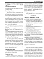
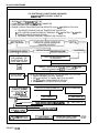
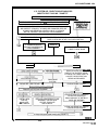
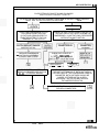
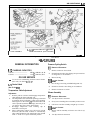
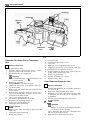
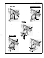
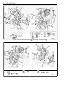
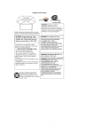
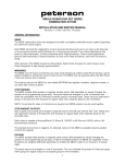
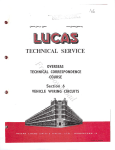
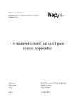
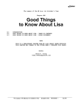
AIR CONDITIONING 1B-1
SECTION 1B
AIR CONDITIONING
When performing air conditioning diagnosis on
vehicles equipped with a catalytic converter, it will be
necessary to W A R M the engine to a NORMAL operating
temperature BEFORE attempting to idle the engine for
periods greater than five (5) minutes. Once the engine
attains normal idle, diagnosis and adjustments can be made.
CONTENTS
General Description ............................................
Diagnosis ................................................................
Service Procedures .............................................
General Information A Series ..........................
On-Car Service A Series ....................................
General Information J Series ..........................
On-Car Service J Series ....................................
B- 1
B-3
B-7
B-17
B-17
B-35
B-35
Also see Section 6B - Cooling System for r lated
information, diagnosis and art.
GENERAL DESCRIPTION
The Cycling Clutch Orifice Tube (C.C.O.T.)
refrigeration system is designed to cycle a compressor on and
off to maintain desired cooling and to prevent evaporator
freeze. Passenger compartment comfort is maintained by the
temperature lever on the controller.
Control of the refrigeration cycle (on and off operation
of the compressor) is done with a switch which senses low
side pressure as an indicator of evaporator temperature. The
pressure cycling switch is the freeze protection device in the
system and senses refrigerant pressure on the suction side of
the system. This switch is located on a standard
Schrader-type valve low-side fitting. During air
temperatures of 16-26°C (60-80"F), the equalized pressures
within the charged A/C system will close the contacts of the
pressure switch. When an air conditioning mode (max,
norm, bi-level, defrost) is selected, electrical energy is
supplied to the compressor clutch coil. As the compressor
reduces the evaporator pressure to approximately 175 kPa
(25 psi), the pressure switch will open, de-energizing the
compressor clutch. As the system equalizes and the pressure
reaches approximately 3 15 kPa (46 psi), the pressure switch
contacts close, re-energizing the clutch coil. This cycling
continues and maintains evaporator discharge air
temperature at approximately 1°C (33°F). Because of this
cycling, some slight increases and decreases of engine
speed/power may be noticed under certain conditions. This
is normal as the system is designed to cycle to maintain
desired cooling, thus preventing evaporator freeze-up.
The high-side, high pressure compressor cut-off switch
in the rear head of the compressor is a protective device
intended to prevent excessive compressor head pressures and
reduce the chance of refrigerant escape through a safety
relief valve. Normally closed, this switch will open the
circuit at a high-side pressure of approximately 2760 kPa
(430 psi
20 psi) and reclose the circuit at approximately
1370 kPa7200 psi
50 psi).
Additional compressor protection results from the
operating characteristics of the low-side pressure cycling
system. If a massive discharge occurs in the low side of the
system or the orifice tube becomes plugged, low-side
pressures could be insufficient to close the contacts of the
pressure switch. In the event of a low charge, insufficient
+
General Information B & G Series
Illustrated ...........................................................
On-Car Service Procedures B & G
Series ...................................................................
N Series Heating & Air Conditioning ...........
C, E & H Series Heating & Air
Conditioning ......................................................
1 B-47
1 B-47
1B-59
1 B-74
cooling accompanied by rapid compressor clutch cycling
will be noticed at high air temperatures.
The compressor, depending upon engine usage, is also
cut-off under certain other conditions, such as wide-open
throttle, low idle speed, low air temperature and high power
steering loads. A/C Electrical System diagnosis is found in
the electrical diagnosis section of this book.
Diagnostic charts for the C.C.O.T. system are on the
following pages. If replacement of the pressure cycling
switch is necessary, it is important to note that this may be
done without removing the refrigerant charge. A
Schrader-type valve is located in the pressure switch fitting.
During replacement of the pressure switch, a new oiled
O-ring must be installed and the switch assembled to the
specified torque 6-13 N - m (5-10 lb. ft.).
When the engine is turned "OFF" with the A/C
system operating, the refrigerant in the system will flow from
the high pressure side of the expansion tube (orifice) to the
low pressure side until the pressure is equalized. This may
be detected as a hissing sound for 30 to 60 seconds and is a
normal condition.
SYSTEM COMPONENTS-FUNCTIONAL
Compressor
All compressors are belt driven from the engine
crankshaft through the compressor clutch pulley. The
compressor pulley rotates without driving the compressor
shaft until an electromagnetic clutch coil is energized. When
voltage is applied to energize the clutch coil, the clutch plate
and hub assembly is drawn rearward toward the pulley. The
magnetic force locks the clutch plate and pulley together as
one unit to drive the compressor shaft.
The compressor shaft is driven the compressor
performs two main functions. It compresses the low pressure
refrigerant vapor, from the evaporator into a high pressure,
high temperature vapor. Also, the compressor pumps
refrigerant and refrigerant oil through the A/C system.
Complete compressor overhaul procedures can be found in
Section 1D of the General Service Manual.
Pressure Relief Valve
The compressor is equipped with a pressure relief
valve which is placed in the system as a safety factor. Under
1 B-2 AIR CONDITIONING
certain conditions, the refrigerant on the discharge side may
exceed the designed operating pressure. To prevent system
damage, the valve is designed to open automatically at
approximately 3036 kPa (440psi). Any condition that causes
this valve to open should be corrected, and the refrigerant
oil and refrigerant should be replaced as necessary.
Muffler
A muffler is used on some refrigerant systems to
reduce compressor noises and high pressure line vibrations.
If a mufiler is malfunctioning, it should be replaced.
Condenser Core
The condenser assembly in front of the radiator is
made up of coils which carry the refrigerant and cooling fins
to provide rapid transfer of heat. The air passing through the
condenser cools the high pressure refrigerant vapor causing
it to condense into a liquid.
Expansion (Orifice) Tube
The plastic expansion tube, with its mesh screen and
orifice, is located in the evaporator inlet pipe at the liquid
line connection. It provides a restriction to the high pressure
liquid refrigerant in the liquid line, metering the flow of
refrigerant to the evaporator as a low pressure liquid.
The expansion tube and orifice are protected from
contamination by filter screens on both inlet and outlet sides.
The tube is serviced only as a replacement assembly.
Evaporator Core
The evaporator is a device which cools and
dehumidifies the air before it enters the car. High pressure
liquid refrigerant flows through the expansion tube (orifice)
into the low pressure area of the evaporator. The heat in the
air passing through the evaporator core is lost to the cooler
surface of the core, thereby cooling the air. As the process
of heat loss from the air to the evaporator core surface is
taking place, any moisture (humidity) in the air condenses
on the outside surface of the evaporator core and is drained
off as water.
SYSTEM COMPONENTS-CONTROL
Controller
The operation of the A/C system is controlled by the
switch and the lever on the control head. The compressor
clutch and blower are connected electrically to the control
head by a wiring harness. The blower circuit is open in the
off mode and air flow is provided by the four blower speeds
available in the remaining modes. Cooled and dehumidified
air is available in the max, normal, bi-level and defrost
modes.
Temperature is controlled by the position of the
temperature lever on the control head. A self-adjusting cable
connects this lever to the temperature valve which controls
air flow through the heater core. As the temperature lever
is cycled through its range of travel, a sliding clip on the
cable at the temperature valve connection will assume a
position assuring that the temperature valve will seat in both
extreme positions. Temperature valve position is
independent of mode selection. Heater air can be mixed with
cool air to modify the temperature. The temperature cable
attaches to the right side of the air conditioning module. The
temperature door on some models is controlled electrically,
thereby eliminating the need for vacuum control valves and
lines.
The electric engine cooling fan on some cars is not part
of the A/C system; however, the fan is operational anytime
the A/C control is in Max., Norm, or Bi-Level modes. Some
models provide for engine cooling fan operation when the
controller is in the defrost mode. This added feature is part
of the A/C controller function and is aimed at preventing
excessive compressor head temperatures. It also allows the
A/C system to function more efficiently. On some models
during road speed (above 35 mph) conditions when air flow
through the condenser coil is adequate for efficient cooling,
the engine cooling fan will be turned off. The operation of
the cooling fan is controlled by the ECM through the cooling
fan relay.
Complete wiring diagrams and diagnosis for the A/C
Electrical System are in the electrical diagnosis section of
this book. This section also contains additional diagnostic
information regarding air flows and vacuum logic.
.
Vacuum Lines
Accumulator
Connected to the evaporator outlet pipe, the sealed
accumulator assembly acts as a refrigerant storing container
receiving vapor and some liquid and refrigerant oil from the
evaporator.
At the bottom of the accumulator is the desiccant
which acts as a drying agent for moisture that may have
entered the system. An oil bleed hole is also located near the
bottom of the accumulator outlet pipe to provide an oil
return path to the compressor.
A low-side pressure Schrader valve service fitting is
located near the top of the accumulator. A similar Schrader
fitting is provided for mounting the pressure cycling switch.
It is not necessary to discharge the system to replace the
switch. The accumulator is serviced only as a replacement
assembly.
Heater Core
The heater core heats the air before it enters the car.
Engine coolant is circulated through the core to heat the
outside air passing over the fins of the core. The core is
functional at all times (no water valve) and may be used to
temper conditioned air in the A/C mode, as well as heat or
vent mode.
Vacuum lines are molded to a connector which is
attached to a vacuum control switch on the control head
assembly.
In case of leakage or hose collapse, it will not be
necessary to replace the entire harness assembly.
Replacement can be made by cutting the hose and inserting
a plastic connector. If an entire hose must be replaced, cut
all hoses off at the connector and then attach hoses directly
to the control head vacuum switch.
Vacuum Tank
During heavy acceleration, the vacuum supply from
the engine drops. A check valve in the vacuum tank
maintains vacuum so that, under load conditions, vacuum
will be available for continuous use.
RELAYS AND SWITCHES
High Pressure Compressor Cut-Off Switch
The high-side, high pressure cut-off switch in the rear
head of the compressor is a protective device intended to
prevent excessive compressor head pressures and reduce the
change of refrigerant escape through a safety relief valve.
Normally closed, this switch will open the circuit at a
t
AIR CONDITIONING 18-3
+
high-side pressure of approximately 2700 kPa (430 psi
20
psi) and reclose the circuit at approximately 1379 kPaT2OO
psi
50 psi).
Low-Pressure Cut-Off Switch
Compressor protection is provided on some-cars by a
low-pressure cut-off switch which will open in the event of
a low-charge condition.
compressor cycling during engine idle for a predetermined
time after the vehicle has come to rest from road speed. If
the idle period continues for an extended time, the A/C
system may return to a conventional C.C.O.T. mode for a
short time to prevent system freeze-up. The A/C control
relay and constant run relays are both controlled by the
Electronic Control Module (ECM) which determines
operating conditions by evaluating input from the
distributor (engine speed), vehicle speed sensor, air sensor
and A/C compressor "on" signal.
Pressure Cycling Switch
The refrigeration cycle (on and off operation of the
compressor) is controlled by a switch which senses the
low-side pressure as an indicator of evaporator temperature.
The pressure cycling switch is the freeze protection device
in the system and senses refrigerant pressure on the suction
side of the system. This switch is located on a standard
Schrader-type valve low-side fitting.
Additional compressor protection results from the
operating characteristics of the low-side pressure cycling
system. If a massive discharge occurs in the low side of the
system or the orifice tube becomes plugged, low-side
pressures could be insufficient to close the contacts of the
pressure switch. In the event of a low charge, insufficient
cooling accompanied by rapid compressor clutch cycling
will be noticed at high air temperatures.
Power Steering Cut-Off Switch
Engine idle quality on some cars is maintained by
cutting off the compressor when high power steering loads
are imposed.
W ide-Open Throttle (WOT) Compressor Cut-Out
Switch
A switch located on the accelerator pedal assembly of
vehicles with automatic transmission opens the circuit to the
compressor clutch during full throttle acceleration. The
switch activates a relay that controls the compressor clutch.
A pressure sensitive switch located in the transmission
overrides the compressor cut-out switch if the transmission
is in high gear when full throttle acceleration is called for.
Air Conditioning Time Delay Relay
This relay on some cars controls the current to the
entire air conditioning system and provides a short delay of
air conditioning operation upon start up. Whenever the air
conditioning system is operating, current is also applied to
the idle stop solenoid (automatic transmissions only) to
increase engine idle speed. The relay is controlled by the
engine temperature (Hot Light) switch. When the engine
temperature switch makes contact, the relay interrupts
current to the A/C system and holds the system off while
the switch is closed. When the engine temperature switch
closes, a short time delay is provided to prevent the relay
from responding to brief closures of the switch, thereby
preventing compressor clutch chatter.
Compressor Control Relay
The compressor on some cars is cut off under certain
other engine operating conditions by one or more A/C
control relays; wide-open throttle, low air temperature,
engine overheat and low engine speed.
Constant Run Relay
Engine idle quality on some cars is maintained by a
"constant run" system (constant run relay) that eliminates
Air Temperature Sensor
An air temperature sensor is used on some cars to
prevent compressor operation below a specific air
temperature when compressor damage could occur.
DIAGNOSIS
TESTING THE REFRIGERANT SYSTEM
If a malfunction in the refrigerant system is suspected
due to abnormal system pressures, check the following:
1. Check outer surfaces of radiator and condenser cores
to be sure air flow is not blocked by.dirt, leaves or
other foreign material. Be sure to check between the
condenser and radiator as well as the outer surfaces.
2. Restrictions or kinks in evaporator core or condenser
core, hoses, tubes, etc.
3. Refrigerant leaks.
4. Check all air ducts for leaks or restrictions. Low air
flow rate may indicate a restricted evaporator core.
5 . Compressor clutch slippage.
6. Improper drive belt tension.
7. Plugged accumulator or expansion (orifice) tube.
8. Excessive moisture in refrigerant system.
LEAK TESTING THE REFRIGERANT SYSTEM
Whenever a refrigerant leak is suspected in the system
or a service operation performed which results in disturbing
lines or connections, it is advisable to test for leaks. Liquid
Leak Detectors
There are a number of locations (fittings, valves, etc.)
on the air conditioning system where a liquid leak detector
solution may be used to pinpoint refrigerant leaks.
By applying test solution to the area in question with
the swab that is attached to the bottle cap, bubbles will form
within seconds if there is a leak.
For restricted access areas, such as sections of the
evaporator and condenser, an electronic leak detector, such
as 5-23400 or equivalent, is more practical for determining
and locating leaks.
RED DYE LEAK DETECTOR
All Series
Some vehicles with factory-installed air conditioning
are charged with a red dye leak detector. A bright red color
(usually oil) will appear at the point of leakage. The dye is
mixable both in the liquid R-12 and in the compressor oil.
The dye leaves the compressor in the oil which is carried
along with hot R-12 discharge gas. In the condenser, the dye
and the oil are dissolved in the liquid R-12. The resulting
mixture usually has a faint pink color. The darkness or
lightness of the color depends upon the oil moving through
the compressor. Leak detection in the condenser and liquid
line may be slower due to the low amount of red dye in the
oil. In the evaporator when the R-12 flashed to a gas the dye
remains in the oil. It is then returned to the compressor by
184 AIR CONDITIONING
ACCUMULATOR
EVAPORATOR
CONDENSER
-
0 0 0 LOW PRESSURE LIQUID
DESSICANT BAG
LOW PRESSURE VAPOR
HIGH PRESSURE L I Q U I D
0
HIGH PRESSURE VAPOR
PRESSURE CYCLING SWITCH
420001-18
Figure 1 B-1 C.C.O.T. A/C System
HEATEWDEFROSTER
UPPER MODE
EVAPORATOR
CORE
BLOWER
MOTOR
I
NCDUCTS
DEFROSTER
OUTLETS
I
I
LOWERMODE
VALVE*
1
I
*MODE POSITION
INDICATED BY ( 1
741 62
Figure 18-2A / C Air Flow
AIR CONDITIONING 18-5
111 NO BLOWER OPERATION WITH MODE LEVER IN "OFF" POSI121
SH
I :::
MODE LEVER POSITION, MAXIMUM COOLING IS
OFFERED WITH THE CONDITIONED AIR DISTRIBUTED
131
151
THROUGH I.P. OUTLETS AND SLIGHT AMOUNT TO FLOOR
AT ANY BLOWER SPEED
CONDITIONED AIR I S DIRECTED THROUGH I.P. OUTLETS
AND SLIGHT AMOUNT TO FLOOR
CONDITIONED AIR IS DIRECTED THROUGH I.P. AND FLOOR
DISTRIBUTOR OUTLETS WITH SOME ALSO TO WINDSHIELD
A NON-COMPRESSOR OPERATING POSITION, WITH
OUTSIDE AIR DELIVERED THROUGH I.P. OUTLETS
191
A NON-COMPRESSOR OPERATING POSITION WITH
OUTSIDE AIR DISTRIBUTED ABOUT 80% TO FLOOR (AND
20 Yo TO WINDSHIELD AND SIDE WINDOWS: SOME
MODELS).
CONDITIONED AIR DISTRIBUTED ABOUT 80% TO
WINDSHIELD AND SIDE WINDOWS, AND 20% TO FLOOR.
TEMPERATURE LEVER POSITION REGULATES TEMPERATURE
OF THE AIR ENTERING THE PASSENGER COMPARTMENT
BY CABLE OPERATION OF THE HEATER CORE
TEMPERATURE DOOR
VACUUM OPERATED SYSTEM SELECTOR (MODE) LEVER
FAN CONTROL (DESIGN VARIES WITH MODEL).
441 83
Figure 1B-3 A/C Controller
11O U T L E T
151 I N T E R N A L TUBE
21 REFRIGERANT Is]DESICCANT B A G
VAPOR O U T L E T
3INLET
a
BAFFLE
ASSEMBLY
171FILTER
a
ASSEMBLY
OIL BLEED HOLE
LOCATION IN TUBE
Isl
420004-18
Figure 18-4 Accumulator-Interior Parts
It is then returned to the compressor by the suction line as
an oil film. Leaks show up in a matter of minutes on the
suction side in a bright red color.
In most cases, the red stain will be visible where the
leak is located. Most leaks show up in a short period of time;
however, some may take up to 24 hours to have enough color
to see. If leaks develop in parts of systems which are difficult
to see, or if dirt and oil have gathered around connections,
it is suggested the area be wiped with a white cloth or paper
towel. Always wipe up the dye after repairing a leak, so that
the next technician does not look for a leak at that point.
The dye amount supplied with the refrigerant is
designed to give maximum leak detection when the entire
refrigerant charge is replaced in most systems. This will give
the best results in detecting leaks quickly, as the oil will have
a good dark red color. Some systems can get by on less than
a full replacement charge and this can best be determined by
experience. The first amount of dye is strong enough to last
through many recharges before more dye is needed. If new
dye is to be added with the R-12, it must be charged as a
liquid. If charged as a vapor, the dye will be left behind as
a liquid in the container. Only use GM approved dye when
adding to the system.
The red dye can stain some materials and it may be
necessary to clean it from floors, hands, and clothing. Here
are some suggestions for preventing red dye stains:
1. Wrap a cloth or paper towel around couplings and
fittings before disconnecting charging hoses
containing red dye leak detector.
2. Surround valve or hose outlets with several layers of
cloth before venting.
3. Open valves slowly. This will keep liquid refrigerant
and oil from blowing out of the system.
4. Wear gloves and eye protection.
5 . Wipe surfaces quickly with a clean cloth.
1 B-6 AIR CONDITIONING
Solvents that will help in removing the red dye include:
Lacquer thinner
Virginia No. 10 solvent
Stoddard-solvent and other similar solvents
The solvents are more effective if used right away.
Most of the dye can be removed from clothing by
washing or by dry cleaning.
1.
2.
3.
111PROBE
131 LOW BATTERY
INDICATOR
BALANCE CONTROL
TESTING. Also refer to Section on electrical diagnosis
which provides additional electrical diagrams and diagnosis.
1. Operation of the air conditioning blower at all four
speeds with the (mode) lever in any position except
“OFF” and engagement of the compmsor clutch
would indicate that the electrical .:ircuits are
functioning properly. (The blower will I::.: operate in
any speed with the mode lever in the ‘‘Oi’~:.‘”posicion.)
2. The same HAND-FELT temper:>:-ce oL the
evaporator inlet pipe AND the accumci.,.ar surixe of
an operating system would indicate a p“ yerly charged
Refrigeration- 12 system.
3. Operation of the A/C control selectoc (mode) lever to
distribute air from designed outlets would indicate
proper functioning.
Insufficient Heat
Check duct work for proper installation. Check blower
operation. Inspect temperature lever and cable for proper
installation and operation. Check water control valve as
follows:
1. Start engine and allow to warm up.
2. Set control panel mode lever for “MAX” mode.
3. Feel hose from water valve to heater core. Hose should
not be hot. This indicates that the water control valve
and that the water supply to the heater core is shut off.
In any other position of the control panel MODE
lever, water should flow to the heater core. If not,
check water control valve.
4. Vacuum should be applied to water valve and water
flow to the heater core should stop when temperature
lever is placed at the maximum cold position in any
A/C mode position.
Insufficient Cooling ”Quick-Check“ Procedure
Figure 18-5 Electronic Leak Detector J-29547
ELECTRONIC LEAK TESTERS
(Figure 78-51
Electronic leak testers can accurately determine leaks
in areas that are difficult to-test with liquid leak detectors
due to poor visibility or inaccessibility.
The H- 10 Leak Detector 5-26934 is a 110-volt, A/C
powered tester while the Refrigerant Leak Detector 5-29547
is a portable, battery operated model. Both models provide
visual and/or audible signals to indicate leak detection.
The successful use of electronic leak detectors depends
upon carefully following the manufacturers instructions
regarding calibration, operation and maintenance. Battery
condition is especially important to the accuracy of the
portable battery powered model 5-29547 and is monitored by
a low battery indicator.
ELECTR ICA L/V AC UUM SYSTEM DIAG N0S IS
When diagnosing problems in the electrical systems of
the air conditioning system, consult the electrical diagnosis
section of this book.
Operational Test
To aid in determining whether or not the air
conditioning, electrical, air, and refrigeration systems are
operating properly, see Section 1B for FUNCTIONAL
The following C.C.O.T. “HAND-FEEL” procedure
can be used to quickly determine whether or not the A/C
system has the proper charge of Refrigerant- 12 (providing
air temperature is above 21°C (70°F). This check can be made
in a matter of minutes, simplifying system diagnosis by
pinpointing the problem to the amount of R-12 charge in the
system or by eliminating low charge possibility from the
overall checkout.
1. Engine must be warm and at normal idle speed.
2. Hood and body doors open.
3. Selector (mode) lever set at “NORM.”
4. Temperature lever at full COLD.
5 . Blower on “HI.”
6. “Hand-Feel” temperature of evaporator inlet pipe
after orifice, and accumulator surface, with
compressor engaged.
a. BOTH SAME TEMPERATURE AND BOTH
SOME
DEGREE
COOLER
THAN
AMBIENT--Proper condition: check for other
problems (see C.C.O.T. A/C System Diagnostic
Procedure).
b. INLET PIPE COOLER than accumulator
surface--Low refrigerant charge.
Add slight amounts 120ml (1/4 lbs.) of
0
R-12 refrigerant until both feel the same
temperature. Allow stabilization time
between additions.
Then add 420ml(.88 lbs.) 1 can additional
0
R-12 refrigerant. (The 420m1/14 fl.oz.
disposable can of R-12 refrigerant is
equivalent to .88 lbs.)
AIR CONDITIONING 18-7
c.
INLET
PIPE
HAS
ACCUMULATION-Accumulator
warmer; proceed as in Step b above.
FROST
surface
SERVICE PROCEDURES
Before attempting any service which requires opening
of refrigerant lines or components, the person doing the
work should be thoroughly familiar with the information
under HANDLING REFRIGERANT- 12, HANDLING
REFRIGERANT LINES AND FITTINGS AND
MAINTAINING CHEMICAL STABILITY I N THE
REFRIGERATION SYSTEM. Very carefully follow the
DISCHARGING, ADDING OIL, EVACUATING AND
CHARGING PROCEDURES FOR C.C.O.T. A/C
SYSTEMS instructions given on the following pages for the
unit being serviced.
Sealing caps should be removed from sub-assemblies
just prior to making connections for final assembly. Use a
small amount of clean 525 viscosity refrigerant oil on all tube
and hose joints. Always use new O-rings dipped in the clean
525 viscosity refrigerant oil when assembling joints. The oil
will aid in assembly and help provide a leak-proof joint.
When tightening joints, use a second wrench to hold
stationary part of connection so that a solid feel can be
attained. This will indicate proper assembly.
Tighten all tubing connections as shown in torque
chart (Fig. 1B-7). Insufficient or excessive torque when
tightening can result in loose joints or deformed joint parts.
Either condition can result in refrigerant leakage.
O-RING REPLACEMENT
When replacing O-rings on air conditioning coupled
hose assembly connections, the connection design should be
carefully identified to assure installation of the correct
O-ring.
Some connections will implement a “captive O-ring”
design connector that will use an O-ring groove to hold the
O-ring (see Figure 1B-8).
Assembly and tightening procedure is the same as the
standard O-ring design, however, the “captive O-ring”
design uses different O-rings.
HANDLING REFRIGERANT-12
Always wear goggles and wrap a clean cloth around
fittings, valves, and connections when performing work that
involves opening the refrigerant system. Always work in a
well ventilated area and do not weld or steam clean on or
near any 5ar-installed air conditioning lines or components.
CAUTION: If Refrigerant-12 should come
in contact with any part of the body, flush
the exposed area with cold water and
immediately seek medical help.
All Refrigerant-12 drums are shipped with a heavy
metal screw cap. The purpose of the cap is to protect the
valve and safety plug from damage. It is good practice to
replace the cap after each use of the drum for this same
reason.
If it is necessary to transport or carry any container of
Refrigerant-12 in a vehicle, do not carry it in the passenger
compartment.
If the occasion arises to fill a small Refrigerant-12
drum from a large one, never fill the drum completely. Space
should always be allowed above the liquid for expansion.
HANDLING OF REFRIGERANT LINES AND
FlTTl N GS
Tighten all tubing connections as shown in torque
chart (Fig. 1B-7). Insufficient or excessive torque when
tightening can result in loose joints or deformed joint parts.
Either condition can result in refrigerant leakage.
All metal tubing lines should be free of dents or kinks
to prevent loss of system capacity due to line restriction.
The flexible hose lines should never be bent to a radius
of less than four (4) times the diameter of the hose.
The flexible hose lines should never be allowed to
come within a distance of 63.5mm (2-1/2”) of the
exhaust manifold.
Flexible hose lines should be inspected regularly for
leaks or brittleness and replaced with new lines if
deterioration or leaking is found.
When disconnecting any fitting in the refrigeration
system, the system must first be discharged of all
Refrigerant- 12. Proceed very cautiously regardless of
gage readings. Open very slowly, keeping face and
hands away so that no injury can occur if there
happens to be liquid Refrigerant-12 in the line. If
pressure is noticed when fitting is loosened, allow it to
bleed off as described under DISCHARGING,
ADDING
OIL,
EVACUATING
AND
CHARGING PROCEDURES FOR C.C.O.T. A/C
SYSTEMS.
In the event any refrigerant line is opened to the
atmosphere, it should be immediately capped or taped
to prevent entrance of moisture and dirt, which can
cause internal compressor wear or plugged lines, in the
condenser and evaporator core and expansion (orifice)
tubes or compressor inlet screens.
The use of the proper wrenches when making
connections on O-ring fittings is important. The
opposing fitting should always be backed up with a
wrench to prevent distortion of connecting lines or
components. When connecting the flexible hose
connections, it is important that the swaged fitting and
the flare nut, as well as the coupling to which it is
attached, be held at the same time using three (3)
different wrenches to prevent turning the fitting and
damaging the ground seat.
O-rings and seats must be in perfect condition. A burr
or piece of dirt may cause a refrigerant leak. When
replacing the O-ring, first dip it in clean 525 viscosity
refrigeration oil.
Where steel to aluminum connections are being made,
use torque for aluminum tubing (see Fig. 1B-7).
MAINTAINING CHEMICAL STABILITY IN THE
REFR IG ERATI0N SYSTEM
The efficient operation and life of the air conditioning
system is dependent upon the chemical stability of the
refrigeration system. When foreign materials, such as dirt,
air, or moisture, contaminate the refrigeration system, they
will change the stability of the Refrigerant-12 and 525
viscosity compressor oil. They will also effect
pressure-temperature relationship, reduce efficient operation
and possibly cause interior corrosion and abnormal wear of
moving parts.
The following general practices should be observed to
insure chemical stability in the system:
1. Before disconnecting a refrigerant connection, wipe
,away any dirt or oil at and near the connection to
reduce the possibility of dirt entering the system. Both
sides of the connection should be capped, plugged or
1B-8 AIR CONDITIONING
V-5 SYSTEM AIR CONDITIONING DIAGNOSIS
INSUFFlCl ENT COOLING “CHART A”
CHECK FOR:
1. BLOWN A/C FUSE AND/OR GAGE FUSE.
2. LOOSE OR DISCONNECTED A/C WIRE CONNECTOR.
3. CHECK BLOWER FOR FAN OPERATION.
4. ENGINE COOLING FAN OPERATION (FAN OPERATES IN ALL A/C MODES AS FOLLOWS:
A.
8.
C.
D.
DISCONNECT ENGINE COOLANT TEMPERATURE FAN SWITCH.
WITH IGNITION ON AND ENGINE NOT RUNNING, SET A/C CONTROL TO A/C MODE.
ENGINE COOLING FAN SHOULD RUN.
RECONNECT ENGINE COOLANT TEMPERATURE FAN SWITCH.
BELT PROBLEM
CHECK FOR LOOSE, MISSING OR
DAMAGED DRIVE BELT
I
BELT OK
CHECK FOR COM
I
I
I
I
REPLACE COMPRESSOR ASSEMBLY. REPLACE ORIFICE. EVACUATE AND CHARGE.
NO SEIZURE
I
I
i
REPLACE OR TIGHTEN BELT
AS REQUIRED
I
loKl
AMBIENT TEMPERTURE MUST BE ABOVE 10% (5OOF)
FOR FOLLOWING DIAG NOSTIC PROCEDURE.
I
I
CLUTCH DOES
NOTENGAGE
FOR COMPRESSOR CLUTCH ENGAGEMENT AS FOLLOWS:
- CHECK
1. ENGINE RUNNING (APPROX. 1000 rpm).
2. SET A/C CONTROL TO ’NORM’ AND ’HIGH’ BLOWER.
3. PUT AUXlLl ARY FAN IN FRONT OF VEHICLE.
4. OBSERVE CLUTCH OPERATION FOR 5 MIN.
CLUTCH CYCLES ON AND OFF
WITH ENGINE NOT
RUNNING, INSTALL
SUCTION PRESSURE
GAGEON ’
ACC UMULATOR
AND READ PRESSURE.
I I’ GAGE READS
0-70 kPa (0-1OPSI)
-
I
n
GAGE READS ABOVE 350kPa(50PSI)
SEE CHART B
SEE CHART E
I GAGE READS 70-350kPa(10-50PSI~
ADD .45 kg (ONE LB) OF
R-12 AND LEAK CHECK
*REVISED 10186
I
SEE CHART C
-
CLUTCH ENGAGES
REPAIR ANY LEAK FOUND
EVACUATE AND CHARGE
I
AIR CONDITIONING 1B-9
V-5 SYSTEM AIR CONDITIONING DIAGNOSIS
I NSUF F ICI ENT COOL I NG "CHART B"
INSTALL HIGH AND LOW PRESSURE GAGES.
1
b
I
BOTH GAGES READ WITHIN 70 kPa (10 PSI) OF EACH OTHER.
GAGES SHOW A
GREATER THAN
70 kPa (10 PSI)
DIFFERENTIAL.
I
DISCHARGE SYSTEM. REMOVE COMPRESSOR CONTROL VALVE
AND INSPECT O-RINGS. IF O-RINGS ARE DAMAGED, REPLACE
O-RINGS AND REINSTALL CONTROL VALVE. IF O-RINGS
ARE OK, REPLACE THE CONTROL VALVE ASSEMBLY.
I
EVACUATE AND CHARGE
r
4
CHECK TEMPERATURE DOOR ADJUSTMENT TO VERIFY
DOOR IS SEALING IN THE FULL COLD POSITION.
IF PROBLEM RESISTS
REPLACE COMPRESSOR
PUMP ASSEMBLY
DOOR OK
ADJUST TEMPERATURE
CABLE TO SEAL DOOR
~~
NO LEAK FOUND.
DISCHARGE SYSTEM.
I
I
I
DISCHARGE
SYSTEM.
REPAIR ANY LEAK FOUND.
I
I
I
REMOVE ORIFICE AND EXAMINE.
I
[
RESTRICTION IN THE HIGH
SIDE OF THE SYSTEM. VISUALLY CHECK FOR FROST SPOT TO
LOCATE THE RESTRICTION.
REPAIR AS REQUIRED.
I
EVACUATE AND CHARGE.
I
I
I
INSTALL NEW
ORIFICE,
EVAC UAT E
AND CHARGE.
1
REPLACE COMPRESSOR PUMP
ASSEMBLY. INSTALL NEW
OR IFICE. EVACUATE
AND CHARGE.
CLEAN OR SLIGHTLY RESTRICTED ORIFICE SCREEN (A
SMALL AMOUNT OF METALLIC
CHIPS ARE NORMAL).
I
CLEAN AND REINSTALL ORIFICE
EVACUATE AND CHARGE.
r
IF POOR COOLING CONTINUES SEE CHART D.
H20008.1B
k
Figure 1 B-6B V-5 N C System Insufficient Cooling Diagnostic Procedure (2 of 4)
*REVISED 10186
1B-9A AIR CONDITIONING
V-5 SYSTEN AIR CONDITIONG DIAGNOSIS
I NSU FF ICI ENT COOL1NG "CHART C"
DISCONNECT THE ENGINE COOLING FAN AND SET THE AIC CONTROL TO "NORM" AND
HIGH BLOWER. WITH THE HOOD RAISED AND THE ENGINE RUNNING (APPROX. 1000 RPM),
ALLOW THE COMPRESSOR TO CYCLE OFF BY THE HIGH PRESSURE CUT OUT SWITCH. IF
COMPRESSOR KNOCKING NOISE IS OBSERVED WHEN THE COMPRESSOR REENGAGES,
OR THE HIGH PRESSURE RELIEF VALVE IS ACTIVATED DURING THIS PROCEDURE-SYSTEM
OIL CHARGE IS TOO HIGH. IMPORTANT! WITH THE ENGINE COOLING FAN DISCONNECTED
DURING THIS PROCEDURE, DO NOT LET THE ENGINE OVERHEAT. IF THE HOT LIGHT
IS OBSERVED DURING THIS PROCEDURE, RECONNECT THE ENGINE COOLING FAN,
SHUT AIC OFF, IDLE FOR 10 MIN. TO COOL THE ENGINE AND REFER TO
"SYSTEM OIL CHARGE TOO HIGH" BELOW.
REENGAGEMENT NOT OVERLY NOISY AND
SYSTEM OIL CHARGE TOO HIGH.
I
RECONNECT ENGINE COOLING FAN. SET AIC CONTROL TO
'NORM' AND HIGH BLOWER AND IDLE ENGINE FOR 5 MINUTES. SHUT ENGINE OFF, DISCHARGE SYSTEM AND
REMOVE AND DRAIN OIL FROM BOTH THE COMPRESSOR
AND THE ACCUMLATOR. REINSTALL THE ACCUMULATOR
AND ADD 90 ml (3.0 02)OF OIL TO THE CRANK CASE OF
THE COMPRESSOR. REINSTALL THE COMPRESSOR.
I
RECONNECT ENGINE COOLING
FAN AND SEE CHART B.
I
EVACUATE AND CHARGE
V-5 SYSTEM AIR CONDITIONING DIAGNOSIS
INSUFFICIENT COOLING " CHART D"
INSTALL LOW PRESSURE GAGE ON THE ACCUMULATOR. SET AIC CONTROL TO 'MAX'
AND LOW BLOWER. WITH THE WINDOWS CLOSED AND THE DOORS SHUT, IDLE FOR
10 MIN. (APPROX. 1500 RPM). READ ACCUMULATOR PRESSURE.
I
GREATER THAN 2 4 0 kPa (35 PSI).
I
I
DISCHARGE SYSTEM.
I
LESS THAN 200 kPa (29'PSI).
I
DISCHARGE SYSTEM.
I
REPLACE COMPRESSOR CONTROL
VALVE. EVACUATE AND CHARGE.
I
I
I
I
REPLACE COMPRESSOR CONTROL
VALVE. EVACUATE AND CHARGE.
(THIS CONDITION MAY RESULT
IN CORE FREEZE AND
REDUCED AIR FLOW.)
I
IF PROBLEM PERSISTS, REPLACE
COMPRESSOR PUMP ASSEMBLY.
*
*NEW 10/86
H20009-1B
Figure 1 B-6C V-5 N C System Insufficient Cooling Diagnostic Procedure (3 of 4)
AIR CONDITIONING 1B-9B
V-5 SYSTEM A I R CONDITIONING DIAGNOSIS
INSUFFICIENT COOLING " CHART E"
+
WITH KEY ON AND ENGINE NOT RUNNING, CHECK FOR 12 VOLTS AT THE A/C CONTROL
RELAY. SEE ILLUSTRATIONS FOR LOCATION.
12 VOLTS
OPEN CIRCUIT
I
I
CHECK FOR COMPRESSOR CLUTCH
COIL OPERATION BY APPLYING
12 VOLTS AND GROUND DIRECTLY
FROM THE BATTERY TO THE COIL
TERMINALS AT THE CLUTCH.
CHECK THE ELECTRICAL CONNECTORS OF THE
TWO SWITCHES IN THE REAR HEAD OF THE
COMPRESSOR ( ILLUSTRATIONS) FOR PROPER
INSTALLATION AND FUNCTION.
I
CLUTCH DOES NOT ENGAGE,
INOPERATIVE COIL.
*
CONNECTORS OK
CONNECTOR
I
I
REPLACE COMPRESSOR
CLUTCH COIL ASSEMBLY.
EVACUATE AND CHARGE.
CHECK FOR 12 VOLTS AT
THE FEEDWIRE
TO THE A/C LOW PRESSURE
SWITCH SEE ILLUSTRATIONS
I
OPEN CIRCUIT
I
REPLACE AS
i
12 VOLTS
I
CHECK ELECTRICAL SYSTEM AND
REPAIR AS REQUIRED. SEE SECTION
8A-64
OF SERVICE MANUAL.
A
CHECK FOR ELECTRICAL CONTINUITY ACROSS
THE SWITCH TERMINALS OF BOTH SWITCHES IN
THE REAR HEAD OF THE COMPRESSOR USING AN
OHM METER. BOTH SWITCHES SHOULD BE
CLOSED. IF EITHER SWITCH IS OPEN,
DISCHARGE THE SYSTEM AND REPLACE
THE INOPERATIVE SWITCH.
BOTH SWITCHES SHOW CONTINUITY.
RECHECK CONNECTORS.
*
H20010-1B
Figure 1B-6D V-5 A/C System Insufficient Cooling Diagnostic Procedure (4 of 4)
*NEW 10/86
1B-10 AIR CONDITIONING
C.C.O.T. SYSTEM AIR CONDITIONING DIAGNOSIS
INSU F F IC I ENT COOL ING "CHART A"
~
~
~~
~
~~
CHECK FOR:
1. BLOWN A/C FUSE AND/OR GAGE FUSE.
2. LOOSE OR DISCONNECTED A/C WIRE CONNECTOR.
3. CHECK BLOWER FOR FAN OPERATION.
4. ENGINE COOLING FAN OPERATION (FAN OPERATES IN ALL A/C MODES AS FOLLOWS:
A.
B.
C.
D.
I
DISCONNECT ENGINE COOLANT TEMPERATURE FAN SWITCH.
WITH IGNITION ON AND ENGINE NOT RUNNING, SET A/C CONTROL TO A/C MC I
ENGINE COOLING FAN SHOULD RUN.
RECONNECT ENGINE COOLANT TEMPERATURE FAN SWITCH.
BELT PROBLEM
I
I
BELT OK
CHECK FOR LOOSE, MISSING OR
I
1
COMPRESSOR SEIZED
CHECK FOR COMPRESSOR SEIZURE
NO SEIZURE
I
I
I
REPLACE OR TIGHTEN BELT
AS REQUIRED
SOR ASSEMBLY. REPLACE ORIFICE. EVA-
I
AMBIENT TEMPERATURE MUST BE ABOVE 10°C (5OOF)
FOR FOLLOWING DIAG NOSTlC PROCEDURE.
I
I
I
CLUTCH DOES
ENGAGEOR
c
CHECK FOR COMPRESSOR CLUTCH ENGAGEMENT AS FOLLOWS:
1. ENGINE RUNNING (APPROX. 1000 rpm).
2. SET A/C CONTROL TO 'NORM' AND 'HIGH' BLOWER.
3. PUT AUXlLl ARY FAN IN FRONT OF VEHICLE.
4. OBSERVE CLUTCH OPERATION FOR 5 MIN.
FEEL LIQUID LINE BEFORE EXPANSION TUBE
I
I
I
I
OFFALLTHETIME
d
3
I
1
I
SEE CHART B
I
I
RESTRICTION IN HIGH
SIDE OF SYSTEM.
VISUALLY CHECK FOR
FROST SPOT TO LOCATE
RESTRICTION. REPAIR.
I
EVACUATE AND CHARGE.
*
*REVISED 10186
I
I
I
FEEL EVAPORATOR INLET AND OUTLET PIPE
I
INLET PIPE AND OUTLET
PIPE SAME TEMPERATURE OR
OUTLET COLDER THAN INLET.
NO LEAK FOUND
SEE CHART C
I
1
1
INLET COLDER THAN
OUTLET PIPE.
I
LEAK FOUND, REPAIR AS
REQUIRED, EVACUATE AND
H20012-1B
Figure 16-6E C.C.O.T. N C System Insufficient Cooling Diagnostic Procedure (1 of 4)
AIR CONDITIONING 1B-11
C.C.0.T SYSTEM AIR COT\IDITIONING DIAGNOSIS
INSUFFICIENT COOLING "CHART B"
1
CHECK FOR COMPRESSOR CLUTCH COIL OPERATION BY APPLYING
12 VOLTS DIRECTLY FROM THE BATTERY TO THE COIL HOT LEAD.
I
NOT ENGAGED
ENGAGED
APPLY EXTERNAL GROUND TO
COMPRESSOR ASSEMBLY.
REMOVE JUMPER AND CHECK SYSTEM
PRESSURE AT THE ACCUMULATOR.
NOT ENGAGED
REPAIR CLUTCH COIL
I
BELOW 350 kPa (50 PSI)
CHECK HIGH SIDE
SYSTEM PRESSURE.
DISCHARGE SYSTEM AND CHECK FOR PLUGGED
ORIFICE OR HIGH SIDE RESTRICTION.
ABOVE 350 kPa (50 PSI)
SEE SECTION 8A OF
SERVICE MANUAL FOR
LOST CHARGE-LEAK TEST,
REPAIR AS REQUIRED
I
REPAIR AS REQUIRED
EVACUATE AND CHARGE.
C.C.O.T. SYSTEM AIR CONDITIONING DIAGNOSIS
INSUFFICIENT COOLING "CHART C"
[-ADD
.45 kg (ONE LB) OF
AND THEN CHECK
MORE THAN 8 CLUTCH CYCLES
PER MINUTE.
DISCHARGE SYSTEM
REPAIR AS REQUIRED
EVACUATE AND CHARGE.
8 OR LESS CLUTCH CYCLES PER MINUTE.
FEEL INLET AND OUTLET PIPES AGAIN.
INLET AND OUTLET
SAME TEMPERATURE
INLET PIPE COLDER
4
ADD .45 kg (ONE LB) OF
REFRIGERANT-12.
I
DISCHARGE SYSTEM
AND CHECK FOR
PLUGGED ORIFICE.
I
REPAIR AS REQUIRED
EVACUATE AND CHARGE.
sr
H20013.1 B
Figure 16-6F C.C.O.T. N C System Insufficient Cooling Diagnostic Procedure (2 of 4)
*REVISED 10/86
1B-11A AIR CONDITIONING
C.C.O.T. SYSTEM AIR CONDITIONING DIAGNOSIS
INSUFFICIENT COOLING " CHART D"
INSTALL GAGE SET AND CHECK COMPRESSOR CYCLING PRESSURE
I
COMPRESSOR RUNS
CONTINUOUSLY
I CYCLES
HIGH OR LOW
ON
I I
COMPRESSOR CYCLES
WITHIN LIMITS.
I
DISCONNECT BLOWER WIRE AND CHECK
FOR COMPRESSOR CYCLING OFF
INOPERAT1VE PRESSUR E CYCLING
SWITCH-REPLACE. DO NOT
1.
2.
3.
4.
I
INOPERAT1VE PR ESS UR E CYCLING
SWITCH-REPLACE. DO NOT
RECONNECT BLOWER MOTOR WIRE
SET AIC CONTROL TO MAX, FULL COLD, AND HIGH BLOWER.
CLOSE DOORS AND WINDOWS OF VEHICLE.
RUN ENGINE AT 2000 RPM FOR 5 MINUTES.
USE AUXIL IARY FAR IN FRONT OF VEHICLE.
INSTALL THERMOMETER IN A/C OUTLET AND CHECK SYSTEM PERFORMANCE
(SEE SYSTEM PERFORMANCE CHART BELOW AND REFER TO CHART E).
PERFORMANCE CHART FOR C.C.O.T. SYSTEMS
TEMPERATURE OF
AIR ENTERING
CONDENSER
70
(211
80
(27)
90
(32)
100
(38)
135-170
(950-1200)
165-200
(1150-1400)
200-245
(1400-1 700)
245-300
(1700-2050)
ACCU MULATOR
PRESSURE
22-28
(150-193)
22-29
(150-200)
26-35
(180-240)
30-40
(205-275)
AVERAGE A/C
AIR DISCHARGE
36-43
(2.2-6.0)
36-43
(2.2-6.0)
36-43
(2.2-6 .O)
42-48
(5.5-9.0)
COMPRESSOR OUT
PRESSURE
*
*NEW 10/86
H20014.1B
Figure 1B-6G C.C.O.T.
A/C System Insufficient Cooling Diagnostic Procedure (3 of 4)
AIR CONDITIONING 1B-11B
C.C.O.T. SYSTEM AIR CONDITIONING DIAGNOSIS
INSU F F I C I EN T COO L I NG "CHART E"
TEMPERATURE PERFORMANCE
WITHIN LIMITS.
OUTLET TEMPERATURE ABOVE LIMITS.
I
CYCLES ON AND OFF OR REMAINS
OFF FOR A LONG PERIOD OF TIME.
DISCHARGE SYSTEM AND CHECK
FOR PLUGGED ORIFICE.
I
MISSING
INPLACE
INSTALL ORIFICE
EVACUATE AND CHARGE.
I
*
REPLACE ORIFICE
1
~~~~
CHECK FOR RESTRICTED SUCTION LINE
I
I
RESTRICTED
CLEAN
I
I
REPAIR AS REQUIRED
EVACUATE AND CHARGE.
SYSTEM OVERCHARGED
EVACUATE AND CHARGE.
H20016-1B
Figure 1B-6H C.C.O.T.
A/C System Insufficient Cooling Diagnostic Procedure (4of 4)
*NEW 10/86
1B-12 AIR CONDITIONING
METAL TUBE
OUTS1DE
THREAD AND
FITTING SIZE
DIAMETER
STEEL
TUBING
TORQUE
LB. FT. N.m
ALUMINUM OR
COPPER
TUBING
LB. FT. NW
NOMINAL
TGRQUE
WREk ‘-%SPAN
-”
114
318
1I 2
518
314
I
7/16
518
314
7I8
1-1I 16“
10-15
30-35
30-35
30-35
30-35
14-20
41-48
4148
4148
4148
5-7
11-13
15-20
21-27
28-33
7-9
15-18
20-27
29-37
3045
5
?:
7
“I
i
16“
14”
420007-I
B
Figure 18-7 Pipe & Hose Connection Torque Chart
Figure 18-8 Captive O-Ring Design
taped as soon as possible to prevent the entry of dirt,
foreign material and moisture.
Keep tools clean and dry. This includes the manifold
gage set and replacement parts.
When adding 525 viscosity refrigerant oil (see
ADDING OIL in the DISCHARGING, ADDING
OIL,
EVACUATING
AND
CHARGING
PROCEDURES FOR C.C.O.T. A/C SYSTEMS,) the
transfer device and container should be clean and dry
to assure that refrigeration oil remains as moisture-free
as possible.
When it is necessary to “open” an A/C system, have
everything needed ready and handy so that as little
time as possible will be required to perform the
operation. Do not leave the A/C system open any
longer than necessary.
Any time the A/C system has been “opened,” it
should be properly evacuated before recharging with
Refrigerant- 12 according to the DISCHARGING,
ADDING OIL, EVACUATING & CHARGING
PROCEDURES FOR C.C.O.T. A/C SYSTEMS.
All service parts are dehydrated and sealed prior to
shipping. They should remain sealed until just prior to
making connections. All parts should be at room
temperature before uncapping (this prevents condensation of
moisture from the air entering the system). If, for any reason,
caps are removed but the connections are not made, parts
should be resealed as soon as possible.
DISCHARGING, ADDING OIL, EVACUATING
AND CHARGING PROCEDURES FOR C.C.O.T.
A/C SYSTEMS
The refrigerant system may be discharged, evacuated
and charged using air conditioning service charging station
5-23500-01 or equivalent, or the manifold and gage set
5-23575-01 and 420ml (14 oz.) disposable cans of
Refiigerant-12 (Fig. 1B-10).
Charging lines from the charging station or manifold
and gage set require the use of gage adapters to connect to
the system service fitting. A straight gage adapter 5-5420 and
a 90” angle gage adapter J-9459 are available (see A/C
Special Tools).
Always wear goggles and wrap a clean cloth around
fittings and connections when doing work that involves
opening the refrigeration system. If liquid refrigerant comes
into contact with the skin or eyes, injury may result.
0
Before removing and replacing any of the air
conditioning refrigeration lines or components, the
system must be completely discharged of
Regrigerant-12.
Always use service valve and pressure gage sets during
0
evacuation and charging procedures.
0
Do not charge while compressor system is hot.
0
Always discharge system at low-side service fitting
and perform the entire evacuate and charging
procedure through the low-side service fitting.
0
Do not connect high pressure line or any line to the
high-side service fitting during discharging and
charging procedures.
CAUTION: Never remove a gage line from
its adapter when line is connected to A/C
system. Always remove the line adapter
from the service fitting to disconnect a
line. Do not remove charging hose a t gage
set while attached to service low-side
fitting. This will result in complete
discharge of system due to the depressed
Schrader valve in service low-side fitting
and may cause personal injury due to
escaping Refrigerant-12.
Discharging the C.C.O.T. A/C System
In replacing any of the air conditioning refrigeration
components, the system must be completely discharged of
Refrigerant-12.
ALWAYS
DISCHARGE
SYSTEM
AT
LOW-SIDE SERVICE FITTING
1. With ignition turned “OFF,” remove protective cap
from LOW-SIDE service fitting on Accumulator and
connect charging station 5-23500-01 or equivalent
gage set. If charging station J-23500-01 or equivalent
is not being used, discharge system by slowly
connecting a gage hose to low-side service fitting on
accumulator and discharging into oil bottle (Fig.
1B-9). As hose is slowly tightened down onto Schrader
valve, Refrigerant- 12 will begin to discharge from the
system into the container. If no discharge occurs,
AIR CONDITIONING 18-13
check for missing or defective Schrader depressor in
hose fitting.
Evaporator - Add 90ml (3 fl. oz.).
Condenser - Add 30ml (1 fl. oz.).
Accumulator - R-4 Compressor - Remove, drain
oil, measure, replace same amount of new oil
plus 60 ml (2 fl. oz.)to compensate for that
retained by the original accumulator dessicant.
DA-6 Compressor - Remove, drain oil, measure,
replace same amount of new oil plus 90 ml(3 fl.
02.) to compensate for that retained by the
original accumulator dessicant. If no oil can be
drained from old accumulator, add 60 ml (2 fl.
oz.) new oil to the new accumulator.
With signs of excessive oil leakage;
b.
c.
d.
USING J 5420 ADAPTER
2.
R-4 Compressor System
REFRIGERANT OIL BOTTLE
UNCAPPED TO ALLOW GAS
T O ESCAPE
420009-1B
Figure 1 B-9 Discharging the C.C.O.T.A/C System
Without Charging Station
With the low-side of system fully discharged, check
high-side system fitting (on liquid line or muffler) for
remaining pressure.
If pressure is found, attempt to discharge high-side
using same procedure as used for low-side. (This
condition indicates a restriction on the high-side and
the cause must be diagnosed and corrected before
evacuating and charging the system.)
When the system is completely discharged (no vapor
escaping with hose fully tightened down), measure,
record amount, and discard the collected refrigerant
oil. If the measured quantity is 15ml (1/2 fl. oz.) or
more, this amount of new 525 viscosity refrigerant oil
must be added to system, plus any quantity in removed
parts before system evacuation and charging with
Refrigerant- 12 (see C.C.O.T. REFRIGERANT OIL
DISTRIBUTION for specific quantity of oil normally
retained in removed parts).
Adding Oil to the Air Conditioning Refrigerant
System
ADDING OIL TO THE C.C.O.T. A/C SYSTEM
should take place AFTER discharge and BEFORE
evacuation procedures by removing the refrigeration suction
hose at the accumulator outlet pipe connection, pouring the
correct quantity of new refrigerant oil into the hose or pipe
and then properly reconnecting hose to pipe (see
Discharging Step No. 4 and C.C.O.T. REFRIGERANT
OIL DISTRIBUTION for specific quantity instructions).
C.C.O.T. Refrigerant Oil Distribution
R-4 COMPRESSOR SYSTEM - Requires 180ml (6
fluid ounces) of 525 viscosity refrigerant oil.
DA-6 COMPRESSOR SYSTEM - Requires 240ml(8
fluid ounces) of 525 viscosity refrigerant oil.
V-5 COMPRESSOR SYSTEM - Requires 240ml (8
fluid ounces) of 525 viscosity refrigerant oil.
New oil quantities must be added to the system during
component replacement and conditions stated as follows:
1. With no signs of excessive oil leakage, add;
a. Compressor - Remove, drain oil, measure,
replace same amount of new oil plus 30ml (1 fl.
oz.).
Remove only the accumulator. Drain, measure and
record quantity of oil in accumulator. It is not
necessary to remove and drain the R-4 compressor
because the compressor only retains a minimum
quantity of oil.
If less than 90ml(3 fl. oz.), add 9Oml(3 fl.oz.) of new
oil to system.
If more than 90ml(3 fl.oz.), add same amount of new
oil as drained.
If a new accumulator must be added to R-4 system,
add 60ml (2 fl. oz.) additional oil to compensate for
that retained by the original accumulator dessicant.
DA-6 Compressor Systems
Remove only the accumulator. Drain, measure and
record quantity of oil in accumulator. It is not
necessary to remove and drain the DA-6 compressor
because the compressor only retains a minimum
quantity of oil, it doesn’t have an oil sump area.
If less than 90ml (3 oz.), add 90ml (3 oz.) of new oil
to system. If more than 90ml (3 oz.) add the same
amount of new oil as drained. If a new accumulator
must be added to DA-6 system, add 90ml (3 oz.)
additional oil to compensate for that absorbed by the
original accumulator dessicant.
DA-5 Compressor Systems
Remove the accumulator and the compressor and
drain them and measure the amount of oil removed.
0
If less than 90ml (3 oz.) is drained, add 90ml (3
oz.) of new oil to system.
0
If more than 90ml(3 oz.) of oil was drained, add
the same amount of new oil.
If the accumulator must be replaced, add the amount
of oil drained plus 90ml (3 oz.) more to allow for the
oil retained by the original accumulators dessicant.
Evacuating and Charging the C.C.O.T. A/C
System
If the system has been opened for any repair, or the
Refrigerant- 12 charge lost, the system must be evacuated
prior to charging.
Evacuation and charging is a combined procedure,
and all gage lines must be purged with R-12 prior to
charging.
There are three evacuate and charge procedures.
1. J-23500-01 Charging Station Method
2. Disposable Can Method
3. Drum Method
18-14 AIR CONDITIONING
NOTICE: Under no circumstances should alcohol be
used in the system in an attempt to remove moisture.
Damage to the system components could occur.
Gage Calibration
Prior to evacuation, check the low pressure gage for
proper calibration and determine if vacuum system is
operating properly.
With the gage disconnected from the refrigeration
system, be sure that the pointer indicates to the center of
“0”.
Lightly tap gage a few times to be sure pointer is not
sticking. If necessary, calibrate as follows:
1. Remove cover from gage.
2. Holding gage pointer adjusting screw firmly with one
hand, carefully force pointer in the proper direction to
position pointer at the “0”position. Tap gage a few
times to be sure pointer is not sticking. Replace gage
cover.
Vacuum System Check
Before connecting vacuum pump to the A/C system,
run pump connected to the low pressure gage to determine
the vacuum pump capability. If the vacuum system is unable
to reach 71 1.2-736.6mm (28”-29”) or more vacuum, the
system should be checked for leaks. If no leaks are found, the
vacuum pump may require repair.
J-23500.01 OR EQUIVALENT CHARGING
STATION METHOD
Follow charging instructions provided with the
5-23500-01 Charging Station or equivalent in use with the
following exceptions:
1. Do not connect the high pressure line to the air
conditioning system.
2. Keep the high pressure valve on the charging station
closed at all times.
3. Perform the entire evacuate and charge procedure
through the accumulator low-side pressure service
fitting.
4. Following these procedures will prevent accidental
high-side vehicle system pressure being subjected to
the charging station in the event an error is made in
valve sequence during compressor operation to pull in
the Refrigerant- 12 charge.
DISPOSABLE CAN OR REFRIGERANT
DRUM METHOD
If the Refrigerant-12 drum is used, place it on a scale
and note the total weight before charging. Watch the scale
during charging to determine the amount of R-12 used.
If disposable 420ml (14 ounce) R-12 cans are used,
close the tapping valve and then attach can(s) following
instructions included with the tapping valve or tapping
manifold adapter.
1. Connect manifold gage set 5-23575-01 as follows. Also
see Fig. 1B-10.
a. Low pressure gage to accumulator fitting.
b. Gage set center hose to Refrigerant-12 source.
c. High pressure gage to vacuum pump.
2. To begin evacuation of the A/C System with manifold
gage set and vacuum pump as illustrated in Fig. 1B-10,
slowly open high- and low-side gage valves and begin
vacuum pump operation. Pump the system until the
low-side gage reaches 71 1.2 - 736.6mm (28”-29”)
vacuum.
Note that in all evacuation procedures, the
specification of 71 1.2 - 736.6mm (28”-29”) vacuum is
used. This specification can only be reached at or near
sea level. For each 304.8m (1,000 feet) above sea level,
specification should be lowered by one inch vacuum.
3.
4.
5.
At 1524m (5,000 feet) elevation, only 584.2 - 609.6mm
(23”-24”) of vacuum is required.
If prescribed vacuum can’t be reached, close vacuum
control valve, shut off pump and look for a leak at
connections or pump.
When gage reaches prescribed vacuum, the system is
fully evacuated. Close the high-side gage set valve and
turn off the vacuum pump.
Watch low-side gage to be sure vacuum hoicis for five
(5) minutes. If vacuum is held, disconnect vacuum
hose at gage set and then proceed to charging.
If vacuum does not hold for five (5) minutes, charge
system with 420ml (1/2 pound) Refrigerant-12 and
leak check. Discharge system again and repair leak as
necessary. Repeat evacuation procedure.
To Begin Charging of the C.C.O.T. A/C System
1.
2.
3.
4.
5.
6.
7.
8.
9.
10.
Start engine, run until engine reaches operation
temperature, set A/C mode control lever on “OFF.”
With the Refrigerant-12 drum or 420ml (14 ounce)
can(s) inverted, open R-12 source valve(s) and allow
480ml (1 pound) or one 420ml (14 oz.) can of liquid
R-12 to flow into system through low-side service
fitting.
As soon as 480ml(l lb.) or one 420ml (14 oz.) can of
R-12 has been added to system, immediately engage
the compressor by setting the A/C control button to
NORM and blower speed on HI, to draw in the
remainder of the R-12 charge. See specifications for
total R-12 charge.
The charging operation can be speeded up by using a
large volume fan to pass air over the condenser. If
condenser temperature is maintained below charging
cylinder temperature, Refrigerant- 12 will enter the
system more rapidly.
Turn off R-12 source valve and run engine for 30
seconds to clear lines and gages.
With the engine running, remove the charging
low-side hose adapter from the accumulator service
fitting. Unscrew rapidly to avoid excess R-12 escape
from system.
CAUTION: NEVER REMOVE A GAGE
LINE FROM ITS ADAPTER WHEN LINE IS
CONNECTED TO A/C SYSTEM. ALWAYS
REMOVE THE LINE ADAPTER FROM THE
SERVICE FITTING TO DISCONNECT A
LINE. DO NOT REMOVE CHARGING
HOSE AT GAGE SET WHILE ATTACHED
TO ACCUMULATOR. THIS WILL RESULT
IN COMPLETE DISCHARGE OF SYSTEM
DUE TO THE DEPRESSED SCHRADER
VALVE IN SERVICE LOW-SIDE FITTING,
AND M A Y CAUSE PERSONAL INJURY
DUE TO ESCAPING REFRIGERANT-1 2.
Replace protective cap on accumulator fitting.
Turn engine off.
Leak check system with electronic leak detector
5-29547 or equivalent (see Diagnosis).
Start engine.
With system fully charged and leak-checked, continue
to operate system performance.
SYSTEM FLUSHING PROCEDURE
To assure removal of any system contamination (i.e.,
metal particles) resulting from a damaged or seized
compressor, follow the flush procedure outlined below:
1. Add a partial charge of 2 lbs. (.90 Kg.) of refrigerant
to the discharged system.
n
Apply a small amount of lubricant to inside of socket
and slide over barbed end of can fitting, round end
towards can and hex end away from can (Figure
1B-11).
Push cut end of hose over barbed end of can fitting
until all barbs are covered. Hose end should be 1/8
inch past last barb (Figure 1B-11).
Hold hose in position. Slide socket towards hose while
turning counterclockwise to thread onto hose. Use
open end wrench to turn socket onto hose until round
end of socket is 7/8" or one socket length from
shoulder on fitting stem.
Approximately 1/8" of hose end should protrude from
round end of socket when socket has been adequately
threaded onto hose (Figure 1B-11).
Repeat assembly procedure for opposite end of can.
Reinstall hose/can assembly and evacuatehecharge
system per recommended procedure, using additional
1/2 pound of refrigerant to compensate for filter dryer
volume. If system has been severely contaminated,
replacement of the orifice tube may be required.
5.
7.
8.
9.
10.
314 TURN
42001 2-1B
Figure 1 B-12 Aluminum Line Filter Installation
Install new orifice tube with shorter screen end in first.
Install liquid line and torque to proper specification.
5 . Evacuate and charge system.
In the event that difficulty is encountered during the
removal of a restricted or plugged expansion tube (orifice
tube), the following procedure is recommended:
1. Remove as much of any impacted residue as possible.
2. Carefully apply heat with heat gun (hair drier, epoxy
drier or equivalent) approximately 1/4 inch from
dimples on inlet pipe. Do no overheat pipe.
3,
4.
-
PUSH HOSE IN
THIS DIRECTION,
2 PULL SOCKET IN THIS DIRECTION
<Cw
, L
AND THREAD ONTO HOSE IN A
COUNTER-CLOCKWISE DIRECTION.
NOTICE: If the system has a pressure switch near the
orifice tube location, it should be removed prior to
heating the pipe to avoid damage to switch.
-
Figure 16-1 1 Nylon Line Filter Installation
Aluminum Line Installation
1.
2.
3.
4.
5.
6.
7.
Discharge air conditioning system per recommended
procedure.
If possible, select an installation location adjacent to
area (fender well, etc.) that will allow use of optional
bracket.
Remove a 4-3/4" section of the line. Remove burrs
and loose particles from cut ends.
Insert pipe end into can fitting until pipe bottoms in
the fitting body (Figure 1B-12). If the fitting requires
assembly, the tapered end of the ferrule goes into the
fitting body.
Tighten fitting nut to "finger tight." Then with
open-end wrench, tighten fitting nut an additional 3/4
turn while holding the can with a second open-end
wrench. (Figure 1B-12).
Repeat assembly procedure for opposite end of can.
Evacuate/recharge
system per recommended
procedure, using additional 1/2 pound of refrigerant
to compensate for filter dryer volume. If system has
been severely contaminated, replacement of the orifice
tube may be required.
'.PANSION TUBE (ORIFICE)
nemove and Install
1. Discharge system.
2. Loosen nut at liquid line to evaporator inlet pipe and
remove tube carefully with needle nosed pliers or Tool
5-26549-C or equivalent.
3.
4.
5.
6.
While applying heat, use orifice removal tool
J26549-C to grip the orifice tube. Use a turning motion
along with a push-pull motion to loosen to the
impacted orifice tube and remove it.
Swab inside of evaporator inlet pipe with R-11 or
equivalent solvent.
Add 1 oz. of 525 viscosity refrigerant oil to system.
Lubricate new orifice tube and O-ring with 525
Viscosity refrigerant oil and insert into inlet pipe.
Install in proper direction (smaller screen first).
ACCUMULATOR ASSEMBLY
The accumulator assembly for the C.C.O.T.
refrigerant system has a service replacement which includes
two (2) O-rings (for the inlet and outlet connections). The
dessicant within the shell is NOT serviced separately - it is
part of the sealed accumulator assembly. See C.C.O.T.
REFRIGERANT OIL DISTRIBUTION for conditions
when the accumulator must be removed from the vehicle to
measure the amount of oil present inside the accumulator.
The accumulator assembly should only be replaced
when:
1. A physical perforation to the accumulator is found,
resulting in a leak.
2. The expansion (orifice) tube screen experiences
continued or repeated plugging.
3. An evaporator fails due to inside-out (internal)
corrosion.
DO NOT REPLACE the accumulator assembly
when:
..-
AIR CONDITIONING 18-17
1.
Merely a dent is found in the outer shell of the
accumulator.
121
111
171
2.
A vehicle is involved in a collision and no physical
perforation to the accumulator is found. An open
refrigerant line should be capped or have a plastic bag
tightly taped around it.
El
141
181
ltol
J 5453 GOGGLES
J 23600-B BELT TENSION GAUGE
a
J 6271-01 REFRIGERANT CAN ADAPTER
J 5420 7/16"-20 STRAIGHT ADAPTER
131J 6272-02 REFRIGERANT MULTI- CAN ADAPTER
141 J 5421-02 POCKET THERMOMETER
J 25498 318"-24 STRAIGHT ADAPTER
J 9459 7116"-20 90' ELBOW ADAPTER
J 25499 318"-24 9OOELBOW ADAPTER
(25O to 22OOF.. WHITE BACKGROUND) GLASS
J 22555 POCKoETTHERMOMETER
(-50 to +120 F).
YELLOW BACKGROUND) GLASS
J 23640 THERMOMETER
DIAL TYPE (Oo-22O0F)
J 6742-03 THERMOMETER
DIAL TYPE (25O-125OF)
J 7605-03 COMPRESSOR OIL INJECTOR
191J 26549-C ORIFICE TUBE REMOVER
170)J 26549-10 ORIFICE TUBE EXTRACTOR
(USE COLLAR NUT FROM J 26549-C)
420013-18
Figure 1 B-13 A / C Special Tools
A CARLINE
GENERAL INFORMATION
TEMPERATURE CABLE ADJUSTMENT
Tighten all tubing connections as shown in torque
chart (Figure 1B-7). Insufficient or excessive torque when
tightening can result in loose joints or deformed joint parts.
Either condition can result in refrigerant leakage.
1.
Attach cable to the control assembly.
2.
Place temperature lever in "COLD" position.
R-12 CHARGING CAPACITIES
3.
Place opposite loop of cable on heater case
temperature door post.
4.
Push cable sheath toward temperature lever until
temperature door seats and lash is out of cable and
control.
5.
Tighten screw to secure cable.
6.
Move temperature lever from "COLD" to "HOT" to
allow the cable to self-adjust.
A Model .......................
1246m1 (44 fluid ounce, 2.75 Ibs.)
The 420ml (14 fl. oz.) disposable can of R-12
refrigerant is equivalent to .88 lb.
ON-CAR SERVICE
To service air conditioning, defroster, and heater duct
work, see Section 8C - Instrument Panel.
16-18 AIR CONDITIONING
PRESSURE CYCLING SWITCH
El
1.
2.
3.
w
1.
2.
3.
3.
CONDENSER
Remove or Disconnect
Negative battery cable.
Electrical connections at switch.
Pressure cycling switch and discard O-ring. (The
switch is mounted on a Schrader valve; do not
discharge the system.)
Install or Connect
Pressure cycling switch and new O-ring. Tighten to 5
N - m (44Ibs. in.).
Electrical connections
Negative battery cable
COMPRESSOR HIGH PRESSURE CUT-OFF
SWITCH
4.
5.
,.
1.
2.
3.
4.
5.
Remove or Disconnect
1.
2.
3.
4.
1.
2.
3.
1.
2.
Install or Connect
3.
Switch and new O-ring seal
Electrical connection at switch
Coupled hose assembly at rear of connector
Negative battery cable
Evacuate and charge system
4.
Remove or Disconnect
1.
Remove or Disconnect
3.
Discharge system.
Coupled hose assembly from compressor
High-pressure line at condenser fitting
low-pressure line at accumulator outlet fitting
Hose clamps and remoye assembly
4.
W
1.
2.
3.
4.
and
VIN Code R (2.5L)
Remove or Disconnect
and
LIQUID LINE
Remove or Disconnect
1.
2.
3.
1.
2.
Position the accumulator in the securing bracket and
tighten the clamp bolt.
Pressure switch, then reconnect the electrical
connection, and connect battery.
Low-pressure lines at the inlet and the outlet
connections on the accumulator
Evacaute and charge the system.
A/C COMPRESSOR
Install or Connect
High-pressure line at condenser fitting
low-pressure line at accumulator fitting
Assembly to compressor
Hose clamps
Evacuate and charge system.
Discharge the system.
Low-pressure return lines at both the inlet and the
outlet accumulator connections
Pressure cycling switch connection and remove the
switch
Loosen the lower bracket bolt and spread the bracket.
Rotate the accumulator and remove.
Install or Connect
2.
4.
Condenser and tighten (4) retaining screws
Grille center support
High-pressure line and liquid line fittings at the
condenser
Evacuate and charge system
ACCUMULATOR
Negative battery cable
Discharge system.
Coupled hose assembly at rear of compressor
Electrical connection at switch
Switch and O-ring seal from rear head of compressor
COUPLED HOSE ASSEMBLY
1.
2.
3.
Discharge the system.
High-pressure line to condenser fitting and liquid line
fitting at condenser
Grill center support, and (4) screws securing
condenser
Condenser
Install or Connect
4.
Remove or Disconnect
1.
2.
3.
Evacuate and charge system.
Discharge system.
Loosen connections at condenser outlet and
evaporator inlet.
Liquid line positioning clamp and bracket screws and
remove liquid line
1.
2.
3.
4.
5.
6.
7.
8.
Negative battery cable
Electrical connections from compressor
Discharge system
Coupled hose assembly from rear head of compressor
Upper A/C adjustment bolt and spacer
Lower A/C bracket bolt and lower pivot bolt
Rear lower compressor adjustment nut
Compressor
Install or Connect
1.
Install or Connect
2.
3.
4.
Liquid line and clamp
Connections at condenser outlet and evaporator inlet
5.
6.
Compressor and rear lower compressor adjustment
nut
Lower A/C bracket bolt and lower pivot bolt
Upper A/C adjustment belt and spacer
Coupled hose assembly to the rear head of the
compressor
Electrical connections
Evacuate and charge the system
AIR CONDITIONING 1 B-47
I
5-PIPE ASSEMBLY
&ALIGN APPROXIMATELY 10’ DOWN
FROM HORIZONTAL (BOTH CLAMPS)
I
1
\
420233-1 B
Figure 18-52 Heater Hose Routing-LL8
B & G CARLINES
GENERAL INFORMATION
Pressure Cycling Switch
Remove or Disconnect
R-12 CHARGING CAPACITIES
B Series ........................................
1.59 Kg (3.50 lbs.) R- 12
G Series .......................................
1.48 Kg (3.25 lbs.) R-12
ON CAR SERVICE
0
To service air conditioning, defroster and/or heater
duct work, see Section 8C - I/P.
A/C Control Head
(See Section 8C)
Temperature Cable Adjustment
Adjustment
1.
Harness connector from switch.
2.
Switch from schrader valve fitting (valve prevents loss
of refrigerant) on accumulator.
3.
Discard O-ring
H
Install or Connect
1.
New O-ring (coat O-ring with 525 refrigerant oil).
2.
Switch on schrader valve fitting on accumulator
3.
Harness connector to switch
Blower Assembly
1.
Remove push-on retainer and disengage temperature
cable sliding clip from bellcrank post.
2. The temperature door’s threaded operating rod should
be snapped into the bellcrank’s white nylon retaining
button groove so that 6mm (.25 inch) of threaded rod
end is exposed beyond the outer edge (towards you as
you snap it into place) of the white button.
3. Re-engage temperature cable retaining clip to
bellcrank’s vertical post.
4. Move temperature control lever full travel in both
directions (full HOT-full COLD) to automatically
allow cable adjustment. The temperature door should
make a “thud” as it’s open and closed position.
Remove or Disconnect
1.
Two (2) electrical connectors
2.
Six (6) screws holding blower assembly to blower case
3.
Lift blower and fan assembly straight up to remove
H
Install or Connect
1.
Blower and fan assembly to blower case with six (6)
screws
2.
Two (2) electrical connectors
18-48 AIR CONDITIONING
HEATER CORE
DEFROSTER
VALVE
8
TEMPERATURE
VALVE
A I R INLET
VALVE
I
Figure 18-57 A / C Module
Evaporator Core-Heater Core or Temperature
Door
Remove or Disconnect
1.
2.
4.
5.
6.
7.
8.
9.
10.
11.
12.
13.
14.
15.
Negative battery cable.
Electrical harness from blower motor, resistor,
pressure cycling switch and hi-blower relay.
Disconnect heater core ground strap.
191
Important
Do not perform Steps 5 , 6 & 7 if only heater core
is to be removed.
Discharge A/C system.
Refrigerant line at evaporator inlet pipe.
Compressor suction hose at accumulator outlet pipe.
Cap all open lines.
Remove right end of hood seal and remove air inlet
screens screws.
Remove case to dash bolts along top, upper to lower
case screws around flange, and upper to lower case
screws inside air intake plenum.
Upper case by lifting straight up
Accumulator pipe bracket to case screws.
Evaporator core by lifting straight up
Heater core hoses and heater core
Temperature door and housing
3.
4.
5.
6.
7.
8.
9.
10.
11.
12.
Lower Blower and Evaporator Case
Remove or Disconnect
1.
2.
3.
4.
1.
2.
Perform Steps 1 through 15 of evaporator and heater
core removal.
Right front wheel and inner fender panel.
Remaining case to dash panel screws and lower case
to distributor case screw at rear of evaporator core
compartment.
All wires and feed through hole in lower case.
Install or Connect
191
Install or Connect
Replace sealer during reassembly to prevent air and
water leaks.
Temperature door and housing
Heater core and hoses
Evaporator core
Accumulator pipe bracket to case.
Upper case
Right end of hood seal and air inlet screens
Compressor suction hose to accumulator outlet pipe
Refrigerant line to evaporator inlet pipe
Electrical harness to blower motor, resistor, pressure
cycling switch, and hi-blower relay
Heater core ground strap
Evacuate and charge A/C system
Negative battery cable
1.
2.
Important
Replace all necessary sealer during reassembly
to prevent water and air leaks.
Case to dash panel and lower case to distributor case
with screws previously removed
Right front inner fender panel and wheel
AIR CONDITIONING 18-49
MAX A/C MODE
NORMAL A/C AND VENT MODE
rn
rn
HEAT MODE
BI-LEVEL A/C MODE
rn
7Figure 18-58 A/C Air Flow
DEFROST MODE
m
18-50 AIR CONDITIONING
GRAY
ORANGE
PURPLE
YELLOW
BLUE
RED
WHITE
BLACK
VACUUMTANK
WATER V A L V E
T O VACUUM SOURCE
RECIRC. OUTSIDE A I R
HEATER
AIC
DEFROSTER
TO CONTROL H E A D
441 8302
Figure 18-59 Vacuum Diagram "G" Series
GRAY
ORANGE
VIOLET
TAN
BLUE
RED
DASH
BLACK
VACUUMTANK
WATER V A L V E
TO VACUUM SOURCE
RECIRC. OUTSIDE A I R
UPPER MODE
LOWER MODE
DEFROSTER
T O CONTROL H E A D
Figure 16-60 Vacuum Diagram " B" Series
441 8303
AIR CONDITIONING 18-51
I
5)
TEST CONDITIONS:
TEST:
1) SLIDE MODE LEVER TO " OFF". SET BLOWER SWITCH
TO " HI" A N D LEAVE THE TEMPERATURE LEVER IN
THE M A X I M U M "COLD" POSITION.
RESULTS:
2)
RESULTS:
6)
THE BLOWER SHOULD NOT OPERATE
ON "E"SERlES BLOWER AIR. THE SAME
TEMPERATURE AS AIR OUTSIDE THE
VEHICLE W I L L BE DISCHARGED FROM T H E
HEATER OUTLET. THE BLOWER W I L L RUN
ON "LO" SPEED ONLY. THE COMPRESSOR
I S NOT RUNNING.
SLIDE THE MODE LEVER TO "B/L".
RESULTS:
AIR EXITS FROM THE AIC OUTLETS A N D
THE HEATER OUTLET. THE AIR SPEED
FROM T H E AIC OUTLETS DECREASES SOME
FROM STEP 2 . THE COMPRESSOR COMES
ON A N D M A Y CYCLE OFF AND ON. AIR
TEMPERATURE SHOULD BE ABOUT 45OF
FROM BOTH THE HEATER A N 0 AIC
OUTLETS.
8)
SLIDE THE MODE LEVER TO " VENT" .
RESULTS:
I
BLOWER SPEED A N D A I R FLOW SHOULD
DECREASE INCREMENTALLY A T EACH
POSITION.
SLIDE T H E TEMPERATURE LEVER TO M A X I M U M
"COLD" (FAR LEFT) A N D THE MODE SELECTOR TO
" MAX " _
RESULTS.
AIR EXITS FROM THE AIC OUTLETS ONLY.
THE AIR SPEED SHOULD BE "HI" (COMPARABLE TO STEP 2 ) . THE COMPRESSOR I S
NOT RUNNING. A I R TEMPERATURE
SHOULD BE EQUIVALENT TO AIR OUTSIDE
THE VEHICLE.
A I R E X I T S M A I N L Y FROM THE DEFROSTER
NOZZLE WITH SOME A I R FROM T H E
HEATER OUTLET. THE COMPRESSOR
COMES O N A N D M A Y CYCLE OFF A N D ON.
AIR TEMPERATURE SHOULD BE ABOUT
1400F. BLOWER SPEED SHOULD STILL BE
"HI".
MOVE THE BLOWER SWITCH TO " LO" PAUSING A T
EACH OF T H E TWO INTERMEDIATE POSITIONS.
RESULTS:
9)
THE A I R TEMPERATURE FROM THE
HEATER OUTLET SHOULD RISE RAPIDLY
FROM OUTSIDE AMBIENT TEMPERATURE
TO ABOUT 140OF. BLOWER SPEED SHOULD
S T I L L BE "HI".
SLIDE THE MODE LEVER T O "DEFROST".
RESULTS:
BLOWER AIR INCREASES OT " HI" SPEED
A N D EXITS FROM T H E AIC OUTLETS' THE
COMPRESSOR COMES ON AND M A Y CYCLE
OFF A N D ON. AIR TEMPERATURE SHOULD
BE ABOUT 45OF A T T H E AIC OUTLETS.
AIR EXITS M A I N L Y FROM T H E HEATER
OUTLET WITH SOME A I R FROM THE
DEFROSTER NOZZLE. THE COMPRESSOR I S
NOT RUNNING. AIR TEMPERATURE
SHOULD BE EQUIVALENT T O AIR OUTSIDE
THE VEHICLE. BLOWER SPEED SHOULD
S T I L L BE "HI".
SLIDE THE TEMPERATURE LEVER FROM M A X I M U M
"COLD" TO M A X I M U M "HOT" (FAR LEFT TO FAR
RIGHT).
RESULTS:
7)
SLIDE THE MODE LEVER TO "NORM".
SLIDE THE MODE LEVER TO " HEATER" .
RESULTS:
PRIOR TO TEST: THE ENGINE SHOULD IDLE, WITH THE
TEMPERATURE MODE LEVER SET TO M A X I M U M "COLD"
FOR ABOUT 20 MINUTES OR U N T I L T H E ENGINE
THERMOSTAT I S OPEN.
AIR EXITS FROM T H E AIC OUTLETS ONLY
AIR NOISE I S HEARD FROM THE RF
CORNER OF THE PASSENGER COMPARTMENT AS THE SYSTEM GOES ON INSIDE
AIR. T H E COMPRESSOR COMES ON A N 0
M A Y CYCLE OFF A N D ON. A I R TEMPERATURE SHOULD BE ABOUT 45OF A T THE
AIC OUTLETS.
441 8305
Figure 1 B-6 1 A/C Functional Test
3.
Perform Steps 12 through 1 of evaporator and heater
core installation procedures.
Install or Connect
1.
Distributor Case
Remove or Disconnect
1.
2.
3.
4.
5.
6.
7.
8.
9.
10.
11.
12.
13.
Perform Step 1 through 4 of lower blower and
evaporator case removal
Feed wiring and vacuum harness through grommet
hole in distributor case to inside of car. It may be
necessary to split grommet
Glove box and door assembly and remove insulator
panel
Heater outlet duct
Air distribution ducts from the center to the right side
of the car
Defroster nozzle assembly from the distributor case
Right hand control panel trim cover
Screws from radio mounting plate. Pull radio part way
out of instrument panel
Temperature cable vacuum and wiring from
distributor case
Heater control from instrument panel and prop it out
of the way
Distributor case through dash panel and wheel
opening
The distributor case may now be disassembled to
remove the remaining air valves and diaphragms.
Clean off old sealer and replace with bead of new sealer
(black strip type) on case seams.
Clean off old sealer around dash opening and apply
medium bodied sealer.
2.
3.
4.
5.
6.
7.
8.
9.
10.
Distributor case through wheel opening and dash
panel
Heater control to instrument panel
Temperature cable vacuum and wiring to distributor
case
Place radio in position and secure radio mounting
plate with screws previously removed.
Right hand control panel trim cover
Defroster nozzle assembly to distributor case
Air distribution ducts between center and right side of
car
Glove box and door assembly and insulator panel
Feed wiring and vacuum harness through grommet
hole in distributor case
Perform Steps 4 through 1 of lower blower and
evaporator case removal.
18-52 AIR CONDITIONING
27 N m (20 LB. FT.)
66 N m (49LB. FT.)
50 N.m (37 LB. FT.)
141
151
VIEW A \
41 N m (30 LB. FT.)
19]
SHIELD
SPACER
4410313
Figure 18-62 Compressor Mounting B & G Series Eng. Code Eng. Code Y
i
\
-
COMPRESSOR
141
41 N m (30 LB. FT.)
(21
BRACE
(51
SPACER
131
50 N.m (37 LB. FT.)
161
171
BRACKET
27 N m (20 LB. FT.)
4410314
Figure 1B-63 Compressor Mounting B Series Eng. Code Y
3
AIR CONDITIONING 18-53
I
441 831 6
Figure 18-64 G Series A / C Module
FOLD BACK
TO INSTALL
)IIHARNESS ASM.
121 CABLE
141 (PUSH-ON) N U T
151 CONTROL HEAD
141 CLIP
151 CONTROL ASM.
VIEW B
[31 MODULE
I
4418318
Figure 18-65 G Series Vacuum Harness
Figure 1 B-66
441 8320
B Series Vacuum Harness
18-54 AIR CONDITIONING
VIEW B
"B"SERIES
BRACKET
UPPER INSULATOR
LOWER INSULATOR
10 N.rn (7 LB. FT.)
CONDENSER
SUPPORT & BAFFLE
RETAINER
[81 4.5 N.rn (3 LB. FT.)
151
171
4418322
AIR CONDITIONING 18-55
441 B323
Figure 1 B-68 G Series Refrigerant Tube
1B-56 AIR CONDITIONING
.
4418325
Figure 1B-70 G Series Refrigerant Hose Eng. Code 7
111 CONDENSER
TO
EVAPORATOR TUBE
"0" RING GASKET
131 24 N.m (18 FT. LB.)
141 16 N.rn (12 FT. LB.)
15( CONDENSER LINES
161 COOLANT RECOVERY
171 EVAPORATOR
Figure 1 B-7 1 B Series Refrigerant Tube-Code Y
441 8332
AIR CONDITIONING 18-57
111 INLETHOSE
121 OUTLETHOSE
(31 WATERVALVE
141 STRAP
15)CLAMP
16)WATERPUMP
4418335
Figure 18-73 Heater Hoses G Series Eng. Code A
18-58 AIR CONDITIONING
Figure 18-74 Heater Hoses G Series Eng. Code Y
741874
HOSE-HEATER INLET
(21 VALVE ASM-HEATER
WATER FLOW CONTROL
131 HOSE-HEATER OUTLET
141 CLAMP(6)
VIEW A
Figure 1 B-75 Heater Hoses G Series Eng. Code 7