1
TCH
INSTRUCTION & SERVICE
MANUAL
ORIGINAL INSTRUCTIONS
WORLD LEADER IN CONTACT CLEANING
Teknek Head Office
River Drive
Inchinnan Business Park
Renfrewshire, PA4 9RT
Scotland, UK
Teknek Japan Ltd
Big Van Onoecho Building,
6-83 Onoe-cho, Nakaku
Yokohama City
Japan 231-0015
Teknek China Ltd
Unit G02, G/F., Myloft,
9 Hoi Wing Road,
Tuen Mun, N.T.,
Hong Kong
Teknek USA
8100 – D Arrowridge Boulevard
Charlotte,
NC 28273,
USA
T: +44 (0)141 568 8100
F: +44 (0)141 568 8101
T: +81 (0)45 640 0670
F: +81 (0)45 640 0671
T: +852 2468 3160
F: +852 2462 3036
T: +1 704 499 9191
F: +1 704 499 9190
www.teknek.com
Pi56377r05
ER3848r101
09.06.2011
1
TABLE OF CONTENTS
TEKNEK GUARANTEE ............................................................................................. 3
1
SAFETY .............................................................................................................. 4
SAFETY DATA SHEET.............................................................................................. 5
ADHESIVE ROLLS ................................................................................................................................. 5
EQUIPMENT GENERAL ........................................................................................................................ 5
2
INTRODUCTION................................................................................................. 6
3
UNPACKING ...................................................................................................... 7
4
INSTALLATION .................................................................................................. 7
4.1
4.2
4.3
FRAME INSTALLATION ........................................................................................................... 7
MACHINE SETUP...................................................................................................................... 7
WIRING AND PNEUMATIC CONNECTION ............................................................................. 8
5
OPERATION....................................................................................................... 8
6
MAINTENANCE.................................................................................................. 9
6.1
PURGING ADHESIVE ROLLS .................................................................................................. 9
6.2
REPLACING THE ADHESIVE ROLLS ..................................................................................... 9
6.3
HANDLING & CLEANING RUBBER ROLLERS .................................................................... 11
6.3.1 NANOCLEEN ROLLERS..................................................................................................... 11
6.3.2 FILM, PANEL, ULTRACLEEN TYPE ROLLERS ................................................................. 11
6.4
CLEANING ANTI-STATIC BAR .............................................................................................. 12
6.5
PREVENTATIVE MAINTENANCE SCHEDULE ..................................................................... 13
6.6
LIST OF RECOMMENDED SPARES FOR PREVENTATIVE MAINTENANCE..................... 14
6.6.1 PREVENTATIVE MAINTENANCE PARTS ......................................................................... 14
6.6.2 SPARES FOR 2 YEARS OPERATION ............................................................................... 14
6.6.3 LENGTH ORIENTED PARTS.............................................................................................. 15
7
FAULT FINDING............................................................................................... 16
8
CLEANING HEAD SPECIFICATION ................................................................ 17
9
DETAILED DRAWINGS ................................................................................... 18
10
APPENDIX .................................................................................................... 19
Pi56377r05
ER3848r101
09.06.2011
2
TEKNEK GUARANTEE
Teknek Limited ("TEKNEK") guarantees that in the event of the TCH CLEAN MACHINE becoming
defective due to faulty materials or workmanship within 12 months from the date of purchase (assuming a
two shift operation cycle), the company shall replace all defective parts free of charge subject to the
following conditions:i)
TEKNEK is satisfied that the Product has not been misused or used or operated in any way
contrary to the instructions in the Manual provided.
ii)
TEKNEK is satisfied that repairs have not been carried out or have been attempted by persons
not authorised by TEKNEK.
iii)
The product is made available for inspection by TEKNEK or its Authorised Distributor and
TEKNEK is reasonably satisfied that the product is defective.
iv)
No replacement parts or adhesive rolls other than those recommended by TEKNEK are or have
been used in or with the Product.
The following points should also be noted:v)
This Guarantee is offered in addition to your statutory rights.
vi)
Component parts which require replacement due to normal wear and tear such as the Blue
Rubber Rollers are excluded from this guarantee. The Blue Rubber Rollers carry a 6 month
guarantee, excluding damage caused by use of unsuitable solvents or by knives, or by other
misuse.
vii)
This Guarantee is limited to the supply of replacement parts only i.e. any labour provided will be
charged at the rate applicable at the time of any repair.
viii)
Teknek Limited is a Scottish company and this Guarantee is issued subject to Scots Law.
Please note that the use of spare parts or consumables other than TEKNEK recommended items may
severely damage or significantly reduce the performance of your equipment and may damage the media
being processed by the Clean Machine.
Pi56377r05
ER3848r101
09.06.2011
3
1
SAFETY
SAFETY WITH YOUR CLEAN MACHINE
At TEKNEK we want you to operate your clean machine in conditions of maximum safety at all times.
Listed below are procedures which should be followed during set up and operation of the machine.
1.
When removing the equipment from the transport box ensure that lifting aids are available and in
place as required. Removal of most TEKNEK clean machines requires more than one person
and care must be taken to avoid personal injury and damage to the machine during withdrawal
from the transport box. Ensure that the machine is installed safely and cannot topple over during
use by mounting it on a stand or bolting it to the floor (dependent on machine type).
2.
All Teknek Clean Machines which are electrically powered must be connected to earth. Check
also that the intended electrical supply complies with the designated machine specification . The
operating voltage is specified on the identification plate fitted adjacent to the power inlet socket.
3.
Before pressing the start button to operate the machine, please read the entire contents of this
manual to understand the workings of the machine.
Ensure that any new operators of the machine are given full instruction on use and an
opportunity to read the manual before operating the equipment
4.
If the Instruction and Service Manual is lost a new copy should be ordered from the
manufacturer. The address may be found on the Identification Plate on the machine.
5.
Safety considerations dictate that NO loose clothing should be worn adjacent to the machine
when it is in operation. All long hair must be tied back and preferably covered by a cap or a hair
net. Gloves, if worn, must fit the hands snugly as any surplus material at the finger tips
constitutes a hazard when feeding workpieces during the cleaning cycle.
6.
Standard adhesive rolls are pre sheeted to ensure safe purging of the adhesive layers. If
continuous rolls are specified extreme care must be exercised when purging continuous
Adhesive Rolls using a knife. It is recommended that a retractable blade type be used which
should be retracted immediately after use.
7.
DO NOT place fingers into areas which could expose then to injury such as open doors or
covers or into the contact area of the cleaning rollers.
8,
NEVER tamper with or override switches which may be visible when doors or covers are open
as this practice could result in severe personal injury.
9.
NEVER interfere with or adjust pneumatic components, if fitted, as this practice could result in
severe personal injury. Servicing and repairs should always be carried out by Authorised
Personnel.
10.
Before opening the machine for service or repair the electrical and pneumatic supplies (if
applicable) should ALWAYS be disconnected by Authorised Personnel.
11.
Finally, if the specification of the Clean Machine is changed or modified in any way by the user
following delivery from TEKNEK then it becomes the user's responsibility to ensure that the
appropriate Machinery Directives are complied with.
Pi56377r05
ER3848r101
09.06.2011
4
SAFETY DATA SHEET
ADHESIVE ROLLS
TEKNEK Adhesive Rolls are made of pressure sensitive adhesive on a paper base and are safe and
present no hazard to health provided normal rules for good industrial hygiene are observed.
The following advice is given to ensure safe storage and usage of Adhesive Rolls.
HANDLING AND STORAGE
i)
On receiving goods, inspect packages for signs of damage. Inform supplier of shortage or
damage immediately. Store material in clean dry area. Material should be stored in original
packaging until required.
ii)
Rolls stored on their side not in original packaging may pressure mark or produce a flat if stored
for long periods.
iii)
Shelf life is two years when stored correctly in original packaging.
IN THE EVENT OF FIRE
i)
The Adhesive rolls will burn in the event of contact flame. Fumes may be given off by the
acrylic adhesive and silicone release coating itself. Fires may be extinguished with water
provided that live electrical equipment is not in vicinity. The advice of your Fire Officer should be
sought, having regard for the layout of your premises and the particular operations involved.
WASTE DISPOSAL
i)
Adhesive Roll off-cuts may be disposed of through normal trade re-use outlets. If disposed of in
a legal tip in compliance with relevant laws or incinerated in a licensed site in compliance with
relevant laws, the following should be noted:Acrylic adhesive coated products should only be incinerated if the incinerator can cope with
corrosive flue gases.
EQUIPMENT GENERAL
OZONE INFORMATION
i)
The high voltage static elimination equipment in Teknek Machinery has been thoroughly tested
and complies with the OSHA Standard. The maximum Allowable Concentration (MAC) of ozone
under this regulation is 0.1 parts per million. The maximum output in the vicinity of Teknek static
eliminating devices is 0.04 ppm.
IMPORTANT NOTICE: Published information concerning products is based upon research which the
Company believes to be reliable but such information does not constitute a warranty. Because of the
variety of possible uses for Teknek products and the continuing development of new uses, the purchaser
should carefully consider the fitness and performance of the product for each intended use and the
purchaser assumes all risks in connection with such use. Seller shall not be liable for damages in excess
of the purchase price of the product or for incidental or consequential damages. All specifications are
subject to change without prior notice.
Pi56377r05
ER3848r101
09.06.2011
5
2
INTRODUCTION
The "CLEANING HEAD" is a unique solution to the problem of dirt, static and other particulate
contamination. The specially formulated roller removes contamination from the workpiece without abrasion
or the use of chemicals. The contamination is then transferred to an adhesive roll leaving the roller clean
and ready to continue removing contaminations.
In addition an anti-static system (optional) neutralises any static charge which is present on the workpiece,
thus preventing any further attraction of contaminates.
The "TCH" is the third generation of our successful "Cleaning Head" used on moving table screenprint
machines.
This design is a more robust construction incorporating features such as:
Mounting frames made to customer's requirements.
Automatic separation of adhesive rolls from rubber rollers.
Up-rated and increased bearings and shafts.
Reduced equipment profile.
Simple installation.
This effective equipment can be retro-fitted to most types of machine in a few hours. Installation usually
consists of a crossbar to mount the "Cleaning Head" and a support structure tailor-made to suit each
machine.
The "Cleaning Head" principle has proven to be the vital weapon in reducing rejects and increasing profit.
These, together with the new design modifications all add up to a machine that has developed into the
industry standard cleaning equipment for quality printers.
The Heavy Duty Cleaning Head is available in 12 cleaning widths:
300, 400, 500, 600, 750, 910, 1000, 1100, 1200, 1300, 1400,1500 mm
(Refer to Section 8 for full specification)
The above versions are available in the following formats:1.
2.
3.
4.
Panel - Ideal for rigid and semi-rigid substrates up to 3.2 mm (6.25mm where specially ordered)
Film or filmic type flexible substrates from 175µm to 3.2mm
Ultracleen - For flexible films less than 75µm.
Nanocleen – for static sensitive products
TEKNEK equipment is continuously developed and therefore we reserve the right to modify or alter it
without notification.
Pi56377r05
ER3848r101
09.06.2011
6
3
UNPACKING
i)
Remove the cleaning head from the transport box.
ii)
Check unit for transit damage.
iii)
Confirm that the Serial Number on the machine matches that shown on the cover of this Service
and Instruction manual.
iv)
Fill in and return the Guarantee Card
In case of damage or discrepancy please notify the Authorised Distributor or TEKNEK Head Office
immediately.
4
INSTALLATION
4.1
FRAME INSTALLATION
i)
Place the cleaning head on a suitable work table.
ii)
Remove the strapping holding the machine closed.
iii)
Thoroughly clean down the unit in order to prevent transfer of airborne particles to cleaned
substrates
exiting the cleaning head roller.
iv)
Remove the adhesive roll assembly by following the instruction in Section 6.1
v)
Clean down the Blue Roller following the instruction in Section 6.3 of this manual.
Allow to dry completely.
vi)
Replace the adhesive roll. The orientation of the adhesive roll must be correct to prevent
unwinding of the adhesive during machine operation. The end of the adhesive roll with the red
sticker on it should be inserted in the machine with the matching sticker. The orientation of the
adhesive rolls is shown in Section 6.2 of this manual.
vii)
Remove the protective paper covering from the adhesive roll and close the cleaning head hood.
Due to the speciality of the mounting frames manufactured for each specific cleaning head the following
assumes that the framework is ready to accommodated setting up of the machine to the substrate. Refer
to the Appendix at the end of the manual for guidance on a standard mounting frame.
4.2
MACHINE SETUP
i)
Centralise the cleaning head onto crossbar of special mounting frame supplied with machine.
ii)
Connect up pneumatic / electrical connections as per schematic drawings supplied.
iii)
Actuate the cleaning head until it travels the full piston stroke of 25mm.
iv)
Check that the full width of the blue roller contacts the material that is to be cleaned and is level
The cleaning head should be adjusted so that the cleaning roll just touches the product to be
cleaned with the minimum of contact pressure to ensure effective cleaning, excessive pressure
will lead to premature wear of the cleaning roller and failure of the cleaning head to operate
correctly.
Pi56377r05
ER3848r101
09.06.2011
7
4.3
WIRING AND PNEUMATIC CONNECTION
i)
Ensure that the pneumatic hoses connected to the two pneumatic cylinders on the cleaning head
are secure and kink free.
ii)
The electrical solenoid which controls the operation of the cylinders should be mounted in a
secure area on the main machine as close to a main air supply as possible. The connection for
the air should be as shown on the pneumatic schematic diagram in Section 9.
iii)
The electrical connection for operation of the TCH can vary from machine to machine so it is
advisable to have a qualified engineer check and connect the wiring using the schematic wiring
diagram in Section 9 as a guide. It is normal practice to have the TCH operating to the “On”
position before the material enters the cleaning head.
vi)
If an anti-static bar and transformer are to be used with the cleaning head the boxed transformer
should be located in the same area as the solenoid and wired as shown on the schematic wiring
diagram.
Teknek equipment has not been designed, tested, nor approved to work in hazardous areas. Should
customers choose to install Teknek equipment in hazardous areas, the customer must ensure that all
necessary regulation and compliance issues are dealt with. Teknek accepts no liability for equipment
used in hazardous environments.
5
OPERATION
i)
Check that all fasteners on the cleaning head and mounting frame are fully tightened and all
wiring and pneumatic hoses are fully connected.
ii)
Ensure the adhesive roll protective layer has been removed and the correct orientation of the
material wind is as shown in Section 6.2.
iii)
Switch on the anti-static bar transformer.
iv)
Operate the machine in the normal way.
v)
Check that the cleaning head lowers evenly down until the blue roller contacts the material to be
cleaned.
vi)
The blue roller and adhesive roll should be turning together with the processing of the substrate.
vii)
Stop the machine and check that the cleaning head rises away from the substrate to its rest
position. The blue roller and adhesive roll should now be out of contact with each other.
viii)
Carry out this test until the operator is satisfied that the cleaning head lowers and rises correctly
and that the cleaning roller contacts the substrate along its full length.
Pi56377r05
ER3848r101
09.06.2011
8
6
MAINTENANCE
6.1
PURGING ADHESIVE ROLLS
This operation should be carried out on a shift basis or more often if operating conditions dictate. To
remove a layer from the pre-sheeted adhesive roll, lift the loose edge and pull contaminated area clear,
For continuous adhesive rolls cut off using a knife. This will expose a fresh layer of adhesive, ensuring the
optimum performance of the rubber cleaning roller.
The adhesive roll can be accessed by lifting the upper hinged hood on the machine.
6.2
REPLACING THE ADHESIVE ROLLS
Access to the adhesive rolls is by opening the hinged hood on the machine and lifting out the adhesive roll
assembly from the machine.
Pi56377r05
ER3848r101
09.06.2011
9
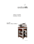
It is important that the Adhesive Rollers are placed into the TCH machine in the proper orientation. This is
to prevent the adhesive wrapping around the blue rubber rollers.
The orientation of the machine and web direction is taken when standing at the front of the opening cover..
Web Flow Direction Front to Back
The top adhesive roll must be loaded so that
the end with the red dot is loaded to the rear of
the machine and the bottom adhesive roll must
be loaded such that the end with the red dot is
loaded to the front of the machine
Web Flow Direction Back to Front
The top adhesive roll must be loaded so that
the end with the red dot is loaded to the front of
the machine and the bottom adhesive roll must
be loaded such that the end with the red dot is
loaded to the rear of the machine.
NOTE: IT IS GOOD PRACTICE TO TAPE DOWN THE CUT EDGE
Pi56377r05
ER3848r101
09.06.2011
10
6.3
HANDLING & CLEANING RUBBER ROLLERS
Always disconnect the machine form power supply before performing any cleaning operation.
6.3.1
NANOCLEEN ROLLERS
Rollers should only be touched wearing clean white cotton gloves (Mi51577) and should only be
cleaned with special Nanowipe cloth.
On a daily basis
Wipe the roller/s using the Nanowipe cloth dampened using clean water and wrung out until just
damp.
NEVER use Tekwipes, Isopropyl alcohol or other solvent cleaners on the Nanocleen rollers.
If the surface of the roller/s deteriorates or contamination is evident contact Technical Services for
assistance.
6.3.2
FILM, PANEL, ULTRACLEEN TYPE ROLLERS
On a daily basis
The rubber roller/s should be vigorously wiped using Tekwipes, Teknek Part No. Mi6700.
On a weekly basis
If the surface of the roller/s deteriorates or contamination is evident vigorously wipe down using
Scotchbrite Pad, Teknek Part number Pi5068 and Isopropyl alcohol together.
NOTE: Always allow Isopropyl alcohol to evaporate from the Film, Panel, F3 rollers before allowing
the Adhesive roll to come into contact with the rubber roller/s.
DO NOT USE ACETONE, SCREEN WASH OR ANY SOLVENT BASED CLEANER ON ANY
TEKNEK RUBBER ROLLER AS THIS WILL DAMAGE THE COMPONENT AND INVALIDATE
WARRANTY.
ENSURE THAT NO CLEANING LIQUID FLUIDS IMPREGNATE THE ADHESIVE ROLLER
SURFACES.
Pi56377r05
ER3848r101
09.06.2011
11
6.4
CLEANING ANTI-STATIC BAR
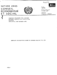
On a daily basis the anti-static bar should be cleaned to remove any contamination from the needle points,
using a soft brush (TEKNEK Part No. TK 5598). Failure to adhere to this instruction can diminish the
performance of the anti-static bar.
.
Pi56377r05
ER3848r101
09.06.2011
12
6.5
PREVENTATIVE MAINTENANCE SCHEDULE
TIMING
Each Shift or more
often if conditions
dictate
ACTION
REFER TO MANUAL
Purge
Adhesive Rollers
Section 6.1
Daily
Clean
Anti-Static Bar
Section 6.4
Weekly
Clean
Rubber Rollers
Section 6.3
Pi56377r05
ER3848r101
09.06.2011
13
6.6
LIST OF RECOMMENDED SPARES FOR PREVENTATIVE MAINTENANCE
6.6.1
PREVENTATIVE MAINTENANCE PARTS
MI6700
TEKWIPES TUB OF 65
1
(for use with Panel / Film / Ultracleen & F3 Rollers only
DO NOT USE ON NANOCLEEN ROLLERS
TK5598
MI5068
ANTI-STATIC BAR CLEANING BRUSH
1
SCOTCHBRITE PADS (ROLLER REJUVENATION)
5
(for use with Panel / Film / Ultracleen & F3 Rollers only
DO NOT USE ON NANOCLEEN ROLLERS
MI2393
6.6.2
STATIC BAR CHECKER
1
SPARES FOR 2 YEARS OPERATION
SP6563
GAS SPRING, AUTOSEP
2
BE0496
BEARING, ROLLER
2
SP1657
SPRING, FAIL-SAFE (W)
2
SP7244
SPRING, BEARING BLOCK
2
SP56369
SPRING, A/R SHAFT
1
HA56376
STATIC DRAIN BRUSH
2
PN56355
PISTON, 20 BORE – 25 STROKE
2
MA56375
A/R LIFT CAM
2
Pi56377r05
ER3848r101
09.06.2011
14
6.6.3
LENGTH ORIENTED PARTS
M/C
Width
Panel
R/Roller
Film
R/Roller
Ultracleen
R/Roller
Nanocleen
R/Roller
Antistatic
Bar
Adhesive
Roll Shaft
Adhesive
Roll
300
RR51246
RR51258
RU44367
RN53765
AB4925
PL56407
ARBS0300
400
RR51247
RR51259
RU44366
RN53766
AB19502
PL56408
ARBS0400
500
RR51248
RR51260
RU44365
RN53767
AB6620
PL56410
ARBS0500
600
RR51249
RR51261
RU44364
RN53768
AB3927
PL56411
ARBS0600
750
RR51250
RR51262
RU44363
RN53769
AB0637
PL56412
ARBS0750
910
RR51251
RR51263
RU44362
RN53770
AB0580
PL56413
ARBS0910
1000
RR51252
RR51264
RU44361
RN53771
AB0580
PL56414
ARBS1000
1100
RR51253
RR51265
RU44360
RN53772
AB0580
PL56415
ARBS1100
1200
RR51254
RR51266
RU44359
RN53773
AB0647
PL56416
ARBS1200
1300
RR51255
RR51267
RU44358
RN53774
AB0647
PL56417
ARBS1300
1400
RR51256
RR51268
RU44357
RN53775
AB3478
PL56418
ARBS1400
1500
RR51257
RR51269
RU44356
RN53776
AB3487
PL56419
ARBS1500
Pi56377r05
ER3848r101
09.06.2011
15
7
FAULT FINDING
POSSIBLE CAUSE
CORRECTIVE ACTION
i)
Check running pressure at regulator and
adjust.
Head coming down too quickly
or too slowly.
ii) Head going up too quickly or too
slowly.
Check running pressure at regulator and
adjust
iii) Head not staying horizontal during
lifting or lowering.
Uneven flow to pistons, adjust to correct.
iv) Adhesive paper wraps around
rubber roller.
Adhesive roll incorrectly installed.
Remove, check orientation and replace.
v) Contamination not being picked
up.
i) Check rubber roller is contacting workpiece, adjust if necessary.
ii) Check cleanliness of rubber roller.
Clean with Tekwipes.
iii) Ensure adhesive roll is purging
rubber roller. Remove outer layer
of adhesive roll.
vi) Head 'banging down' onto substrate
Adjust height setting of head as per
installation.
vii) Anti-static bars not operating.
Check and replace transformer.
Pi56377r05
ER3848r101
09.06.2011
16
8
CLEANING HEAD SPECIFICATION
MODELS OUTLINE DIMENSIONS: (IN OPERATING MODE)
Machine Type
WIDTH
(mm)
DEPTH
(mm)
HEIGHT
(mm)
TCH - 300
TCH - 400
TCH - 500
TCH - 600
TCH - 750
TCH - 910
TCH - 1000
TCH - 1100
TCH - 1200
TCH - 1300
TCH - 1400
TCH - 1500
492.5
572.5
692.5
794.5
934.5
1082.5
1172.5
1272.5
1358.5
1472.5
1572.5
1672.5
285
285
285
285
285
285
285
285
285
285
285
285
257
257
257
257
257
257
257
257
257
257
257
257
Est. WEIGHT
(kgs)
CONSTRUCTION & FINISH
Stainless Steel / Aluminium
FINISH
Polished Stainless Steel / Anodised Aluminium
CAPACITY/SPEED RANGE
Up to 100 MPM
POWER SUPPLY REQUIREMENTS
200/240v 110/115v
50/60 Hz
(POWERS ANTI-STATIC BAR AND SOLENOID
VALVE)
AIR
5-7 BAR – OIL FREE, 6mm INLET PIPE, AIR
CONSUMPTION IS NEGLIGABLE, ONLY
REQUIRED FOR ACTUATING THE MACHINE
ON / OFF.
Pi56377r05
ER3848r101
09.06.2011
17
9
DETAILED DRAWINGS
Drawing Number
Description
Pi56379
TD56380
TD56356
TD56406
PL56353
PL56373
PL56372
PL56371
PL56370
PL56351
PN56378
Technical Info
General Arrangement
Top Cover Assy
A/R Shaft Assembly
Lift Rod Assy
Endplate Assy – RH
Endplate Assy – LH
Endplate Assy - RH
End Assembly - LH
R/R Holder Assy
Pneumatic Schematic
Pi56377r05
ER3848r101
09.06.2011
18
10
APPENDIX
Pi56377r05
ER3848r101
09.06.2011
19