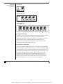
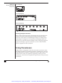
1
Artisan Technology Group is your source for quality
new and certified-used/pre-owned equipment
• FAST SHIPPING AND
DELIVERY
• TENS OF THOUSANDS OF
IN-STOCK ITEMS
• EQUIPMENT DEMOS
• HUNDREDS OF
MANUFACTURERS
SUPPORTED
• LEASING/MONTHLY
RENTALS
• ITAR CERTIFIED
SECURE ASSET SOLUTIONS
SERVICE CENTER REPAIRS
Experienced engineers and technicians on staff
at our full-service, in-house repair center
WE BUY USED EQUIPMENT
Sell your excess, underutilized, and idle used equipment
We also offer credit for buy-backs and trade-ins
www.artisantg.com/WeBuyEquipment
InstraView REMOTE INSPECTION
LOOKING FOR MORE INFORMATION?
Visit us on the web at www.artisantg.com for more
information on price quotations, drivers, technical
specifications, manuals, and documentation
SM
Remotely inspect equipment before purchasing with
our interactive website at www.instraview.com
Contact us: (888) 88-SOURCE | [email protected] | www.artisantg.com
Bridge Amp
Owner’s Guide
Artisan Technology Group - Quality Instrumentation ... Guaranteed | (888) 88-SOURCE | www.artisantg.com
This document was, as far as possible, accurate at the time of release. However,
changes may have been made to the software and hardware it describes since
then. ADInstruments Pty Ltd reserves the right to alter specifications as
required. Late-breaking information may be supplied separately.
Trademarks of ADInstruments
PowerLab®, LabTutor® and MacLab® are registered trademarks of ADInstruments
Pty Ltd. The names of specific recording units, such as PowerLab 8/30, are
trademarks of ADInstruments Pty Ltd. LabChart, Chart and Scope (application
programs) are trademarks of ADInstruments Pty Ltd.
Other Trademarks
Apple, Mac and Macintosh are registered trademarks of Apple Computer, Inc.
Windows, Windows XP and Windows Vista are either registered trademarks or
trademarks of Microsoft Corporation.
All other trademarks are the property of their respective owners.
Product: ML221 Bridge Amp; ML224 Quad Bridge Amp;
ML228 Octal Bridge Amp
Document Number: U-ML221-OG-002B
Part Number: 4708
Copyright © February 2008 ADInstruments Pty Ltd.
Unit 13, 22 Lexington Drive, Bella Vista, NSW 2153, Australia
All rights reserved. No part of this document may be reproduced by any means
without the prior written permission of ADInstruments Pty Ltd.
Web:
Technical Support:
Documentation:
www.adinstruments.com
[email protected]
[email protected]
ADInstruments Pty Ltd. ISO 9001:2000 Certified Quality Management System
Reg. No. 1053
ii
Bridge Amp Owner’s Guide
Artisan Technology Group - Quality Instrumentation ... Guaranteed | (888) 88-SOURCE | www.artisantg.com
Contents
Safety Notes
5
1 Overview
How to Use This Guide. . . .
Checking the Front-end. .
Front-end Fundamentals .
The Front-end . . . . . . . . .
The Front Panel . . . . . .
The Back Panel. . . . . . .
Using Transducers . . . . . .
Compatibility . . . . . . .
Suitable Transducers . . .
Unsuitable Transducers .
How Transducers Work .
Checking the Transducer .
13
.
.
.
.
.
.
.
.
.
.
.
.
.
.
.
.
.
.
.
.
.
.
.
.
.
.
.
.
.
.
.
.
.
.
.
.
.
.
.
.
.
.
.
.
.
.
.
.
.
.
.
.
.
.
.
.
.
.
.
.
.
.
.
.
.
.
.
.
.
.
.
.
.
.
.
.
.
.
.
.
.
.
.
.
.
.
.
.
.
.
.
.
.
.
.
.
.
.
.
.
.
.
.
.
.
.
.
.
.
.
.
.
.
.
.
.
.
.
.
.
.
.
.
.
.
.
.
.
.
.
.
.
.
.
.
.
.
.
.
.
.
.
.
.
.
.
.
.
.
.
.
.
.
.
.
.
.
.
.
.
.
.
.
.
.
.
.
.
.
.
.
.
.
.
.
.
.
.
.
.
.
.
.
.
.
.
.
.
.
.
.
.
.
.
.
.
.
.
.
.
.
.
.
.
.
.
.
.
.
.
.
.
.
.
.
.
.
.
.
.
.
.
.
.
.
.
.
.
.
.
.
.
.
.
.
.
.
.
.
.
.
.
.
.
.
.
.
.
.
.
.
.
.
.
.
.
.
.
.
.
.
.
.
.
.
.
.
.
.
.
.
.
.
.
.
.
.
.
.
.
.
.
.
.
.
.
.
.
.
.
.
.
.
.
.
.
.
.
.
.
.
.
.
.
.
.
.
.
.
.
.
.
.
.
.
.
.
.
.
.
.
.
.
.
2 Setting Up
PowerLab Requirements . . . . .
Software Requirements . . . . . .
Connecting to the PowerLab. . .
Multiple Front-ends . . . . . .
Using ADInstruments Programs
The Bridge Amp Dialog . . .
14
14
14
15
15
17
18
19
19
20
20
21
23
.
.
.
.
.
.
.
.
.
.
.
.
.
.
.
.
.
.
.
.
.
.
.
.
.
.
.
.
.
.
.
.
.
.
.
.
.
.
.
.
.
.
.
.
.
.
.
.
.
.
.
.
.
.
.
.
.
.
.
.
.
.
.
.
.
.
.
.
.
.
.
.
.
.
.
.
.
.
.
.
.
.
.
.
.
.
.
.
.
.
.
.
.
.
.
.
.
.
.
.
.
.
.
.
.
.
.
.
.
.
.
.
.
.
.
.
.
.
.
.
.
.
.
.
.
.
.
.
.
.
.
.
.
.
.
.
.
.
.
.
.
.
.
.
.
.
.
.
.
.
3 Adapting Transducers
Introduction . . . . . . . . . . . .
Transducer Adaptations . . . . .
Setting the Excitation Voltage
Wiring Up the Transducer . .
.
.
.
.
.
.
.
.
.
.
.
.
.
.
.
.
.
.
.
.
.
.
.
.
.
.
.
.
.
.
.
.
.
.
24
24
24
25
26
27
35
.
.
.
.
.
.
.
.
.
.
.
.
.
.
.
.
.
.
.
.
.
.
.
.
.
.
.
.
.
.
.
.
.
.
.
.
.
.
.
.
.
.
.
.
.
.
.
.
.
.
.
.
.
.
.
.
.
.
.
.
.
.
.
.
A Technical Aspects
.
.
.
.
.
.
.
.
.
.
.
.
.
.
.
.
.
.
.
.
.
.
.
.
36
36
37
38
41
Bridge Amp Operation . . . . . . . . . . . . . . . . . . . . . . . . . . . . . . . . 42
Technical Description . . . . . . . . . . . . . . . . . . . . . . . . . . . . . . . . . 43
Contents
Artisan Technology Group - Quality Instrumentation ... Guaranteed | (888) 88-SOURCE | www.artisantg.com
iii
B Troubleshooting
45
Problems . . . . . . . . . . . . . . . . . . . . . . . . . . . . . . . . . . . . . . . . 46
C Specifications
49
Single, Quad and Octal Bridge Amps (ML221, ML224 & ML228) . . . . . . . . 49
Index
iv
51
Bridge Amp Owner’s Guide
Artisan Technology Group - Quality Instrumentation ... Guaranteed | (888) 88-SOURCE | www.artisantg.com
Safety Notes
Statement of Intended Use
All products manufactured by ADInstruments are intended for use in
teaching and research applications and environments only.
ADInstruments products are NOT intended to be used as medical
devices or in medical environments. That is, no product supplied by
ADInstruments is intended to be used to diagnose, treat or monitor a
subject. Furthermore no product is intended for the prevention, curing
or alleviation of disease, injury or handicap.
Where a product meets IEC 60601-1 it is under the principle that:
•
•
it is a more rigorous standard than other standards that could be
chosen, and
it provides a high safety level for subjects and operators.
The choice to meet IEC 60601-1 is in no way to be interpreted to mean
that a product:
•
•
•
is a medical device,
may be interpreted as a medical device, or
is safe to be used as a medical device.
Safety Notes
Artisan Technology Group - Quality Instrumentation ... Guaranteed | (888) 88-SOURCE | www.artisantg.com
5
Safety Symbols
Devices manufactured by ADInstruments that are designed for direct
connection to humans are tested to IEC 601-1:1998 (including
amendments 1 and 2) and 60601-1-2, and carry one or more of the
safety symbols below. These symbols appear next to those inputs and
output connectors that can be directly connected to human subjects.
!
BF symbol: Bodyprotected equipment
CF symbol: Cardiacprotected equipment
Warning symbol: ‘see
documentation’
The three symbols are:
•
•
•
BF (body protected) symbol. This means that the input connectors
are suitable for connection to humans provided there is no direct
electrical connection to the heart.
CF (cardiac protected) symbol. This means that the input
connectors are suitable for connection to human subjects even
when there is direct electrical connection to the heart.
Warning symbol. The exclamation mark inside a triangle means
that the supplied documentation must be consulted for operating,
cautionary or safety information before using the device.
Further information is available on request.
Bio Amp Safety Instructions
The Bio Amp inputs displaying any of the safety symbols are
electrically isolated from the mains supply in order to prevent current
flow that may otherwise result in injury to the subject. Several points
must be observed for safe operation of the Bio Amp:
6
Bridge Amp Owner’s Guide
Artisan Technology Group - Quality Instrumentation ... Guaranteed | (888) 88-SOURCE | www.artisantg.com
•
•
•
All Bio Amp front-ends (except for the ML138 Octal Bio Amp) and
PowerLab units with a built-in Bio Amp are supplied with a 3-lead
or 5-lead Bio Amp subject cable and lead wire system. The ML138
Octal Bio Amp is supplied with unshielded lead wires (1.8 m). Bio
Amps are only safe for human connection if used with the
supplied subject cable and lead wires.
All Bio Amp front-ends and PowerLab units with a built-in Bio
Amp are not defibrillator-protected. Using the Bio Amp to record
signals during defibrillator discharges may damage the input
stages of the amplifiers. This may result in a safety hazard.
Never use damaged Bio Amp cables or leads. Damaged cables and
leads must always be replaced before any connection to humans is
made.
Isolated Stimulator Safety
Instructions
The Isolated Stimulator outputs of a front-end signal conditioner or
PowerLab with a built-in isolated stimulator are electrically isolated.
However, they can produce pulses of up to 100 V at up to 20 mA.
Injury can still occur from careless use of these devices. Several points
must be observed for safe operation of the Isolated Stimulator:
•
•
•
•
•
•
•
•
The Isolated Stimulator output must only be used with the
supplied bar stimulus electrode.
The Isolated Stimulator output must not be used with individual
(physically separate) stimulating electrodes.
Stimulation must not be applied across the chest or head.
Do not hold one electrode in each hand.
Always use a suitable electrode cream or gel and proper skin
preparation to ensure a low-impedance electrode contact. Using
electrodes without electrode cream can result in burns to the skin
or discomfort for the subject.
Subjects with implantable or external cardiac pacemakers, a
cardiac condition, or a history of epileptic episodes must not be
subject to electrical stimulation.
Always commence stimulation at the lowest current setting and
slowly increase the current.
Stop stimulation if the subject experiences pain or discomfort.
Safety Notes
Artisan Technology Group - Quality Instrumentation ... Guaranteed | (888) 88-SOURCE | www.artisantg.com
7
•
•
Do not use faulty cables, or those that have exhibited intermittent
faults.
Do not attempt to measure or record the Isolated Stimulator
waveform while connected to a subject using a PowerLab input or
any other piece of equipment that does not carry the appropriate
safety symbol (see Safety Symbols above).
Always check the status indicator on the front panel. It will always
flash green each time the stimulator delivers a current pulse. A yellow
flash indicates an ‘out-of-compliance’ (OOC) condition that may be
due to the electrode contact drying up. Always ensure that there is
good electrode contact at all times. Electrodes that are left on a subject
for some time need to be checked for dry contacts. An electrode
impedance meter can be used for this task.
•
•
Always be alert for any adverse physiological effects in the subject.
At the first sign of a problem, stimulation must be stopped, either
from the software or by flicking down the safety switch on the
front panel of any built-in Isolated Stimulator or the ML180
Stimulus Isolator.
The ML180 Stimulus Isolator is supplied with a special
transformer plug pack. The plug pack complies with medical
safety requirements. Therefore, under no circumstances should
any other transformer be used with the Stimulus Isolator. For a
replacement transformer plug pack please contact your nearest
ADInstruments representative.
General Safety Instructions
To achieve the optimal degree of subject and operator safety,
consideration should be given to the following guidelines when
setting up a PowerLab system either as stand-alone equipment or
when using PowerLab equipment in conjunction with other
equipment. Failure to do so may compromise the inherent safety
measures designed into PowerLab equipment. The following
guidelines are based on principles outlined in the international safety
standard IEC60601-1-1: General requirements for safety - Collateral
standard: Safety requirements for medical systems. Reference to this
standard is required when setting up a system for human connection.
8
Bridge Amp Owner’s Guide
Artisan Technology Group - Quality Instrumentation ... Guaranteed | (888) 88-SOURCE | www.artisantg.com
PowerLab systems (and many other devices) require the connection of
a personal computer for operation. This personal computer should be
certified as complying with IEC60950 and should be located outside a
1.8 m radius from the subject (so that the subject cannot touch it while
connected to the system). Within this 1.8 m radius, only equipment
complying with IEC60601-1 should be present. Connecting a system
in this way obviates the provision of additional safety measures and
the measurement of leakage currents.
Accompanying documents for each piece of equipment in the system
should be thoroughly examined prior to connection of the system.
While it is not possible to cover all arrangements of equipment in a
system, some general guidelines for safe use of the equipment are
presented below:
•
•
•
•
•
•
•
•
Any electrical equipment which is located within the SUBJECT
AREA should be approved to IEC60601-1.
Only connect those parts of equipment that are marked as an
APPLIED PART to the subject. APPLIED PARTS may be
recognized by the BF or CF symbols which appear in the Safety
Symbols section of these Safety Notes.
Only CF-rated APPLIED PARTS must be used for direct cardiac
connection.
Never connect parts which are marked as an APPLIED PART to
those which are not marked as APPLIED PARTS.
Do not touch the subject to which the PowerLab (or its peripherals)
is connected at the same time as making contact with parts of the
PowerLab (or its peripherals) that are not intended for contact to
the subject.
Cleaning and sterilization of equipment should be performed in
accordance with manufacturer’s instructions. The isolation barrier
may be compromised if manufacturer’s cleaning instructions are
not followed.
The ambient environment (such as the temperature and relative
humidity) of the system should be kept within the manufacturer’s
specified range or the isolation barrier may be compromised.
The entry of liquids into equipment may also compromise the
isolation barrier. If spillage occurs, the manufacturer of the affected
equipment should be contacted before using the equipment.
Safety Notes
Artisan Technology Group - Quality Instrumentation ... Guaranteed | (888) 88-SOURCE | www.artisantg.com
9
•
•
Many electrical systems (particularly those in metal enclosures)
depend upon the presence of a protective earth for electrical safety.
This is generally provided from the power outlet through a power
cord, but may also be supplied as a dedicated safety earth
conductor. Power cords should never be modified so as to remove
the earth connection. The integrity of the protective earth
connection between each piece of equipment and the protective
earth should be verified regularly by qualified personnel.
Avoid using multiple portable socket-outlets (such as power
boards) where possible as they provide an inherently less safe
environment with respect to electrical hazards. Individual
connection of each piece of equipment to fixed mains socketoutlets is the preferred means of connection.
If multiple portable socket outlets are used, they are subject to the
following constraints:
•
•
•
They shall not be placed on the floor.
Additional multiple portable socket outlets or extension cords
shall not be connected to the system.
They shall only be used for supplying power to equipment which
is intended to form part of the system.
Cleaning and Sterilization
ADInstruments products may be wiped down with a lint free cloth
moistened with industrial methylated spirit. Refer to the
manufacturer’s guidelines or the Data Card supplied with transducers
and accessories for specific cleaning and sterilizing instructions.
Preventative Inspection and
Maintenance
PowerLab systems and ADInstruments front-ends are all
maintenance-free and do not require periodic calibration or
adjustment to ensure safe operation. Internal diagnostic software
performs system checks during power up and will report errors if a
significant problem is found. There is no need to open the instrument
for inspection or maintenance, and doing so within the warranty
period will void the warranty.
10
Bridge Amp Owner’s Guide
Artisan Technology Group - Quality Instrumentation ... Guaranteed | (888) 88-SOURCE | www.artisantg.com
Your PowerLab system can be periodically checked for basic safety by
using an appropriate safety testing device. Tests such as earth leakage,
earth bond, insulation resistance, subject leakage and auxiliary
currents and power cable integrity can all be performed on the
PowerLab system without having to remove the covers. Follow the
instructions for the testing device if performing such tests.
If the PowerLab system is found not to comply with such testing you
should contact your PowerLab representative to arrange for the
equipment to be checked and serviced. Do not attempt to service the
device yourself.
Environment
Electronic components are susceptible to corrosive substances and
atmospheres, and must be kept away from laboratory chemicals.
Storage Conditions
•
•
Temperature in the range 0–40 °C
Non-condensing humidity in the range 0–95%.
Operating Conditions
•
•
Temperature in the range 5–35 °C
Non-condensing humidity in the range 0–90%.
Disposal
•
Forward to recycling center or return to manufacturer.
Safety Notes
Artisan Technology Group - Quality Instrumentation ... Guaranteed | (888) 88-SOURCE | www.artisantg.com
11
12
Bridge Amp Owner’s Guide
Artisan Technology Group - Quality Instrumentation ... Guaranteed | (888) 88-SOURCE | www.artisantg.com
Overview
1
The Bridge Amp is a modular device, in a family called front-ends,
designed to extend the capabilities of the PowerLab® system. The
Bridge Amp is designed to allow the PowerLab to connect to most DC
bridge transducers, including commonly available force transducers,
temperature probes, light meters, displacement transducers, pressure
transducers, and similar devices. This chapter provides an overview
of the various Bridge Amps, describes their basic features, and looks
at which transducers can be used with them.
Chapter 1 Overview
Artisan Technology Group - Quality Instrumentation ... Guaranteed | (888) 88-SOURCE | www.artisantg.com
13
How to Use This Guide
This owner’s guide describes how to set up and begin using your
Bridge Amp. The chapters give an overview of front-ends in general
and the Bridge Amp in particular, and discuss how to connect the
hardware, perform a simple power-up test, and use the Bridge Amp
with some ADInstruments programs. The appendices provide
technical information about the front-ends, and take a look at some
potential problems and their solutions.
At the end of this guide, you’ll find an index. Technical terms that are
not defined in the glossary of terms included with the owner’s guide
for your PowerLab are defined as they appear.
Checking the Front-end
Before connecting the Bridge Amp to anything, check it carefully for
signs of physical damage.
1. Check that there are no obvious signs of damage to the outside of
the front-end casing.
2. Check that there is no obvious sign of internal damage, such as
rattling. Pick up the front-end, tilt it gently from side to side, and
listen for anything that appears to be loose.
If you have found a problem, contact your authorized ADInstruments
representative immediately, and describe the problem. Arrangements
can be made to replace or repair the front-end.
Front-end Fundamentals
The PowerLab system consists of a recording unit and application
programs that run on the computer to which the unit is connected. It
is an integrated system of hardware and software designed to record,
display, and analyze experimental data. Your Bridge Amp is one of a
family of front-ends meant for use with your PowerLab system.
Front-ends are ancillary devices connected to the PowerLab recording
unit to extend the system’s capabilities. They provide additional
signal conditioning and other features, and extend the types of
experiments that you can conduct and the data you can record. All
ADInstruments front-ends are designed to be operated under full
software control. No knobs, dials or switches are needed, although
some may be provided for reasons of convenience or safety.
14
Bridge Amp Owner’s Guide
Artisan Technology Group - Quality Instrumentation ... Guaranteed | (888) 88-SOURCE | www.artisantg.com
The PowerLab controls front-ends through an expansion connector
called the I2C (eye-squared-sea) bus. Each new front-end added to the
system connects to the back of the previous front-end, in a simple
daisy-chain structure. This makes it very easy to add front-ends to the
system or to transfer them between PowerLabs. In general, each
front-end requires one analog input of the PowerLab. (Note that the
Quad Bridge Amp acts as if it were four individual Bridge Amps and
the Octal Bridge Amp, as if it were eight.)
Front-ends are automatically recognized by the PowerLab system.
Any front-end feature, such as gain or filtering, is combined with the
appropriate features of the software and presented as a single set of
software controls. This seamless integration of front-ends greatly
increases the flexibility and ease of use of the PowerLab system.
The Front-end
The Bridge Amp is designed to allow the PowerLab to connect to most
DC bridge transducers, including commonly available force
transducers, temperature probes, light meters, displacement
transducers, pressure transducers, and similar devices. There are
several models of Bridge Amp. The Bridge Amp provides just one
connection for a bridge transducer, the Quad Bridge Amp provides
four connections for bridge transducers and the Octal Bridge Amp
provides eight connections for bridge transducers.
Grass transducers can connect to any ADInstruments Bridge Amp
using a Grass adapter cable available from ADInstruments. Use the
MLAC11 Grass Adapter Cable to connect a Grass transducer to the
ML221, ML224 or ML228 Bridge Amp.
The rest of this chapter contains general information about the
features, connections and indicators of the Bridge Amps. More
detailed information can be found in the technical appendices.
The Front Panel
The front panel of a Bridge Amp has a single socket for a transducer
connection, a status indicator light and an overload indicator light.
The front panel of a Quad or Octal Bridge Amp has four or eight
transducer connections, respectively, each of which has a status
indicator light and an overload indicator light.
Chapter 1 Overview
Artisan Technology Group - Quality Instrumentation ... Guaranteed | (888) 88-SOURCE | www.artisantg.com
15
Figure 1–1
The front panels of the
Bridge Amps
ML221 Bridge Amp
ML224 Quad Bridge Amp
ML228 Octal Bridge Amp
The Input Socket
Transducers are connected to a Bridge Amp using the eight-pin DIN
sockets on the front panel. The sockets provide terminals for
supplying a transducer with power and for receiving the transducer
output. Front-ends are supplied with DIN plug kits (one per
connection) to be fitted to those transducers that lack them. The
connection is discussed in more detail later.
The Status Indicator
The Status indicator of the Bridge Amp is located at the bottom right
of the front panel, and the Status indicators of the Quad Bridge Amp
and Octal Bridge Amp are located beneath each connector on the front
panel. When an ADInstruments program such as LabChart starts up,
the Status indicator light should glow green, indicating that the
program has found the front-end, checked and selected it, and is
ready to use it. If the light does not glow when the program is
running, this indicates either that the front-end is not connected
properly or that there is a software or hardware problem.
16
Bridge Amp Owner’s Guide
Artisan Technology Group - Quality Instrumentation ... Guaranteed | (888) 88-SOURCE | www.artisantg.com
The Overload Indicator
The Overload indicator is located on the left side of the front panel of
the Bridge Amp and to the right of the Status indicator on the Quad
and Octal Bridge Amps.
The Overload indicator is normally off. If the indicator lights when a
transducer is attached, it indicates an out-of-compliance condition
(meaning that the excitation voltage drops because too much current
is being drawn by the load). When the Bridge Amp detects a problem
with the transducer (for instance a wiring fault with a transducer
causing a short-circuit), the overload indicator will glow yellow or
amber and will remain on until the fault is rectified.
If the overload indicator remains on with a transducer attached, the
transducer should be removed immediately to minimize the risk of
damage to the transducer. Check the transducer wiring carefully
before re-attaching the transducer. If the fault persists, refer to the
Troubleshooting section of this Owner’s Guide.
For the overload indicator to function, power must be applied to the
Bridge Amp via a PowerLab. LabChart software does not need to be
loaded.
When a software application is running and a channel is being zeroed,
the Status indicators for the other channels should temporarily be off.
The Back Panel
The back panel of the Bridge Amp provides all the sockets required to
connect the Bridge Amp to the PowerLab and to other front-ends.
I2C Input and Output Sockets
Two nine-pin sockets are used to communicate with the PowerLab
(they are marked ‘I2C Bus’: a ‘bus’ is simply information-transmission
circuitry such as cables and connectors). These sockets allow multiple
front-ends to be used independently with one PowerLab. Power and
control signals to the front-ends come from the PowerLab. Many
front-ends can be connected to the system, in series, output to input,
providing there is the same number of channel inputs available on the
PowerLab (this is discussed in more detail in the next chapter).
Chapter 1 Overview
Artisan Technology Group - Quality Instrumentation ... Guaranteed | (888) 88-SOURCE | www.artisantg.com
17
Figure 1–2
The back panels of the
Bridge Amps
ML221 Bridge Amp
ML224 Quad Bridge Amp
ML228 Octal Bridge Amp
Analog Output Sockets
BNC sockets on the back panel of the Bridge Amp provide the signal
outputs to connect to the analog input sockets on the front of the
PowerLab. The sockets are labelled Signal Output on a Bridge Amp
and Output 1 to Output 4 or 8 on Quad or Octal Bridge Amps. You
don’t have to match the channel numbers when connecting outputs to
inputs, but it helps to prevent confusion if you do. A BNC-to-BNC
cable is supplied for each connection.
Using Transducers
Bridge Amps are designed to allow the PowerLab to connect to most
DC bridge transducers, including commonly available force, pressure,
and displacement transducers, temperature probes, light meters, and
similar devices. They are capable of supporting various powered
transducers, and certain low-impedance unpowered (or self-powered)
transducers.
18
Bridge Amp Owner’s Guide
Artisan Technology Group - Quality Instrumentation ... Guaranteed | (888) 88-SOURCE | www.artisantg.com
However, because transducers vary in sensitivity and suitability, you
should read the following sections before connecting a transducer to a
Bridge Amp.
Compatibility
Transducers which operate with the ML110, ML112, ML118, ML119
will operate with the ML22x Bridge Amps. The ML110 and ML112
amplifiers had provision for increasing offsetting resolution via an
optional resistor installed in the transducer connector. Transducers
which have this offsetting resistor fitted will operate with the ML22x
Bridge Amps without modification.
Suitable Transducers
The Bridge Amps are designed to connect to transducers that require
DC excitation voltages, such as DC strain-gauge or semiconductor
transducers.
If you are uncertain about the suitability of your transducer, please
provide ADInstruments with an accurate circuit of the transducer and
a sample, and we will see about testing the device for compatibility.
Half-bridge transducers will need to be wired up with compensating
resistors before they can be used with any of the Bridge Amps
(see Chapter 3).
DC Strain-gauge. These are full-bridge or half-bridge transducers
requiring a DC excitation voltage, and output voltages of less than
200 mV full scale. They include strain-gauge force transducers,
temperature transducers and pressure transducers.
Semiconductor. These are powered transducers typically used for
light, displacement, and temperature measurements, giving output
voltages less than 200 mV full scale.
Generally, a Bridge Amp can be used with transducers that:
• require DC excitation voltages, not AC
• have transducer output voltages less than 5 V full scale
• have transducer impedances less than 10 kΩ.
Chapter 1 Overview
Artisan Technology Group - Quality Instrumentation ... Guaranteed | (888) 88-SOURCE | www.artisantg.com
19
Unsuitable Transducers
Some transducers are not supported and should not be used with the
Bridge Amp. These include LVDT, capacitive bridge, piezoelectric and
high-voltage transducers.
LVDT (linear variable differential transformer). This type of
transducer requires AC excitation voltages. The Bridge Amp is for use
with transducers requiring DC excitation. Connecting an LVDT
transducer to the Bridge Amp may damage the transducer.
Capacitive Bridge. These transducers require AC excitation. The
Bridge Amp is for use with transducers requiring DC excitation.
Piezoelectric. These transducers are not recommended owing to the
relatively low input impedance of the single Bridge Amp
(piezoelectric transducers typically need amplifiers with input
impedances of tens of megohms), and their half-bridge configuration.
High-voltage. Transducers generating more than ±5 V full scale will
exceed the input range of the Bridge Amp. A high-voltage powered
transducer may require some signal attenuation.
How Transducers Work
The Bridge Amp can connect to most bridge-type transducers, hence
its name. The term ‘bridge’ refers to the circuit configuration that is
normally called a Wheatstone bridge. These transducers come in two
forms: full-bridge and half-bridge. Some explanation is given here of
bridge-type transducers, although there are of course other types that
work differently, such as the semiconductor transducer.
The full-bridge circuit is fairly versatile, in that the circuit elements,
shown as the rectangular boxes in Figure 1–3, can be resistive,
capacitive, or thermal circuit elements, allowing the bridge to measure
force, pressure, temperature, and so forth. This circuit produces an
electrical output in proportion to an appropriate stimulus applied to
one or more of the four elements. Because of the balancing effect of the
four elements, high precision is possible. Full-bridge transducers
should work without problems.
A half-bridge transducer only uses half of the full-bridge circuit. It
consists of two elements of equal value with an excitation voltage
applied across them. The output of the transducer is taken at the
junction of the two elements.
20
Bridge Amp Owner’s Guide
Artisan Technology Group - Quality Instrumentation ... Guaranteed | (888) 88-SOURCE | www.artisantg.com
Figure 1–3
Left, a full-bridge
transducer; right, a halfbridge transducer
positive excitation
–
positive excitation
+
+
Bridge elements —
resistors, thermistors,
capacitors, or a mixture
negative excitation
negative excitation
The circuit forms a simple voltage divider. If one of the elements
changes value owing to an external stimulus, the output voltage will
also change. In practice, this configuration is not often used.
Half-bridge transducers will require adapting with compensating
resistors before use with a Bridge Amp.
Checking the Transducer
Before attempting to connect any transducer to a Bridge Amp, you
will need to determine the three things listed below. (This information
is normally supplied with the transducer; if not, you should consult
the manufacturer or supplier of the transducer.)
1. If the transducer requires an excitation voltage, and if so, what the
maximum excitation voltage, or recommended range, is for the
transducer.
2. The configuration of the transducer wiring connections.
3. If the transducer is a bridge-type transducer, and whether it has a
full-bridge or half-bridge configuration.
Transducers supplied by ADInstruments are supplied pre-adjusted,
and need no adjustment.
Do not attempt to connect the signal leads from the transducer to the
Bridge Amp if the wiring configuration is not known. Connecting an
incorrectly wired transducer to an excitation source is likely to
damage both the transducer and Bridge Amp.
Chapter 1 Overview
Artisan Technology Group - Quality Instrumentation ... Guaranteed | (888) 88-SOURCE | www.artisantg.com
21
Unpowered transducers, or those with their own power supply, do
not have to be supplied with any excitation voltage from the Bridge
Amp: they supply their own signal to it directly. The wiring
connections should still be carefully checked before connection, along
with transducer impedance and output voltage. Such transducers do
not need the excitation range to be adjusted from the default setting.
If they have low output voltages, though, then it is possible that their
offset ranges require adjusting.
Using Grass Transducers with DIN Bridge Amps
Most Grass transducers should have an impedance of about 350 Ω or
so. A few Grass and Grass-compatible transducers have a much lower
impedance, of about 250 Ω.
22
Bridge Amp Owner’s Guide
Artisan Technology Group - Quality Instrumentation ... Guaranteed | (888) 88-SOURCE | www.artisantg.com
Setting Up
2
This chapter describes connecting your Bridge Amp to your PowerLab
and performing a quick test to make sure that it is working properly.
The best way to configure your system for one or more front-ends is
discussed, along with how to use the Bridge Amp with
ADInstruments application software.
Chapter 2 Setting Up
Artisan Technology Group - Quality Instrumentation ... Guaranteed | (888) 88-SOURCE | www.artisantg.com
23
PowerLab Requirements
The ML221, ML224 and ML228 Bridge Amps will only operate with
newer models of PowerLabs, such as the /SP, /20, /26 and /30 series.
Software Requirements
The ML221, ML224 and ML228 Bridge Amps require the following
versions of ADInstruments software applications:
•
•
•
•
LabChart version 6, or later, for Windows or Macintosh
Chart version 5.4.2, or later, for Windows or Macintosh
Scope for Windows version 3.7.8, or later
Scope for Macintosh version 4.0.3, or later.
Note: the Bridge Amps will not operate with earlier versions of these
applications. Free updates are available from the ADInstruments
website for users with earlier versions of Chart 5 and Scope. If you
have queries regarding hardware and software requirements of the
Bridge Amps, please contact your local ADInstruments representative.
Connecting to the PowerLab
Connect your Bridge Amp, to the PowerLab, as follows:
•
•
•
Ensure that the PowerLab is turned off. Failure to do this may
damage the PowerLab, the Bridge Amp, or both.
Connect the I2C output of the PowerLab to the I2C input of the
front-end using the I2C cable provided.
Connect a BNC cable from each signal output, on the rear of the
Bridge Amp, to an input on the front panel of the PowerLab.
Note that the Quad Bridge Amp acts just as if it were four individual
Bridge Amps; the Octal Bridge Amp, eight. The I2C connections are
internal, though, so there is only one I2C cable needed to connect the
Quad or Octal Bridge Amps to the recording unit.
Check that the plugs for the I2C bus are screwed in firmly and the
BNC cables have firm connections. Loose connectors can cause erratic
front-end behavior, or may cause the front-end to fail to work at all.
BNC cables can lie under the front-end to keep them out of the way.
24
Bridge Amp Owner’s Guide
Artisan Technology Group - Quality Instrumentation ... Guaranteed | (888) 88-SOURCE | www.artisantg.com
Figure 2–1
Connecting a front-end to
the PowerLab: a PowerLab
has only one I2C output,
and each front-end has one
I2C output and one I2C input
Front-end I2C input
I2C connector cable
Front-end signal output
BNC connector cable
PowerLab I2C output
Multiple Front-ends
Multiple front-ends can be connected up to a PowerLab. The number
that can be connected depends on the number of inputs on the
PowerLab. The initial front-end should be connected as shown in
Figure 2–1. The remainder are daisy-chained via I2C cables,
connecting the I2C output of the last connected front-end to the I2C
input of the next front-end to be added, as shown in Figure 2–2. The
BNC cable for each front-end is connected to one of the inputs of the
PowerLab (except where otherwise specified).
Figure 2–2
Connecting multiple
front-ends to the PowerLab
(two single front-ends
shown for simplicity)
Front-end I2C inputs
PowerLab I2C output
Front-end I2C output
Chapter 2 Setting Up
Artisan Technology Group - Quality Instrumentation ... Guaranteed | (888) 88-SOURCE | www.artisantg.com
25
Using ADInstruments Programs
Front-ends are used with PowerLabs and ADInstruments software
applications such as LabChart and Scope (see Software Requirements,
p. 24). The Bridge Amp’s amplification and filtering is combined with
that of the PowerLab and the program and presented as a single set of
software controls, in this case replacing the Input Amplifier dialog
with the Bridge Amp dialog. The LabChart Help Center and Scope
User’s Guide detail the Input Amplifier dialog, and explain relevant
terms and concepts.
The Front-end Driver
A driver is a piece of software the computer uses to drive a peripheral
device. In order for a front-end to be recognized by ADInstruments
applications, the appropriate front-end driver must be present. The
Bridge front-end driver is used with the Bridge Amp. Front-end
drivers are installed when ADInstruments applications are installed
on the computer.
LabChart and Scope for Macintosh keep separate drivers in the
Essential Files folder in the LabChart or Scope folder. LabChart for
Windows has them built in, and Scope for Windows has them in the
Essential Files folder in the Scope folder. To replace the drivers, you
generally need to reinstall the ADInstruments software.
The Bridge Amp Self-test
Once the Bridge Amp is properly connected to the PowerLab, and
when the proper software is installed on the computer, a quick check
can be performed on the Bridge Amp. To perform the self-test:
1. Turn on the PowerLab and check that it is working properly, as
described in the owner’s guide that was supplied with it.
2. Once the PowerLab is ready, open the ADInstruments program
such as LabChart or Scope.
3. While it starts up, keep a close eye on the Status and Overload
indicators on the Bridge Amp. During initialization, the Status
indicators glow green, flash briefly, and then remain lit.
If the indicator glows green, the Bridge Amp is working properly, and
you can quit the application. If a light does not go on when the
program is started, this indicates either that the front-end is not
connected properly or that there is a software or hardware problem.
26
Bridge Amp Owner’s Guide
Artisan Technology Group - Quality Instrumentation ... Guaranteed | (888) 88-SOURCE | www.artisantg.com
If the overload light glows yellow (or amber) on any Bridge Amp, this
indicates some fault such as a short circuit, a badly wired bridge
transducer, or an excitation overload. In the first instance, check your
cable connections and transducers, and repeat the self-test. If this does
not solve the problem, contact your ADInstruments representative.
When a Bridge Amp is properly connected to the PowerLab, the
Input Amplifier… menu command are replaced by Bridge Amp… for the
input channel to which it is connected. If the application fails to find a
front-end connected, the normal text remains. If you were expecting a
connected front-end and see the normal text instead, you should quit
the application, turn the PowerLab off and check the connections.
Then restart the PowerLab and the application.
The documentation for LabChart and Scope does not cover front-endspecific features. These features are described in detail here for
LabChart. For the most part, dialogs for LabChart and Scope should
be much the same.
The Bridge Amp Dialog
The Bridge Amp dialog allows software control of the various
amplifiers and filters in the Bridge Amp and PowerLab for an input.
The signal present at a PowerLab input is displayed so that you can
see the effects of changes straight away. Once the settings in the dialog
are changed, click OK to apply them.
To set up many inputs quickly, click the arrows at the top of the
dialog, or use the right or left arrow keys on the keyboard, to move to
the equivalent dialogs for adjacent inputs. This skips channels that
have their inputs turned off. The input number is shown at the top of
the dialog, and the channel title (if any) is shown in the vertical
Amplitude axis of the dialog.
Signal Display
The input signal is displayed so you can see the effect of changing the
settings — no data are in fact recorded when setting things up. Slowly
changing waveforms will be represented quite accurately, whereas
quickly changing signals will be displayed as a solid dark area
showing only the envelope (shape) of the signal formed by the
minimum and maximum recorded values. The average signal value is
shown at the top left of the display area.
Chapter 2 Setting Up
Artisan Technology Group - Quality Instrumentation ... Guaranteed | (888) 88-SOURCE | www.artisantg.com
27
Figure 2–3
The Bridge Amp dialog for
Windows (before zeroing)
Input selection
Average signal
value
Pause/Scroll
buttons
Range pop-up
Set the offset for
the Bridge Amp
Mains filter
Displays the
Units Conversion dialog
Figure 2–4
The Bridge Amp dialog for
Macintosh (after zeroing)
Input selection
Displays a voltmeter on screen for use
when setting the offset externally
Average signal
value
Range pop-up
Set the offset for
the Bridge Amp
Mains filter
Pause/Scroll
button
Displays a voltmeter on screen for use
when setting the offset externally
Displays the
Units Conversion dialog
28
Bridge Amp Owner’s Guide
Artisan Technology Group - Quality Instrumentation ... Guaranteed | (888) 88-SOURCE | www.artisantg.com
You can stop the signal scrolling by clicking the Pause button at the
bottom left (Macintosh) or top right (Windows) of the data display
area. On the Macintosh this changes to the Scroll button. Click the
Scroll button to start scrolling again.
Shift and stretch the vertical Amplitude axis, by clicking and dragging
it in various ways, to make the best use of the available display area. It
functions the same as the Amplitude axis of the Chart window,
controls are identical and any change is applied to the Chart Window.
On a Macintosh, Show Range Axis in the Scale pop-up menu displays
the range axis at the right of the display area, and the Compression
buttons adjust the horizontal axis of the data display area.
Setting the Range
The Range pop-up menu lets you select the input range or sensitivity
of the channel (combined range of the PowerLab and Bridge Amp).
Changing the range in the Bridge Amp dialog is equivalent to
changing it in the Chart window. The default setting is 5 V and the
ranges go down to 200 μV in 14 steps.
Filtering
The filtering options provided are appropriate to the type of
transducers used with the Bridge Amp, and the signals usually
measured, which tend to be of lower frequency. Low-pass filters allow
you to remove high-frequency components, such as noise, from an
input signal. The Mains filter allows you to remove interference at the
mains frequency (typically 50 or 60 Hz).
Low-Pass Filtering. The Low Pass pop-up menu provides a choice of
filters to remove high-frequency components from the signal. They
are: 1, 2, 10, 20, 100, and 200 Hz, and 1 kHz. (The highest frequency
you can actually record is limited by the transducer you use: such
information should be in the documentation supplied with it.)
Mains Filter (/20, /25 and /30 series PowerLabs only). The Mains filter
checkbox allows you to filter out interference at the mains frequency
(typically 50 or 60 Hz). Note that in general it is better to prevent
interference at its source than to filter it. The mains filter is an adaptive
filter which tracks the input signal over approximately 1 second. It
analyzes the signal and creates a template of any interference due to
the mains frequency (see Appendix C). Subtraction of the template
from the incoming signal cancels most of the interference.
Chapter 2 Setting Up
Artisan Technology Group - Quality Instrumentation ... Guaranteed | (888) 88-SOURCE | www.artisantg.com
29
In comparison with a notch filter, this method produces little
waveform distortion and attenuates harmonics of the mains frequency
as well as the fundamental; it effectively removes non-sinusoidal
interference, such as that commonly caused by fluorescent lights.
The filter should not be used when:
•
•
•
•
the interference changes rapidly. The filter takes about 1 second to
adapt to the present level. If interference is present, and then is
suddenly removed, interference in the filtered signal will
temporarily be increased.
your signal contains repetitive components at frequencies close to
the mains frequencies.
your signal is already free from interference. If the signal-to-noise
ratio is greater than about 64 the mains filter introduces more noise
than it removes.
you are recording at close to maximum sampling rates. The mains
filter uses some of the PowerLab's processing power and therefore
reduces the maximum rate at which you can sample.
The template is not fully generated until about 1 second after
sampling starts and so the mains filter is not fully effective in the first
second of each data block.
Anti-alias
Click the Anti-alias checkbox to turn anti-aliasing on and off. Aliasing
is distortion caused by frequencies of the incoming biological
waveform that are more than half the sampling frequency. If you
monitor physiological signals with a low-pass filter setting of 100 Hz,
but you are only sampling at 100 Hz, aliasing may cause the recorded
waveform to be quite different from the actual signal. An analogy can
be seen in older Western films: spoked wagon wheels appear to stop
or even go backwards when their rate of rotation matches the film
frame speed – obviously not an accurate record of the wheels’ motion.
To prevent aliasing, the sampling rate must be at least twice the rate of
the highest expected frequency of the incoming waveform. For
example, if monitoring an ECG with maximum frequency
components of 100 Hz, the sampling rate needs to be at least 200 Hz to
provide an accurate signal. The sampling rate could be increased
further if fast spikes or peaks (such as in the QRS complex of an ECG)
must be accurately recorded. A high sampling rate, however, will use
more computer memory and may limit recording time.
30
Bridge Amp Owner’s Guide
Artisan Technology Group - Quality Instrumentation ... Guaranteed | (888) 88-SOURCE | www.artisantg.com
Inverting the Signal
The Invert checkbox allows you to invert the signal on the screen. It
provides a simple way to change the polarity of the recorded signal
without having to swap the connections to the recording electrodes.
For example, you might be recording from a force transducer where
an increase in force downwards gives a negative signal, but you want
to have a downwards force shown as a positive signal on the screen.
Checking the Invert checkbox will change the display to do this.
Offset Adjustment
Transducers almost always produce some amount of signal, usually
small, when in the equilibrium or rest state. Offset from a zero reading
need to be removed, in a process called zeroing. Commonly, the user
also wants to remove a constant term, for example baseline blood
pressure or initial tension in a muscle, from a measurement of interest.
This enables more accurate measurement of the changes in the signal
under stimuli. The offset controls in the Bridge Amp dialog can be
used to zero the reading manually or automatically.
Figure 2–5
The Offset controls,
Windows (left) and
Macintosh (right)
Manual Zeroing. The up and down arrows near the Zero button allow
manual adjustment of the signal offset. Click the up arrow to shift the
signal positively and the down arrow to shift it negatively. The shift
by clicking the arrow buttons depends on the range setting. At high
ranges the increments are larger to adjust the offset efficiently.
Automatic Zeroing. To perform automatic zeroing, click Zero: the
program works out a corrective DC voltage that cancels, as closely as
possible, the output voltage from the transducer. Auto-zeroing may
take about 20 seconds to work out the best zeroing value at all ranges.
A dialog with a progress bar appears: click the Cancel button or type
Command-period to stop the zeroing process. If there is still offset
after auto-zeroing, then Option-click the up and down arrow buttons
to adjust the zeroing slightly, by the smallest increment at any range.
Chapter 2 Setting Up
Artisan Technology Group - Quality Instrumentation ... Guaranteed | (888) 88-SOURCE | www.artisantg.com
31
Note. Variations in the transducer signal during the auto-zeroing
operation will cause the software to fail to zero the offset properly, if it
zeroes at all. Make sure that the transducer is kept still and that no
varying signal is applied during the operation.
The offset display, a small numeric indicator above the Zero button,
shows the corrective voltage used to adjust for transducer offset. The
offset is given in the units of the channel. When the Bridge Amp is
first powered up, the software sets the offset circuit to its default
position (no offset adjustment of the transducer) and the offset display
value is zero. When either Zero or the manual offset controls are
clicked, this value will change to indicate the positive or negative
corrective adjustment.
On a Macintosh, click the small 0 button to restore the offset circuit to
its initial, non-zeroed position (and the offset display value to zero).
This can be used to determine the offset generated by a transducer.
Display Offset
Click Display Offset… to display the Input Value dialog (Figure 2–6).
A voltmeter displays the voltage currently being measured for an
input (the input channel is indicated at the top of the dialog). If a
transducer or some other external equipment has offset adjustment
capabilities, you can use this to zero it.
Figure 2–6
The Input Value dialog,
Windows (left) and
Macintosh (right)
Because the dialog allows for such fine adjustment, a vertical arrow
appears indicating the zero point if the offset is substantial. This
dialog is not a control, simply an indicator that acts like a voltmeter.
32
Bridge Amp Owner’s Guide
Artisan Technology Group - Quality Instrumentation ... Guaranteed | (888) 88-SOURCE | www.artisantg.com
Units
Click Units… to display the Units Conversion dialog, with which you
specify the units for the channel and, using waveform measurements,
calibrate the channel. The waveform in the data display area of the
Bridge Amp dialog is transferred to the data display area of the Units
Conversion dialog. (Use the Pause button to capture a specific signal.)
The units conversion only applies to subsequently recorded signals, so
it is more limited than choosing Units Conversion… from a Channel
Function pop-up menu, as it does not allow conversion of individual
blocks or pages of data.
Chapter 2 Setting Up
Artisan Technology Group - Quality Instrumentation ... Guaranteed | (888) 88-SOURCE | www.artisantg.com
33
34
Bridge Amp Owner’s Guide
Artisan Technology Group - Quality Instrumentation ... Guaranteed | (888) 88-SOURCE | www.artisantg.com
Adapting
Transducers
3
This chapter describes the modifications that may be required to
connect third-party transducers to the Bridge Amp. Transducers
supplied by ADInstruments should connect directly without
modification, so if using those you need not read this chapter.
If you are using powered third-party transducers with your Bridge
Amp you may need to adapt them using the information provided
here.
NOTE: Please ensure that any modifications made to transducers are
carried out by experienced technical staff, as incorrect wiring may
damage the transducer or Bridge Amp. If you are unsure, please
contact your nearest ADInstruments representative for further
assistance.
Chapter 3 Adapting Transducers
Artisan Technology Group - Quality Instrumentation ... Guaranteed | (888) 88-SOURCE | www.artisantg.com
35
Introduction
Conventional amplifiers usually have controls on the front to adjust
for the connected transducer: this means making adjustments each
time you change transducers or amplifiers.
Front-ends controlled by ADInstruments software are designed to be
easily transferred between recording units, and to be quick to
disconnect and reconnect, so it makes more sense to adapt the
transducer. The change needs only be done once for any third-party
transducer, which can then be used with any Bridge Amp with the
same connector. Once set up, multiple transducers will work with the
same Bridge Amp without needing further adjustment, and one can
simply change connected transducers as required.
Some soldering of components is required to adapt third-party
transducers for use with your Bridge Amp. If you have little
experience with electronics and no technician to assist you, your
ADInstruments representative should be able to help.
Types of Bridge Amp and Adaptation
The ML118 Quad and ML119 Octal Bridge Amps have a fixed
excitation voltage of 8 V (±4 V with respect to ground). You cannot
adjust the offset voltage range of the zeroing circuit for these frontends. Adapting powered transducers for them is relatively simple.
Transducer Adaptations
This section covers adapting transducers for use with the
ADInstruments Bridge Amps.
To connect transducers that require some form of power supply from
the Bridge Amp, first read this section carefully. The requirements of
the transducer should be determined before attempting to connect it.
To adapt a transducer for use with the Bridge Amp, you need to:
•
•
36
set the excitation voltage for the transducer
wire the transducer to use the eight-pin DIN plug.
Bridge Amp Owner’s Guide
Artisan Technology Group - Quality Instrumentation ... Guaranteed | (888) 88-SOURCE | www.artisantg.com
You will need the following equipment:
•
•
•
a soldering iron and resin-cored solder (ONLY resin-cored solder)
an eight-pin DIN-style male plug with 45-degree pin spacing
(supplied with your Bridge Amp)
common E12 resistors: 0.25 or 0.125 Watt, 2% or 1% metal film.
Setting the Excitation Voltage
The first step in preparing a powered transducer for use with the
Bridge Amps is to set the required excitation voltage. Two of the pins
in the Bridge Amp’s DIN socket can provide up to 20 volts DC as
excitation voltage to power the transducer. The voltage is varied by a
resistor fitted between the two corresponding pins of the transducer’s
DIN plug. When no resistor is present, the Bridge Amp’s internal
circuitry cuts off all voltage to prevent mishaps. Once a resistor is
fitted, the correct excitation voltage is provided automatically when
the transducer is plugged into the Bridge Amp.
Table 3–1
Transducer excitation
voltage and resistance
Excitation voltage
(DC volts)
Excitation
resistance
(Ω)
Excitation voltage
(DC volts)
Excitation
resistance
(Ω)
20
Short circuit
5
470 k
18
12 k
4
560 k
15
47 k
3.5
680 k
12
100 k
3
820 k
10
150 k
2.5
1M
8
220 k
2
1.2 M
6
330 k
To program the excitation voltage for a particular transducer, choose a
value of resistance from Table 3–1 to match the required excitation
voltage for your transducer. In most cases, you should be able to get
close to the required excitation voltage by selecting one of those
values. We recommend that the excitation resistor be 0.25 or 0.125
Watt, 2% or 1% metal film. Larger resistors may not fit in the confined
space of the transducer’s DIN plug.
In general, the output voltage from the transducer is directly
proportional to the excitation voltage placed across it. The greater the
excitation voltage, the more sensitive the transducer becomes.
Chapter 3 Adapting Transducers
Artisan Technology Group - Quality Instrumentation ... Guaranteed | (888) 88-SOURCE | www.artisantg.com
37
However, transducers have a limit to the level of excitation voltage
that can be applied before they are damaged. Some resistive elements
may start to heat at high excitation voltages, causing their resistance to
change. This degrades the accuracy of the transducer. High voltages
may also damage capacitive bridge transducer elements. To avoid
problems, the excitation voltage should be set according to the
manufacturer’s recommendation for that transducer.
To set the excitation voltage for a transducer, you will need to solder
the chosen resistor between pins 5 and 8 of the eight-pin DIN plug, as
shown in Figure 3–1. Mount the resistor as shown for maximum
clearance within the plug.
Figure 3–1
Installing the programming
resistor (the pins are
labeled on the plug)
Pin 5
Excitation voltage
programming
resistor
Pin 8
Wiring Up the Transducer
The second step in preparing a powered transducer for use with the
Bridge Amp is to wire the transducer to the DIN plug.
There are several things to note when wiring up transducers:
1. Make sure that the transducer wiring passes through the casing
before soldering the wires to the plug.
2. The transducer wires should be cut, stripped and tinned prior to
soldering, to ensure a good connection.
3. The pin numbers shown in the diagrams are the numbers marked
on most standard DIN plugs. If the plug has no numbers or
different ones, go by the layout shown here.
Wiring Up a Full-Bridge Transducer
This procedure should be used to wire full-bridge transducers only,
not half-bridge transducers. The transducer lead wires should be
soldered to the pins of the DIN plug as shown in Figure 3–2.
38
Bridge Amp Owner’s Guide
Artisan Technology Group - Quality Instrumentation ... Guaranteed | (888) 88-SOURCE | www.artisantg.com
Any unused wires from the transducer should be cut and insulated to
prevent shorting of signals or damage to the equipment.
7
Signal positive (+)
5
3
Ground or centre tap (shield)
8
Signal negative (–)
6
2
Figure 3–2
The wiring connections for
a full-bridge transducer,
looking at the DIN plug
from the cable side
Excitation positive (+)
1
4
Excitation negative (–)
Excitation
voltage
programming
resistor
The main insulation sheath of the transducer wiring should be
clamped with the strain-relief device within the plug, so that it just
clears the excitation voltage resistor. The transducer will normally
have some sort of cable shield, which should be connected to pin 7 of
the DIN plug. If the casing of the DIN plug is metal, it is
recommended and good practice to ensure that the casing will also be
connected to the shield.
Figure 3–3
The correct length of
wiring to the DIN plug
Wire from
transducer
Transducer ground
(earth) wire
The Finished Transducer
After connecting the excitation voltage programming resistor and
wiring up the transducer to the DIN plug, the transducer should now
be fully configured for your application. The excitation voltage will be
set automatically when you plug the transducer into the Bridge Amp.
Chapter 3 Adapting Transducers
Artisan Technology Group - Quality Instrumentation ... Guaranteed | (888) 88-SOURCE | www.artisantg.com
39
40
Bridge Amp Owner’s Guide
Artisan Technology Group - Quality Instrumentation ... Guaranteed | (888) 88-SOURCE | www.artisantg.com
A P P E N D I X
A
A
Technical
Aspects
This appendix describes some of the important technical aspects of the
Bridge Amp to give some insight into how it works. You do not need
to know the material here to use the Bridge Amp. It is likely to be of
special interest to the technically minded, indicating what the Bridge
Amp can and cannot do, and its suitability for particular applications.
(You should not use it as a service manual: user modification of the
equipment voids your rights under warranty.)
Appendix A Technical Aspects
Artisan Technology Group - Quality Instrumentation ... Guaranteed | (888) 88-SOURCE | www.artisantg.com
41
Bridge Amp Operation
The Bridge Amp and other ADInstruments front-ends have been
designed to integrate fully with the PowerLab system. The Bridge
Amp is essentially an extension of the PowerLab’s input amplifiers, so
the amplification (and hence the ranges) offered in LabChart and
Scope are the combination of both pieces of hardware. The
Bridge Amp provides:
•
•
•
•
Figure A–1
Block diagram of the
ML221 Bridge Amp. The
ML224 and 228 Bridge
Amps are similar but with
four or eight inputs,
respectively
the additional amplification necessary to deal with the low signal
outputs of most transducers
additional programmable filtering, to remove unwanted signal
frequencies
a stable DC excitation voltage supply for powering the transducer
digitally-controlled transducer zeroing circuitry.
Gain
control
Transducer
plug
Transducer
signal inputs
Pre-amp
5th-order
8 kHz
Butterworth
low-pass
filter
Prog.
Amp
Signal
Output
Overload
indicator
Excitation
voltage
Excitation voltage
setting resistor
+
–
Bridge
excitation
driver
16-bit
DAC
Vref
I2C
control
interface
+
power
supply
I2C
Outpu t
I2C
Input
Online indicator
42
Bridge Amp Owner’s Guide
Artisan Technology Group - Quality Instrumentation ... Guaranteed | (888) 88-SOURCE | www.artisantg.com
Technical Description
The PowerLab provides control and low-voltage power to front-ends
through a special expansion connector called the I2C (eye-squaredsea) bus. Front-ends are also connected to the analog inputs of the
recording unit via a BNC-to-BNC cable. The overall operation of the
Bridge Amps can be better understood by referring to Figure A–1.
The digital control interface used to control filter settings, gain,
coupling, and zeroing circuits uses an I2C interface system, which
provides a 4-wire serial communication bus to the recording unit and
other front-ends. All control of the Bridge Amp is through this bus.
Also present on the I2C connector is a set of power supply rails
derived from the recording unit. The Bridge Amp has its own
on-board regulators to ensure a stable power supply.
The input stage consists of a low-drift instrumentation amplifier with
programmable gain (fully software-controlled). The gain of this stage
is combined with the gain of the recording unit to give a total gain of
up to 50 000 (at this amplification, 200 μV is full scale). From the input
amplifier, the signal is passed to a fixed fifth-order, low-pass, filter.
The filter allows a range of cutoff frequencies to be selected under
software control.
The excitation voltage output circuit is a complementary output stage,
derived from a stable internal voltage reference, capable of giving up
to ±10 volts (20 volts DC) excitation. The excitation voltage for each
channel is completely independent from other channels. The
transducer excitation voltage can be adjusted by connecting a resistor
between two pins on the plug that plugs into the Bridge Amp’s input
socket. This resistor is usually placed inside the transducer’s DIN
plug so that the transducer will always get the correct excitation
voltage when it is connected.
To remove any offsets caused by an attached transducer or signal
baseline, a DC offset circuit with a 16-bit DAC (digital-to-analog
converter). This is internally connected to the input stage. Transducer
offsets are zeroed by applying a corrective DC voltage to the input
stage via the DAC, under software control.
The DAC is only capable of producing corrective voltages in discrete
steps.
Appendix A Technical Aspects
Artisan Technology Group - Quality Instrumentation ... Guaranteed | (888) 88-SOURCE | www.artisantg.com
43
44
Bridge Amp Owner’s Guide
Artisan Technology Group - Quality Instrumentation ... Guaranteed | (888) 88-SOURCE | www.artisantg.com
A P P E N D I X
B
B
Troubleshooting
This appendix describes most of the common problems that can occur
when using the Bridge Amp with your PowerLab recording unit. It
covers how these problems are caused, and what you can do to
alleviate them. If the solutions here do not work, earlier chapters, the
LabChart Help Center, and the guide to your PowerLab may contain
possible solutions. If none of the solutions here or elsewhere are of
help, then consult your ADInstruments representative.
Most of the problems that users encounter are connection problems,
and can usually be fixed by checking connections and starting up the
hardware and software again. Very rarely will there be an actual
problem with the Bridge Amp or the PowerLab itself.
Appendix B Troubleshooting
Artisan Technology Group - Quality Instrumentation ... Guaranteed | (888) 88-SOURCE | www.artisantg.com
45
Problems
The Status indicator fails to light when the software is started, or the
Bridge Amp… command does not appear where it should
The I2C cable or one or more BNC-to-BNC cables from the Bridge
Amp to the PowerLab are not connected, have been connected
incorrectly (to the wrong input, for instance), or are loose.
•
Turn everything off. Check to see that all cables are firmly inserted
and screwed in. Make sure the input is the same channel from
which you expect to use the Bridge Amp in the software. Ensure
no other equipment is attached to the particular channel of the
Powerlab from which you expect to see the Bridge Amp. Start up
again to see if this has fixed the problem.
You are using an early version of LabChart or Scope.
•
Upgrade to the latest version of the software. Contact your
ADInstruments representative for information.
The BNC or I2C cable is faulty.
•
Replace the cable and try again. Immediately label all cables
proved faulty so that you don’t use them again by accident.
The Bridge Amp is faulty.
•
This is the least likely event. If the Bridge Amp will not work
properly after the previous measures, then try using it on another
PowerLab. If the Bridge Amp’s Status indicator fails to light with a
second PowerLab, the Bridge Amp may be faulty. Contact your
ADInstruments representative to arrange for repairs.
One or more overload indicators glow amber
If a light glows amber (yellow), it indicates some fault such as a short
circuit, a badly wired bridge transducer, or an excitation overload.
46
•
Check to see that all transducer connections are firm.
•
Check for short circuits and badly wired bridge transducers, by
changing them around, connecting new ones, and so on.
•
Check transducer impedances. In particular, a low-impedance
Grass transducer (250 Ω or so) may suffer overload if the
excitation is too high.
Bridge Amp Owner’s Guide
Artisan Technology Group - Quality Instrumentation ... Guaranteed | (888) 88-SOURCE | www.artisantg.com
On starting up the software, an alert indicates that there is a problem
with the front-end or driver
The correct Bridge driver is not installed on your computer (it should
be in the Essential Files folder, inside the LabChart or Scope folder).
•
Reinstall the software.
You are using an early version of LabChart or Scope.
•
Upgrade to the latest version of the software. Contact your
ADInstruments representative for information.
The BNC or I2C cable is faulty.
•
Replace the cable and try again. Immediately label all cables
proved faulty so that you don’t use them again by accident.
The Bridge Amp is faulty.
•
This is the least likely event. If the Bridge Amp will not work
properly after the previous measures, then try using it on another
PowerLab. If the Bridge Amp’s Status indicator fails to light with a
second PowerLab, the Bridge Amp may be faulty. Contact your
ADInstruments representative to arrange for repairs.
The trace will not zero properly when using the automatic or manual
zeroing controls
Variations in the transducer signal during auto-zeroing may cause the
software to fail to zero the offset properly, if it zeroes at all.
•
Make sure that the transducer is kept still and that no varying
signal is applied during auto-zeroing.
The transducer is defective or subject to excessive load, causing the
offset range of the Bridge Amp’s zeroing circuitry to be exceeded.
•
Check the transducer with another Bridge Amp if possible and try
again. Contact the supplier or manufacturer of the transducer if
there still seems to be a problem.
You are using an unmodified half-bridge transducer.
•
Half-bridge transducers may require rewiring with compensating
resistors before they can be used with Bridge Amps.
Appendix B Troubleshooting
Artisan Technology Group - Quality Instrumentation ... Guaranteed | (888) 88-SOURCE | www.artisantg.com
47
The signal from the transducer is noisy at lower ranges
This is usually the amplified noise from the transducer and its
associated circuitry, not a fault as such.
•
Set the low-pass filter to remove the noise.
The signal from the transducer is weak even at lower ranges
The connection to the transducer may be connected incorrectly, or
may be loose or disconnected. Adaptations within the plug may be
faulty or badly wired up.
•
Check the connection and try again. If the transducer has been
adapted for use with the Bridge Amp, check the wiring and
soldering within the plug.
•
Ensure that the particular channel in LabChart has been correctly
recognized as a Bridge Amp (and not as Input Amplifier).
The transducer itself is faulty.
•
Check the transducer with another Bridge Amp if possible and try
again. Contact the supplier or manufacturer of the transducer if
there still seems to be a problem.
The signal from the transducer drifts excessively.
48
•
Both the Bridge Amp and transducer require time to reach thermal
equilibrium. Allow 5 minutes of warm-up time with the
transducer connected and then try to re-zero the transducer.
•
The transducer itself may be of low quality.
•
The excitation voltage may be too high and causing the transducer
to self-heat and drift. Try reducing the excitation voltage.
Bridge Amp Owner’s Guide
Artisan Technology Group - Quality Instrumentation ... Guaranteed | (888) 88-SOURCE | www.artisantg.com
A P P E N D I X
C
C
Specifications
Single, Quad and Octal Bridge Amps
(ML221, ML224 & ML228)
Input
Number of inputs:
1 (single), 4 (Quad) or 8 (Octal); 8-pin DIN
Input configuration:
Differential
Amplification range:
±200 μV to ±5 V full scale in 14 steps
(combined PowerLab and Bridge Amp)
±5V
±2V
±1V
± 500 mV
± 200 mV
± 100 mV
± 50 mV
± 20 mV
± 10 mV
± 5 mV
± 2 mV
± 1 mV
± 500 μV
± 200 μV
Amplification accuracy:
±0.5% (combined PowerLab and Bridge Amp)
Maximum input voltage:
±10 volts
Input impedance:
2 × 1 MΩ (single-ended) 2 MΩ (differential)
Low-pass filtering:
1 Hz to 1 kHz in seven steps (softwareselectable)
Appendix C Specifications
Artisan Technology Group - Quality Instrumentation ... Guaranteed | (888) 88-SOURCE | www.artisantg.com
49
Frequency response (–3 dB): 2 kHz maximum at all gains with the low-pass
filter off
CMRR (differential):
100 dB @ 50 Hz (typical)
Input noise:
<1 μVrms referred to input at highest gain
Excitation and Zeroing
Excitation voltage range:
0–20 volts DC (±10 V referred to ground),
adjusted by external resistor
Transducer drive current:
±45 mA maximum
Zeroing circuitry:
Software-controlled, either manual or automatic
Internal offsetting range:
±10 V (1 V–5 V range)
±1 V (100 mV–500 mV range)
±100 mV (200 μV–50 mV)
Internal offset resolution:
16-bit (internal DAC) ±32 000 steps about 0 V.
1, 2, 5 V - 310 μ V/step
100 mV, 200 mV, 500 mV - 31 μ V/step
200 μV to 50 mV - 3 μV/step
Control Port
I2C port:
Power and control bus for front-end units.
Supports a number of front-ends dependent on
the PowerLab. Interface communications rate of
~50 kbits/s.
Physical Configuration
Weight and Dimensions (h × w × d):
Single (ML221):
Quad (ML224):
Octal (ML228):
50 mm × 76 mm × 260 mm (1.97" × 3.0" × 10.2");
710 g
60 mm × 200 mm × 250 mm (2.36" × 7.9" × 9.8");
1.5 kg
60 mm × 300 mm × 300 mm (2.36" × 11.8" × 11.8");
3.4 kg
Power requirements:
0.8 W (ML221); 2.5 W (ML224); 5.0 W (ML228)
(without transducer attached)
Operating conditions:
5–35 °C, 0–90% humidity (non-condensing)
ADInstruments reserves the right to alter these specifications at any time.
50
Bridge Amp Owner’s Guide
Artisan Technology Group - Quality Instrumentation ... Guaranteed | (888) 88-SOURCE | www.artisantg.com
Index
A
F
adapting transducers 35–39
ADInstruments programs 26–33
aliasing 30
analog output 18
automatic zeroing 31
filtering 29
front panel 15–17
front-end driver 26, 47
front-ends, general 14–15
full-bridge transducers 20, 38–39
B
H
back panel 17–18
block diagram 42
Bridge Amp models 15
bridge amp software 27–33
half-bridge transducers 20
how transducers work 20–21
C
impedances, maximum 19
input socket 16
I2C bus 15, 17, 43
checking the front-end 14
checking transducers 21
cleaning 10
connections
multiple front-ends 25
single front-end 24
to the PowerLab 24–25
D
digital-to-analog converter 43
DIN socket 16
display offset 32
I
L
LabChart 26
M
maintenance 10
manual zeroing 31
O
offset adjustment 31–32
offset display 32
overload indicator 17
E
excitation overload 17
excitation voltage 36, 37–38
P
PowerLab system 14
Index
Artisan Technology Group - Quality Instrumentation ... Guaranteed | (888) 88-SOURCE | www.artisantg.com
51
S
Safety Notes 5–11
Scope 26
self-test 26
Status indicator 16
storage 10
suitable transducers 19
T
technical specifications 49–50
transducer
capacitive bridge 20
DC strain-gauge 19
high-voltage 20
LVDT 20
piezoelectric 20
semiconductor 19
transducers
adapting 35–39
checking 21
DIN 36–39
full-bridge 20, 38–39
Grass 22
half-bridge 20
how they work 20–21
suitable 19
unsuitable 20
U
unsuitable transducers 20
user modification 41
using ADInstruments programs 26–33
using this guide 14
V
voltmeter 32
Z
Zero button 32
zeroing 31–32
automatic 31
manual 31
52
Bridge Amp Owner’s Guide
Artisan Technology Group - Quality Instrumentation ... Guaranteed | (888) 88-SOURCE | www.artisantg.com
Artisan Technology Group is your source for quality
new and certified-used/pre-owned equipment
• FAST SHIPPING AND
DELIVERY
• TENS OF THOUSANDS OF
IN-STOCK ITEMS
• EQUIPMENT DEMOS
• HUNDREDS OF
MANUFACTURERS
SUPPORTED
• LEASING/MONTHLY
RENTALS
• ITAR CERTIFIED
SECURE ASSET SOLUTIONS
SERVICE CENTER REPAIRS
Experienced engineers and technicians on staff
at our full-service, in-house repair center
WE BUY USED EQUIPMENT
Sell your excess, underutilized, and idle used equipment
We also offer credit for buy-backs and trade-ins
www.artisantg.com/WeBuyEquipment
InstraView REMOTE INSPECTION
LOOKING FOR MORE INFORMATION?
Visit us on the web at www.artisantg.com for more
information on price quotations, drivers, technical
specifications, manuals, and documentation
SM
Remotely inspect equipment before purchasing with
our interactive website at www.instraview.com
Contact us: (888) 88-SOURCE | [email protected] | www.artisantg.com