1
1980 SRX440
FOREWORD
This Service Manual has been written to acquaint the mechanic with the
disassembly. reassembly. maintenance. and troubleshooting procedures required to provide optimum performance and longevity of the machine.
The information herein should be closely studied to avoid unnecessary repairs and to provide the owner with a sound. safe. dependable machine.
NOTE:------------
_
The Research and Engineering Departments of Yamaha are continually
striving to further perfect all models. Improvements and modifications are
therefore inevitable.
In light of this fact. all specifications within this manual are subject to
change without notice. Information regarding changes is forwarded to all
Authorized Yamaha Dealers as soon as available.
YAMAHA MOTOR CO" LTD.
SERVICE DEPARTMENT
Particularly important information is distinguished in this manual by the following notations:
NOTE:
CAUTION:
WARNING:
A NOTE provides key information to make procedures
easier or cleaner.
A CAUTION indicates special procedures that must be followed to avoid damage to the machine.
A WARNING indicates special procedures that must be followed to avoid injury to a machine operator or person inspecting or repairing the machine.
SECTION INDEX
GENERAL
ENGINE
COOLING SYSTEM
CARBURETION
POWER TRAIN
CHASSIS
.~
ELECTRICAL
APPENDIX
1980 SRX440
CHAPTER 1. GENERAL
1-1.
EXTERNALVIEW.
1-2
1-2.
MACHINE IDENTIFiCATION
1-3
1-3.
1-4.
A.
Frame serial number.
1-3
B.
Engine serial number
1-3
MAINTENANCE INTERVALS CHARTS
1-4
A.
Periodic maintenance
1-4
B.
Lubrication intervals
1-5
HIGH ALTITUDE TUNING
1-6
1980 SRX440
CHAPTER 1. GENERAL
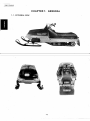
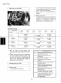
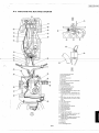
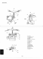
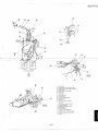
1-1. EXTERNAL VIEW
1-2
1980 SRX440
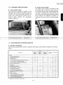
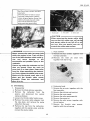
1-2. MACHINE IDENTIFICATION
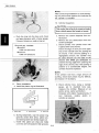
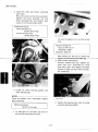
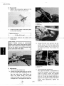
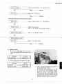
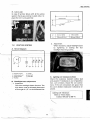
B. Engine serial number
The engine serial number is located on the
right-hand side of crankcase cover. The prefix indicates engine type and displacement.
The prefix is followed by a dash and the SElrial number. Normally both frame and engine
serial numbers are identical; however, on
occasion they may be two or three numbers
off.
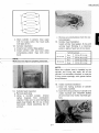
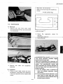
A. Frame serial number
The frame serial number is located on the
righthand side of frame (just below the front
of seat). The first three digits identify the
model. This is followed by a dash. The remaining digits identify the production
number of the unit.
Frame starting serial number
8K6-015101
Engine starting serial number
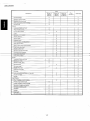
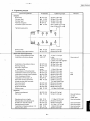
1-3. MAINTENANCE INTERVALS CHARTS
A. Periodic maintenance
(Use this just as guide only. Certain conditions may require more frequent inspection of components.)
Every
Check point
20 hrs. or
400km
40 hrs. or
aOOkm
(250mi)
(500 mil
..
80 hrs. or
1,600 km
(1.000mi)
When
necessary
Seasonally
ENGINE:
Tightness of bolts and nuts
0
0
Bends, cracks and wear
0
0
Abnormal noise
0
0
Loose connection and breaks of fuel and pulse pipes
0
0
Loose connection and breaks of oil pipes
0
0
Loose connection and breaks of oil delivery pipe
0
Manual rope starter system
0
0
0
Carburetor
•
•
•
•
Operation of starter jet
0
0
Mixing adjuster (pilot screw)
Idling speed adjustment
Throttle valve synchronization
Operation and adjustment of oil pump
0
0
0
0
0
0
0
0
0
Ignition timing
0
Engine compressions
0
0
Cylinder head/exhaust pipe decarbonize
Spark plug condition, gap and cleaning
0
0
0
Tightening of the cylinder head ••
"'. Retighten every 10 hours from the first use.
1-3
1980 SRX440
Every
Check point
..
20 hrs. or
40 hrs. or
400km
800 km
(250mi)
(500mi)
80 hrs. or
1,600 km
(1.000 mil
When
necessary
Seasonally
Coolant leakage
0
Operation of thermostat
0
0
Operation of water pump
0
0
Water pump belt tension. damage
0
0
Coolant level
0
0
Tightness of bolts and nuts
0
0
Wear on slide runners
0
0
DRIVE
Primary drive system
0
0
V-belt
0
0
0
Secondary drive system
0
0
Sheave distance
0
0
Sheave offset
0
0
Brake pad wear
0
0
Brake operation and adjustment
0
0
Guide wheel rubber
0
0
Wear of drive track wheel sprocket
0
0
Drive track adjustment
0
0
Breaks in drive track
0
0
Bends in front and rear axles
0
0
Checking of lock washers
0
0
Drive chain adjustment
-mwe cnam 6if ever
0
0
<:Y
0
BODY'
Tightness of bolts and nuts
0
0
Bends and cracks
0
0
Welded riveted. joints
0
Ski adjustment
Ski runner wear
0
0
0
0
0
0
Breaks in fuel tank
0
Cleaning of fuel tank
0
Fuel filter
0
Loose connection and breaks in fuel pipe
0
0
Breaks in oil tank
0
0
Oilfifter
ElECTRICAL:
0
.
Wear, breakage of wire covering
0
Breaks in high-tension cord_
0
Voltage regulator working voltage
0
0
0
Operation of engine stop switch
0
0
Operation of tether switch
0
0
Headlight
0
0
Taillight
0
0
Brake light
0
0
Oil caution light
0
0
1-4
;=
1980 SRX440
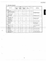
B. Lubrication intervals
Every
Check point
20 hrs. or
40Qkm
(250 mil
40 hrs. or
800 km
(500 mil
80 hrs. or
1,600 km
{1.000mil
When
necessary
Oil/Grease
Seasonally
Brand name
ENGINE:
Starter case
..
0
Speedometer drive housing
0
0
Water pump bearing and oil
seal
0
0
Oil pump control box
0
0
Pump drive cover
0
Oil in the oil tank
Aeroshell grease #7 A or
Esso Beacon 325 grease
0
YAMALUBE 2-cycle oil
0
DRIVE:
Primary sheave weight
and roller pins
0
0
Secondary shaft and
Sliding sheave
0
0
Front axle housing
0
0
light all-purpose grease
Shaft 1 and shaft 2
{Slide rail}
Drive chain oil
replacement
Molybdenum disulfide
snowmobile grease
0
0
0
0
Gear oil API "Gl-3"
SAE#750r#80
0
0
Light all-purpose grease
0
0
Motor oil
BODY:
Steering column lower
bearing
Steering column upper
Steerina links
0
Ski column
0
0
Light all-purpose grease
Ski wear plate
0
0
Ski retaining pin
0
0
Brake wire end stopper
and brake lever
0
0
1-5
Light all-purpose grease
Esso Beacon 325 grease
1980 SRX440
Tool name
Tool No.
Rotor holding tool
90890-01235
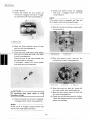
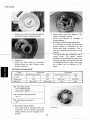
E. Primary sheave
Refer to "5-1-8. Primary sheave"
1. Rotor holding tool
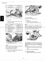
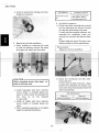
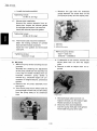
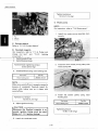
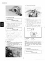
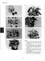
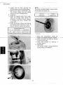
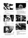
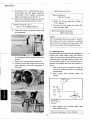
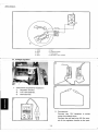
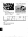
F. Oil pump
1. Remove the oil delivery pipes.
2. Remove the bolts and pump drive case.
3. Using the flywheel puller, remove the
flywheel assembly.
No.
4
5
Tool name
Tool No.
Drive handle
90890-01817
Flywheel puller screw
90890-01806
(q\8 X 80 mm)
Flywheel puller
attachment
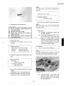
NOTE: - - - - - - - - - - The oil pump can be removed as an
um
drive
assembl to ether with the
cover. If it is hand to remove the pump drive
case. tap it with a soft-faced hammer.
90890-01804
CAUTION:---------,
The oil pump must not be disassembled,
because the oil pump is a precision
work.
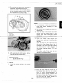
NOTE:-----------When removing the flywheel, the key must
be removed from the crankshaft.
Take care so that it is not lost.
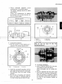
3. Remove the oil pump cap and pump
wire.
4. Remove the oil pump assembly.
3. Remove the Phillips-head screw, and
remove the coil plate.
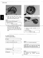
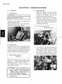
G. Engine disassembly.
1. Remove the thermostat case and joint.
2-4
L
1980 SRX440
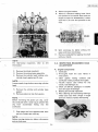
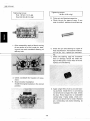
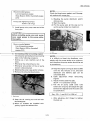
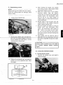
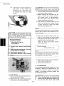
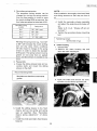
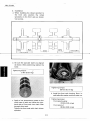
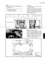
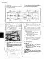
8. Remove engine bracket.
9. Remove crankcase holding bolts.. Each
bolt position is numbered, Start with the
largest number for disassembly. Loosen
each bolt 1/4 turns and proceed to the
next.
10. Split crankcase by lightly striking the
upper and lower crankcases.
11. Remove crankshaft by tapping the shaft
with your hands.
1\10 I E:
:~
For thermostat inspection. refer to
thermostat.
3-5
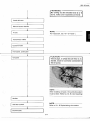
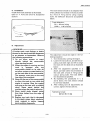
2-2. INSPECTION. REASSEMBLY AND
ADJUSTMENT
A. Engine components
1. Crankcase
a. Thoroughly wash the case halves in
mild solvent.
b. Clean gasket mating surfaces and
crankcase mating surfaces thoroughly.
c. Visually inspect case halves for any
cracks. road damage. etc.
d. Check oil delivery passages in transfer
ports for signs of blockage.
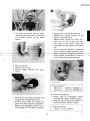
2. Bearing and oil seal inspection
a. After cleaning and lubricating bearings.
rotate outer race with a finger. If rough
spots are noticed. replace the bearing.
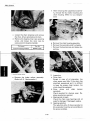
2. Remove the intake manifold.
3. Remove the exhaust pipe assembly.
4. Remove the cylinder head holding nuts.
cylinder head. gasket and a-ring.
NOTE: - - - - - - - - - - - - Loosen spark plugs before removing cylinder
head.
5. Remove the cylinder and cylinder base
gasket.
6. Remove piston pin clip from piston.
NOTE: - - - - - - - - - - - - Before removing the piston pin clip. cover
the crankcase with a clean rag to prevent the
clip from accidentally falling into the
crankcase.
7. Push piston pin from opposite side. then
pull out. Protect pin with rag.
NOTE:------------Before moving piston pin. deburr clip groove
and pin hole area.
2·5
1980 SRX440
b. Check oil seal lips for damage and wear.
Replace as required.
Crank bearing
Crankshaft oil seal
lip
Yamalube 2-cycle oil
Low temperature grease
(Esso Beacon 325 or
Aerosheli grease #7 AI
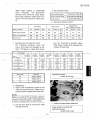
4. Crankshaft inspection
a. Check connection rod axial play at small
end (to determine. the amount of wear
of crank pin and bearing at big end).
If small end play exceeds tolerance. disassemble the crankshaft. check connecting rod. crank pin and big end bearmg.
Replace defective parts. Play after reassembly should be within specification.
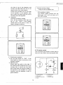
3. Bearing and oil seal installation
a. When installing or removing left crank
oil seal and bearing. remove the pump
drive gear and install new drive gear.
Rod axial play:
Maximum 2.0 mm (0.079 in)
b. Check the connecting rod side clearance at big end.
If axial play exceeds tolerance. disassemble the crankshaft and replace any
worn parts. Big end axial play should be
within specification.
CAUTlON:---------...,
When removing pump drive gear. replace it with new one.
b. Install bearing(s) with their manufacturer's marks or. numbers facing outward. (In other words. the stamped letexposedters must be on the
to-view-side.)
c. Install oil sealts) with their manufacturer's marks or numbers facing outward.
d. When installing bearing(s) or oil seatts).
apply the specified lubrication.
Rod side clearance
2-6
Minimum
Maximum
0.25 mm (0.010 inl
0.75 mm 10.030 in)
1980 SRX440
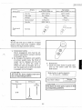
c. Check crankshaft assembly runout
(misalignment of crankshaft parts).
Dial gauge readings should be within
specification.
Correct any misalignment by tapping
the flywheel with a brass hammer and/or by using a wedge.
Deflection tolerance
Left side
Center
Center
(left)
(right)
0.03 mm
0.04mm
0.04mm
(0.0012 in) (0.0016 in) 10.0016 in)
Right side
0.05 mm
10.0020 in)
FWD
<>
80mm
~
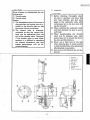
1. Knock pin
2. Sealing surface
3. Upper case
4. Aligning mark
CAUTION :--~-----'----,
The oil seal lip must fit into the
crankcase groove,
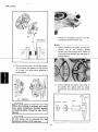
5. Crankshaft installation
a. Set the circlip on crank bearing as illustrated. (The primary sheave side.)
UPPER CASE
CD
I
o
FWD
<>
LOWER CASE
1. Circlip
2. Sealing surface
6. Crankcase installation
a. Apply YAMAHA BOND #4 to the mating surfaces of both case halves.
Apply thoroughly over all mating surfaces.
b. Set the crankcase half onto lower case
half. Install the crankcase holding bolts.
Each bolt position is numbered. Tighten
all crankcase holding bolts gradually in
the order of the numbers marked on
crankcase.
3. Knock-pin
b. Install the crankshaft assembly with oil
seal, align the bearing punch marks with
the crankcase lower and upper mating
surfaces.
c. Set the pins of bearing and labyrinth
seal in pin holes of crankcase upper by
moving the bearings and labyrinth seal.
2-7
1980 SRX440
.
Tightening torque:
40 Nm (4.0 m-kg)
Tightening torque:
First: 10 Nm (1.0 m-kg)
Final: 22 Nm (2.2 m-kg)
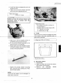
8. Piston pin and bearing inspection
a. Check the pin for signs of wear. If any
wear is evident. replace pin and bearing.
c. After reassembly, apply a liberal coating
of two-stroke oil to the crank pin, bearing and into each crankshaft bearing oil
delivery hole.
b. Check the pin and bearing for signs of
heat discoloration. If excessive (indentation on pin, etc.). replace pin and bearIn.
c. Check the bearing cage for excessive
wear or damage. Check the rollers for
signs of flat spots. If such wear is found,
replace pin and bearing.
d. Check crankshaft for freedom of movement.
7. Engine bracket installation
Install the engine brackets in the correct
position.
d. Apply a light film of oil to pin and bearing surfaces. Install them in connecting
rod small end to inspect for wear. Check
for play. There should be no noticeable
vertical play. If play exists, check connecting rod small end for wear. Replace
pin, connecting rod and/or bearing, as
required.
2-8
1980 SRX440
e. The piston pin should have no noticeable free play in the piston. If the piston
pin is loose, replace the pin and/or
piston.
e. Wash piston in solvent and wipe dry.
f. Measure the outside diameter of the
piston at the piston skirt.
Measurement should. be made at a
point 10 mm (0.5 in) above the bottom edge of the piston. Place the
micrometer at right angles to the piston
pin.
Piston maximum diameter subtracted
from minimum cylinder diameter gives
-----nrme-cylindel tbtblelallce 01 bOle to
next oversize and fit oversize piston.
9. Piston inspection
a. Remove piston rings.
b. Remove carbon deposits from piston
crown.
1. 10 mm (0.5 in)
Piston clearance:
Minimum " .. 0.065 mm (0.0026 in)
Maximum
0.070 mm (0.0028 in)
10. Piston ring inspection
a. Check rings for scoringlany severe
scratches are noticed, replace ring set.
b. Measure ring end gap in free position. If
beyond tolerance, replace ring set.
c. Carefully remove carbon deposits from
ring grooves with filed end of ring.
d. Remove score marks and lacquer deposits from sides of piston using 600 ~
800 grit wet sandpaper. Sand in a crisscross pattern. Do not sand excessively.
Ring end gap free:
Approx. 7.0 mm (0.28 in)
2-9
1980 SRX440
NOTE:-----------Take care during installation to avoid damaging the piston skirts against the crankcase as
the cylinder is installed.
12. Cylinder inspection
CAUTION: - - ' - - - - - - - - - . . . ,
This model has a hard chromed cylinder
bore. which cannot be honed or bored.
a. Remove the carbon deposits from exhaust port.
b. Remove the any obstructions from the
coolant passages.
c. Check cylinder. The cylinder inner wall
is plated with hard chrome.
Check the edge of each port and upper
area of the cylinder bore for peeling-off
of chrome. If the chrome peeling is a
negligeable amount. the cylinder may
be used. Smooth out the edge of the
chrome with #400 riLsandpaper to
prevent the ring edge from catching the
edge of the chrome. But if the peeling is
present to a considerable degree. the
cylinder should be replaced.
c. Push the ring into the bore and check
end gap clearance with a feeler gauge.
If beyond tolerance. replace ring set.
Ring end gap. installed:
Minimum:
0.35 mm (0.014 in)
Maximum:
0.55 mm (0.022 in)
NOTE: - - - - - - - - - - - If the cylinder wall has a large amount of
scuffing. check each piston ring for defects.
and replace it if necessary.
11. Piston installation
a. Install the piston ring as illustrated.
1. Piston head
2. Piston bottom
d. Check cylinder bore. Using a cylinder
gauge. set to standard bore size.
measure the cylinder. Measure at six
points; at top. center and bottom.
Compare with piston measurements. If
over tolerance. replace piston or
cylinder as required.
3. Piston ring
b. During reassembly. coat the piston ring
grooves. piston skirt areas. piston pin.
and bearing with two-stroke engine oil.
c. Install new piston pin clips and make
sure they are full-seated in their grooves.
2-10
1980 SRX440
2/~'
~/
----------
,--------
3
e. Clean cylinder in solvent, then
with hot soapy water. Dry. Coat
with light oil film.
13. Cylinder installation
a. Install a new cylinder base gasket.
b Install cylinder with one hand
compressing piston rings with
hand.
c. Remove any obstructions from the coolant passages.
15, Cylinder head installation
Install cylinder head gasket, D-ring and
cyiinder head. Working in a crisscross
pattern, tighten head nuts in two steps.
wash
walls
while
other
Tightening torque
First
20 Nm 12.0 m-kg)
Final
30 Nm 13.0 m-kq)
First
20 Nm 12.0 m-kq)
Final
25 Nm 12.5 m-kg)
10 mm nut
.
I~V
II:;
Makesuretnerin gs aI e properlvposttionad,
8 mm nut
.. ,""
NOTE: - - - - - - - - - - - When the cylinder head is installed on the
cylinder, the D-ring may easily fall off the
cylinder. 'It is advisable, therefore, to coat the
D-ring groove sparingly with grease before
this procedure.
16. Intake 'manifold installation
a. Clean the mating surfaces of cylinder
and intake manifold.
b. Coat the mating surfaces of cylinder and
intake manifold with YAMAHA BDN D
#4 and install new intake manifold gaskets.
14. Cylinder head inspection
a. Remove spark plug.
b. Using a rounded scraper, remove
carbon deposits from combustion
chamber. Take care to avoid damaging
spark plug threads. Do not use a sharp
instrument. Avoid scratching the aluminum.
2-11
1980 SRX440
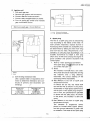
c. Install the intake manifold.
c. Measure the gap with the thickness
gauge between the raised boss on the
pump adjust pulley and the adjust plate.
Tightening torque:
15 Nm (1.5 m-kg)
17. Exhaust pipe installation
Remove the carbon deposits from exhaust pipe. Inspect the exhaust gasket
for damage and replace it as required.
Install the exhaust pipe with gasket.
Tightening torque:
23 Nm (2.3 m-kg)
18. Thermostat case and joint installation
Clean the mating surfaces of cylinder
head and thermostat case/joint.
Install the new gasket and thermostat
. t
case /'Jam.
1. Adjust plate
2. Adjust pulley
3. Minimum pump stroke
Minimum pump stroke:
0.20 ~ 0.25 mm
(0.0079 ~ 0.0098 in)
Tightening torque:
7 Nm (0.7 m-kg)
(}-+f clearance is not correct;-remove-the
adjust plate lock nut and the adjust
plate.
e. Remove or add an adjust shim as required.
B. Oil pump
1. Minimum pump stroke checking and adjustment.
Normally the checking the adjustment
of the pump stroke are not required. but
if any sign of trouble resulting from an
incorrect minimum pump stroke is
noticed (e.g.. excessive engine oil consumption or engine seizure). proceed as
follows:
a. Remove the oil pump assembly from
the engine.
b. Turn the oil pump worm Wheel until the
pump plunger moves fully out and away
from the pump body to its outermost
limit.
1. Adjust shim
f. Reinstall adjust plate and lock nut.
Tighten the lock nut. Re-measure gap.
Repeat procedure as required.
2. Oil pump drive case installation
Coat the pump drive gear with grease.
And install the pump drive case.
2-12
1980 SRX440
NOTE:--~-------
Recommended grease:
Low temperature grease
(Esso Beacon 325 or Aeroshell grease
#7A)
Check the bleed screw gasket. and if damaged. replace with a new one.
b. Bleeding the pump distributor and/or
delivery pipe.
1) Start the engine.
2) Pull the pump wire all the way out to
set the pump stroke to a maximum.
Pump case tightening torque:
10Nm(1.0m-kg)
3. Install pump wire, pump case and oil delivery pipe.
CAUTION:---------...,
Before installing pump wire and pump
case, apply grease to the pump pulley
thoroughly.
Recommended grease:
Low temperature grease
(Esso Beacon 325 or Aeroshell
grease #7A)
1. Pull
2. 1'00iipvvile
o
NOTE:
It is difficult to bleed the distributor completely with the pump stroke at a minimum,
and therefore the pump stroke should be set
to a maximum.
3) Keep the engine running at about 2,000
r/min for two minutes or so, and both
distributor and delivery pipe can be
completely bled.
5. Cable adjustment (After remounting
engine)
a. Adjust throttle cable free play.
(See 4-1-A. Carburetor tuning)
b. Pull the oil pump cable outer tube
toward the oil pump and adjust the gap
between the adjuster and the outer tube
to specification.
Play: 23
± 1 mm
(0.91
± 0.04 in)
1. Bleed screw
c. After adjusting, don't forget to tighten
the lock nut.
2) Keep the oil running out until air bubbles disappear.
3) When air bubbles are expelled completely, tighten the bleed screw.
2-13
1980 SRX440
Tightening torque:
10 Nm (1.0 m-kg)
E, Water pump
NOTE: - - - - - - - - - - - - For inspection, refer to "3-4 Water pump".
1. Install the water pump assembly temporarily.
1. Play
2. Adjuster
3. Lock nut
C. Primary sheave
Refer to "5-1 - B. Primary sheave".
D. Flywheel magento
(For inspection. refer to '7 -1-G. Pulser and
charge coil test" and "7-2-C. Lighting
circuit test'")
1. Install woodruff key.
------'Tln-sfilTI-f1ywheeTbase:··
2. Install the drive water pump pulley with
water pump belt.
Flywheel base tightening torque:
.
6 Nm (0.6 m-kg)
3. Install flywheel using rotor holding tool.
Tool name
Tool No.
Rotor holding tool
..90890-01235
NOTE: - - _ - - -
_
Make sure woodruff key is properly seated in
keyway of crankshaft. Carefully install flywheel while taking care so it aligns with
woodruff key.
3. Install the starter pulley using rotor
holding tool.
Flywheel nut torque:
73 Nm (7.3 m-kg)
Tool name
. 4. Adjust ignition timing.
Tool No .
90890-01235
Rotor holding tool
CAUTION: - -.....- - - - - - - .
Whenever the flywheel magneto is removed, ignition timing must be reset.
(Refer to 7-1-C. Ignition timing)
Tightening torque:
15 Nm (1.5 m-kg)
.
. .5. Install the crankcase cover.
2-14
..
_---_._-1980 SRX440
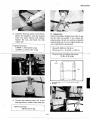
4.
By moving the water pump housing up
and down, adjust the belt tension.
Adjust the bolt so that the belt deflects
4 mm (0.16 in) when a force of 4 kg (9
Ib) is applied to the center of belt.
NOTE: - - - - - - - - - - - 1. It is necessary to wind the spring to a
small size before installing it in the
starter case.
2. Be careful not to install the spring in a
wrong way.
3. Hook the loop on the outer end of the
spring onto the spring hook in the
starter case. Then thoroughly grease
the s rin .
F: 4 kg (9 lbl
a: Center of belt
S: 4 mm (0.16 in)
2.
5. After adjusting the belt tension, tighten
the water pump housing bolts.
Windihe starter rope- -around the
sheave drum, and put it into the star- .
ter case.
Hook the knot on the rope end onto
the cut in the sheave drum (as illustrated), and wind the rope around
the sheave drum in the direction of
the arrow, leaving about 370 mm
(14.6 in).
The other end of the rope is connected to the starter handle.
Tightening torque:
9.5 Nm (0.95 m-kg)
F. Starter
1. Install the starter spring in the starter
case.
2-15
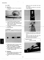
3. Bring the rope end out of the cut in
the sheave drum, and turn the sheave
drum 4 tu;hs counterclockwise to
give the starter spring preload. Pull
the starter handle and release it, making sure that the starter handle returns to the housing rope eye.
1980 SRX440
1. Drive plate spring
2. Drive pawl
3. Return spring
4. Place
the drive pawl, return spring,
.l
drive plate spring, drive plate and
tighten the thrust washer and nut.
NOTE:----~------
Grease the pivot of the drive pawl.
Tightening torque:
10Nm(1.0m-kg)
em y, c ec
the starter for smooth operation:
Pull out the starter rope about 80 ~
130 mm (3 ~ 5 in). and make sure that
the starter pawl moves out of the drive
plate.
6. Install the starter assembly on the.
crankcase.
Tightening torque:
7 Nm (0.7 m-kg)
G. Engine remounting
Install the engine as follows:
Engine
Engine mounting bolts and nuts
NOTE: - - - - - - - - - - - Refer to "5-1-A Sheave adjustment".
CAUTION: - - - - - - - - - . . . ,
Take care not to pinch the wire and
pipes between the engine and frame.
Magneto lead wire
Carburetor
NOTE:--------~--
For adjusting, see "4-1 Carburetor".
For
routing,
see
CABLE
ROUTING
DIAGRAM.
2-16 - - - - - - - - - - - - - - - -
1980 SRX440
WARNING: - - - - - - - - - - - ,
By turning out the throttle lever 2 or 3
turns, make sure it operates correctly.
Intake silencer
Manual starter handle
NOTE: - - - - - - - - - - , - - - For inspection, see "5-1-C V-bett".',
V-belt
Tachometer cable
Coolant hoses
Fuel pipes, pulse pipe
CAUTION:----------,
The oi I pipe, in which the oi I filter is installed, must be correctly connected to
the oil pump.
Oil pipes
NOTE: - - - - - - - - - - - After installing oil pipe. the autolube system
must be bled. (Refer to 2-2-8-4 Air bleeding).
Muffler
NOTE: - - - - - - - - - - - Refer to 3-1-D Replenishing the Coolant.
Add the coolant
Snowmobile
2-17
r
,.f
L·_ _--'-
~
__
1980 SRX440
CHAPTER 3. COOLING SYSTEM
3-1.
COOLANT
Coolant level
B. Coolant type
C. Draining the coolant
D. Replenishing the coolant
COOLING SYSTEM CHECK
A. Cooling system check
B. Radiator cap check
RADIATOR
A. Removal
B. Inspection
C. Installation
HEAT EXCHANGER
A.
Removal
B, Inspection
C. Installation
WATER PUMP
A. Disassembly
B. Inspection
C. ReasseM.bly
3-2
3-2
3-2
3-2
3-3
3-3
3-3
3-4
3-4
3-4
3-4
3-4
3-4
3-4
3-4
3-4
3-5
3-5
3-5
3-5
A.
3-2.
3-3.
3-4.
3-5.
A.
B.
C.
Removal
Inspection
Installation
,
"
:
3-6
3-6
3-6
1980 SRX440
CHAPTER 3. COOLING SYSTEM
3-1. COOLANT
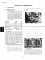
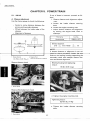
C. Draining coolant
1. When the coolant is still hot, slowly
loosen the radiator cap to lower the
pressure in the radiator. Take care not
to allow the coolant to spout out.
2. Remove the drain bolt on the exhaust
side of the cylinder, and let it run into a
container so that the cylinder head and
cylinder water jackets and radiator are
completely drained off.
A. Coolant level
WARNING:-----------.
Do not remove the rdiator cap when the
engine and radiator are hot.
Check the coolant level in the reservoir tank
when the engine is cold.
If the reservoir tank level is low. add coolant.
(Refer to D. Replenishing coolant).
Drain bolt tightening torque:
30 Nm (3.0 m-kg)
1. Reservoir tank
B. Coolant type
The coolant is a mixture of tap water and antifreeze. You may use an antifreeze sold in
the market. but the coolant should be prepared by taking into account the relation between the mixing ratio and freezing point.
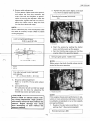
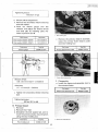
3. The coolant in the heat exchanger and
water pump located below the drain
bolt should be drained. To drain. remove
the by-pass pipe secured to the
thermostat housing by the clip, and hold
the by-pass pipe end facing downward.
Cooling system capacity:
2500 em'
When the mixing ratio of tap water to antifreeze is 1 1 (50% water 50% antifreeze).
the freezing point is -40°C (-40° F).
This mixture can be used in almost all
snowmobile conditions.
CAUTION:----------.
1) In an area where the temperature is
below -40°C (-40°F), the waterjantifreze mixing ratio should be 2 :
3 (40% water 60% antifreeze).
2) Do not use water containing impu rities 0 r oi I.
3-2
1980 SRX440
D. Replenishing coolant
4. After starting the engine, the coolant
level will go down. Add coolant while
keeping the engine running.
5. When the coolant level in the radiator
becomes stable, stop the engine.
Loosen (do not remove) the bleeder bolt
located above the thermostat va Ive
and let the air out. Add coolant to
radiator again up to the level line shown
in the illustration.
6. Repeat steps 4 and 5 above until the
coolant level in the radiator becomes
stable. Tighten bleeder bolt.
7. Start the engine and keep it running at
3,000 r/min until thermostat valve
opens. The thermostat valve opens at
60 ~ 65 0 C. If you look into the radiator, you can see when the valve opens,
that warm coolant will start flowing into
the radiator.
8. Add coolant until the reservoir tank is
NOTE: - - - - - - - - - -_ _
Before pouring the coolant into the radiator,
check the cooling system for damage, loose
joi nts or lea ks.
1. Loosen the air bleeder bolt.
1. Bleeder bolt
2.
Remove the radiator cap, and add coolant until the coolant begins to flow out
the air bleeder bolt hole (that is, all the
remaining air is forced out).
filled half The air remaining in the sys-
tem will be expelled through the radiator cap.
CAUTION:---------...,
Always check coolant level, and check
for coolant leakage before starting
engine.
3-2. COOLING SYSTEM CHECK
A. Cooling system check
1. Remove the radiator cap, and install a
pressure gauge.
3. Tighten the air bleeder bolt, and add the
coolant up to the specified level. Start
the engine.
,L
1. Coolant level
,I7J
-®
jr
2. Breather pipe
'3·3
1980 SRX440
2. Apply 10 bar (1.0 kg/cm 2 ) pressure. and
observe the gauge to check whether
pressure drops or not. If the pressure
shows a drop. the cooling system is
leaky. Repair as required. (Refer to "3-3
Radiator" or below.)
B. Inspection
1. In very dusty conditions, the radiator
tube system should be kept clean by
blowing through with compressed air
from the engine side.
2. Check the radiator for leakage and
damage. Repair as necessary.
3. Check the coolant hoses for cracks and
damage. Replace as required.
B. Radiator cap check
Using a pressure gauge. inspect the radiator
cap pressure and vacuum valve for spring
tension and seating condition. If the valve
opens at a pressure level below the specified
value or otherwise defective. replace the
radiator cap.
C. Installation
1. Install the radiator and coolant hoses.
2. Inspect the cooling system. (Refer to
"3-2-A Cooling system check"}
3. Fill with the coolant. (Refer to "3-2-0
Replenishing coolant")
3-4. HEAT EXCHANGER
.
A. Removal
1. Drain the coolant. (Refer to "3-1-C
Draining coolant")
2. Remove the slide rail suspension
to
"5-3
assembly.
(Refer
SUSPENSION".)
3. Remove the seat assembly.
4. Remove the coolant hoses and rivets
securing the heat exchanger.
Valve opening pressure:
8 ~ 10 bar (0.8 ~ 1.0 kg/cm 2 )
3-3. RADIATOR
A. Removal
1. Drain the coolant. (Refer to "3-1-C
Draining coolant"}
2. Remove the coolant hoses.
3. Remove the radiator stay bolts. and remove the radiator.
5. Remove the heat exchanger.
B. Inspection
Check the heat exchanger for cracks. broken
fins or leakage. Replace as required.
C. Installation
1. Secure the heat exchanger to the center
of the fra me with new rivets.
2. Install the coolant hoses.
3. Inspect the cooling system. (Refer to
"3-2-A Cooling system check"}
3-4
1980 SRX440D
4.
Install the seat and slide rail suspension
assembly.
(Refer
to
"5-3
SUSPENSION".)
5. Fill with the coolant. (Refer to "3-2-0
Replenishing coolant:")
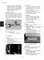
3-5. WATER PUMP
A. Disassembly
1. Drain the coolant. (Refer to "3-1-C
Draining coolant"}
2. Remove the water pump assembly from
the engine. (Refer to "2-1-0 Water
pump".)
3. Remove the water pump cover.
B. Inspection
1. Remove the deposits from the impeller
and water pump cover.
2. Check the impeller for cracks and
damage. Replace as required.
3. Check the oil seal and bearing for
damage and wear. Replace as required.
4. Check the water pump belt for damage
and wear. Replace as required.
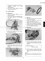
C. Reassembly
1. Coat the impeller shaft gear with grease.
4.
Remove the impeller nut. and remove
the impeller and collar.
2. Install the housing together with collar.
impeller shaft, driven water pump pulley
and belt.
5. Remove the housing, and remove the
impeller shaft. driven water pump pulley
and belt.
Tightening torque:
7 N m (0.7 m-kg)
3. Apply a grease to impeller shaft inside
the housing, and install the a-ring and
collar.
NOTE: - - - - - - - - - - -
----~-
Thoroughly wipe off the grease from the collar.
3·5
1980 SRX440
3. Remove the thermostat.
4. Install the impeller.
B, Inspection
1. Suspend thermostat in a vessel of water
with a reliable thermometer.
2. Heat the water slowly, noting the
thermometer reading and stirring the
water continually.
3. The thermostat valve should begin to
open at 60 ~ 65°C (140 ~ 149° F),
Tightening torque:
25 Nm (2.5 m-kg)
5. Coat the mating surfaces of water pump
housing and cover with YAMAHA
BOND #4, and install a new gasket.
6. Install the water pump cover.
TightEiriirig torque:
7 Nm (0.7 m-kg)
-G)
so-c 1176' FI
60
65°C
114G'~ 149'FI
7. Install the water pump assembly on
the engine, and adjust the belt tension.
(Refer to "2-2- F Water purnp'")
8. Inspect the cooling system. (Refer to
"3-2-A Cooling system check")
9. Fill with the coolant. (Refer to "3-2-0
Replenishing coolant"}
0
-®
,,",
-rID
¢ 0
1. Thermometer
2. Full open
,3. Begin to open
3-6, THERMOSTAT
i
0 0
4. Water
5. Thermostat
6. Vessel
NOTE: - - - - - - - - - - - Thermostats are sealed and their setting is
specialized work. Always replace if doubt exists. A faulty unit could cause serious
overheating.
A, Removal
1. Drain coolant to below thermostat level
by loosening cylinder drain bolt.
2. Remove the coolant hose and the
thermostat cover.
C, Installation
1. Install the thermostat and cover.
Tightening torque:
7 Nm (0,7 m-kg)
3-6
1980 SRX440
2. Install the coolant hose.
3. Inspect the cooling system. (Refer to
"3-2-A Cooling system check:")
4. Fill with the coolant. (Refer to "3-2-0
Replenishing coolant")
3-7
1980 SRX440D
CHAPTER 4. CARBURETION
4-1.
4-2.
CARBURETOR
A. Carburetor tuning
B. Overhauling
C. Troubleshooting
FUEL PUMP
,
4-2
4-2
4-5
.4-10
4-12
1980 SRX440
CHAPTER 4. CARBURETION
4-1. CARBURETOR
Free play between outer tube end and
adjuster:
0.5 ~ 1.0 mm (0.2 ~ 0.4 in)
A. Carburetor tuning
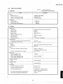
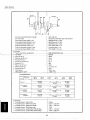
1. Standard specification
The carburetor is set at the factory to
run at temperatures of O°C to - 20°C
(32 ° F to - 4 ° F) at sea level. If the
machine has to be operated under conditions other than specified above, the
carburetor must be reset as required.
Special care should be taken in carburetor setting so that pistons will not be
holded or seized.
Main jet
#260
Power jet
#115
Pilot jet
#85
Pilot screw
2.0 turns out
Starter iet
"Hoet height
Idling engine speed
1. Outer wire
2. Adjuster
3. lock nut
b. Remove the intake air silencer, and pull
the throttle lever while lookin into the
bores of both the right and left carburetors. Set the throttle cable adjuster SO
that both throttle valves to open at the
same time.
Also make certain that the throttle
valves reach full throttle position at the
same time.
c. Repeat the operation specified in a. and
b. above. When the adjustment is complete, be sure to install the intake air
silencer.
160
30 ± 1 mm
11.18 ± 0.04 in)
1.500 r/rntn
CAUTION:----------,
If the air silencer box is removed from
the carburetors. the change in intake
pressure will create a LEAN MIXTURE
that may result in severe engine
damage. The air silence box has no
effect on performance characteristics
and it must be secured to the carburetor
during carb tuning and adjustment. It
must always be in place when the
engine is operated. Examine the
silencer regularly for cleanliness and
freedom from obstruction,
2. Throttle cable and throttle valve opening
a. Set the throttle cable adjuster so that
the free play between the throttle cable
outer tube end and adjuster when the
throttle is closed (idling) as specified
below:
·1. Check to see synchronising
WARNING:----------,
Throttle cable must not be lubricated in
any way. It must be routed correctly to
avoid throttle problems that may lead to
an unsafe condition during operation.
4-2
1980 SRX440
3. Starter cable adjustment
Pull the starter cable outer tube upward,
and adjust the free play between the
outer tube end and adjuster to specification by turning the adjuster. After the
adjustment, tighten the lock nut and replace the rubber cap to keep the lock
nut free from dust and water.
a. Tighten the pilot screw lightly, and back
it out from its lightly seated position.
Standard pilot screw (turns out):
2.0
NOTE: -----------~
Starter cable free play must be adjusted after
the cable is correctly routed. (Refer to Cable
routing diagram.)
Lock nut tightening torque:
0.08 m-kg (0.6 ft-Ib)
1. Pilot screw
2
b. Start the engine by pulling the starter
lever, and fully warm up the engine.
c. Set the throttle stop screw so that the
CD
Idling engine speed: 1,500 r/min
'.5""'" 2.5 mm (0.06 ':" 0.' 0 in)
NOTE: - - - - - - - - - - - Make certain that both throttle valves are adjusted to the same opening.
1. Adjuster
2. Lock nut
Free play between outer tube end
and adjuster:
15 ~ 2.5 mm (0.06 ~ 0.10 in)
4. Oil pump cable adjustment
Refer to "2-2-8-5. Pump cable adjustment",
5. Low speed tuning
The carburetor is built so that low speed
tuning can be done by adjusting the
throttle stop screw and pilot screw.
1. Throttle stop screw
NOTE:-----~-----
CAUTlON:-----------.
Always install air silencer before making tuning adjustment, High performance tuning cannot be done without the
silencer. Engine damage may result
from attempting to tune without the
silencer installed,
If the engine shows poor performance in elevation or in an extremely cold area or when it
is suddenly accelerated or run at low speeds,
proceed as follows:
1. Replace the pilot jets according to "Jet
setting chart" (See next paragraph).
Standard pilot jet: #85
4-3
1980 SRX440D
Spare pilot jet:
2. Turn the pilot screw in and out 1/4 turn
or less each time, and set it in a position
where the engine idles faster.
3. Follow step C in the preceding paragraph.
#90, #80
6. Main circuit tuning
No adjustment is normally required, but
adjustment is sometimes necessary depending on temperatures and/or altitude. (Refer to Jet setting chart.)
1. Pilot jet
Temperature
Altitude
-30°C
(-22°FI
Sealevel
Up to 1000 m
13000 It)
Up to 2000 m
16000 It)
Up to 3000 m
110000 It I
-20°C
(-4°F)
-10°C
aOc
(14°FI
(32 OF)
10°C
150°F)
MJ #260
PJ #85
- M J # 2501~~
PJ#85
MJ #240
PJ # 85
MJ #240
PJ#85
-MJ#230--PJ #85
MJ #220
PJ #85
MJ #210
PJ#95
-MJ#200-~
MJ #190
PJ #95
MJ #180
PJ#105
-MJ#170-~
PJ#95
PJ #105
a. Run the engine at high speeds, and
make sure the engine operates smoothly.
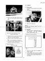
b. Check both spark plugs and, depending
on the discoloration of each spark plug,
the main jet should be adjusted on the
basis of the following table. (Refer to
spark plug color samples.)
MJ #160
PJ #1 05
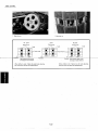
Spark plug color
No.1
Good (Carburetor is tuned properly.)
Bad (Mixture is too rich.)
NO.2
Replace main jet with one-step
smaller one.
Bad (Mixture is too lean.)
No.3
Replace main jet with one-step
larger one.
Bad (Due to too lean a mixture. piston
Standard main jet:
is holed or seized.]
#260
No.4
Replace the piston and spark plug.
Tune the carburetor again, starting
with low-seed tuning.
Spare main jet:
Bad (Due to too lean a mixture. the
engine knocks.)
#270,#250,#240,#230
No.5
Check the piston for holes or seizure.
Check the cooling system. gasoline
octane rating and ignition timing. After
replacing the spark plug. tune the
carburetor again. starting with
low-speed tuning.
4-4
1980 SRX440
Bad (Due to lean a mixture. the spark
pluq melts.)
No.6
Check the piston for holes or seizure.
Check the cooling system, gasoline
octane rating and ignition timing. After
replacing the spark plug with colder
type, tune the carburetor again.
starting with low-speed tuning.
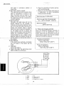
1. Throttle cable
2. Pump cable
3. Starter cable
CAUTION: - - - - - - - - - ,
When removing the starter cable, take
care so that the rubber cap, coil spring
and starter cable do not fall off or are
not lost. A lso use specia I ca re not to
scratch the rubber seat su rface.
1. Main jet
WARNING:--------~
c. Float chamber
emove e our screws,
the float chamber.
2) Remove the main jet
together with the O-ring.
while the engine is hot, Fuel will flow
out of the float chamber which could ignite and cause damage to the
snowmobile and possible injury to the
mechanic.
Place a rag under the carburetor so fuel
does not spread. Place the main jet
cover bolt in a clean place. Keep away
from fire. After assembling the carburetor, firmly tighten the rubber joint screw.
Make sure the throttle outer tube is in
place and the throttle cable moves
smoothly. Clean the carburetor and
allow it to dry.
B. Overhauling
d. Carburetor body
1) Remove the arm pin, together with the
float assembly.
2) Remove the pilot jet and main jet.
3) Remove the main nozzle.
4) Remove the valve seat assembly.
5) Remove the power jet.
6) Remove the pilot screw, together with
the coil spring.
7) Remove the throttle stop screws,
together with the coil spring.
1. Disassembly
a. Remove the intake. silencer assembly.
b. Remove the carburetor from the
engine, and disconnect the control
cables as follows:
1) Loosen the throttle cable holder screw.
2) Remove the pump cable adjuster from
the stay plate. and remove the pump
cable from the lever.
3) Remove the cap from the carburetor.
together with the starter valve, and disconnect the starter cable.
4·5
1980 SRX440
NOTE:-----------1. Hook the clip onto the float arm. and
remove the fuel valve while taking care
not to drop it .
.2. The fuel valve plays a very important
role. so special care should be taken so
that the rubber part of the needle is not
scratched.
3. Use care to keep the plastic parts free
from shocks. because they could be
. damaged easily.
4. Never wash the rubber parts with alcohol or lacquer thinner. Use gasoline.
4-6
1980 SRX440
2. Inspection
CAUTION: - - - - - - - - - - ,
Never attempt to disassemble the following parts.
1) Throttle valve
2) Throttle shaft
Reason:
1) The threaded portion of the screw is
clinched after the throttle valve is installed to the throttle shaft so that
the screw will not come loose.
2) The bypass hole is precrsronmachined so that the correct distance can be maintained from the
end of the throttle valve. Therefore,
if the throttle valve is once disassembled, it is difficult to reproduce
the original dimensions, and thus
engine performance will be adverselyaffected.
-CAUTION: - - - - - - - - - - ,
1) Before checking, thoroughly clean
all parts in gasoline, and blow the
jets, float chamber and fuel passages in the carburetor body with
compressed air so the dust and dirt
can be removed.
2) When washing the carburetor body
and float chamber, be sure to use a
soft brush.
3) When decarbonizing the throttle
valve and its adjacent area, take
special care not to scratch the throttle valve and throttle bore.
4) Never use a hard wire or the like
when cleaning jets. It could scratch
or deformed jet holes, thus adversely
affecting fuel consumption.
5) Use care so that all parts are not deformed.
'l . Power jet
2. Starter circuit
3. Main air jet
4. Slow air jet
5. Main jet
6. Jet nozzle
7. Slow jet nozzle
8. Pjlot jet
9. Starter jet (Body jet)
®
4-7
1980 SRX440
a. Float chamber
1) Check the starter jet and power jet
circuits for clogging with dust. If clogged. blow them off with compressed air.
3) Check the starter circuit for clogging
with dust. If clogged, blow if off with
compressed air.
NOTE: -------~_-~-
If the starter circuit is clogged, fuel flow will
be hindered and hard starting will result.
4) Blow the air bent and slow circuits with
compressed air.
1. Starter jet circuit
2
Power jet circuit
2) Blow the float chamber clean of dust
and dirt with compressied air.
b. Carburetor body
1) Clean the fuel valve seat while taking
care not to scratch the seat, and blow
it with compressed air.
Check the end of the valve needle and
the valve seat for damage.
If damaged, replace the valve needle
and valve seat as an assembly.
Pe .. erjet eiletlit
Starter jet circuit
Slow circuit
5) Blow the starter circuit, main air jet
and pilot air jet with compressed air.
1. Starter circuit
2. Main air jet
3. Pilot air jet
6) Blow the main jet, pilot jet. power jet
and main nozzle with compressed air.
7) Blow the pilot screw clean of dust and
dirt with compressed air.
8) Check the end of pilot screw for carbon.
Check the tapered portion and threaded
portion for damage.
AUTlON: - - - - - - - - - ,
A scratched seat could result in the
overflow of fuel.
2) Check the power jet circuit for clogging.
If clogged, blow it with compressed air.
NOTE: - ~ - - - - - - - - -
If this circuit is clogged, engine power loss
will result at high speed operation.
4-8
1980 SRX440
NOTE: - - - - - - - - - - - - The pilot screw must not be tightened excessively.
51 Install the valve seat.
Tightening torque:
5 Nm (0.5 m-kg)
6) Put the valve needle into the valve seat.
NOTE: - - - - ' - - - - - - - - - - After assembling. take care not to allow dust
and dirt to enter.
3. Reassembly and adjustment
CAUTION:-----------,
1) Wash all parts in clean gasoline be-
fore assembling.
7) Float level
(1) Reinstall components. except for
2) Always use new a-rings.
Make sure moving parts rotate or
slide smoothly.
4) Apply grease to contact surfaces of
the throttle shaft.
3)
(2)
the float chamber.
Incline the carburetor at 20 ~ 30°
(so that the end of the float valve
weight), and measure the distance
from the mating suface of the float
chamber and carburetor to the top
of the float using a gauge.
a. Carburetor body
1) Install the main nozzle. main jet. and
pilot jet.
Float level:
30 ± 1 mm (1.18
Tightening torque:
Main nozzle: 5 Nm (0.5 m-kg)
Main jet:
2 Nm (0.2 m-kg)
0.8 Nm (0.08 m-kg)
Pilot jet:
.
± 0.04 in)
.
NOTE:-----------~
.
The float should be just resting on. but not
depressing the spring loaded inlet needle.
2) Install the power jet and power jet cover
bolt.
Tightening torque:
Power jet:
1.8. Nm (0.18 m-kg)
Power jet cover bolt:
4 Nm (0.4 m-kg)
3) Install the throttle stop screw and coil
spring.
Adjustment: See" Low speed tuning."
4) Install the pilot screw and coil spring.
Adjustment: See" Low speed tuning."
1. Float level
(3)
4-9
If the float level is not within the
specified range. check the valve
seat and needle valve. And replace
any damaged part.
1980 SRX440
(4)
If any part is in good condition but
float level is not within the
specified range, correct float level
by bending the float arm tang
slightly.
r:CAUTION:
(Always use a new O-ring for reassembly.
I
c. Push the carburetor into the rubber joint,
and secure it with the band.
1) Before installing the carburetor on the
engine, connect the control cables in
the reverse order of disconnection.
Keep the starter valve free from dust
and dirt during this operation.
2) Insert the end of throttle cable into the
hole in the throttle lever. adjust the play
of cable. and secure it with screw. (See
"Throttle cable adjustment.")
NOTE:------------By turning the throttle lever to the full-open
position two or three times, make sure it operates correctly.
CAUTION: - - - - - - - - - ,
After installing the carburetor body, be
sure to apply grease to the following
parts as an anti-freeze measure:
3) Make sure the starter lever isfullv pushed in. and connect the starter cable
and spring to the starter valve. and install the valve in the carburetor.
Adjust the starter cable. (See "Starter
cable adjustment.")
Recommended low
temperature grease:
ESSO Beacon 325 or
Aero Shell #7
Tightening torque:
3.5 Nm (0.35 m-kg)
1) Throttle return spring, throttle shaft
collar.
2) Space between carburetor body and
throttle shaft (at 2 places),
3) Throttle lock washer, E-clip.
4) Wire holder attached to the throttle
valve.
NOTE: - - - - - - - - - - - By pulling the starter lever two or three times
after installation of the starter cable. check
the operation of the starter valve.
4) Install the fuel pipe to the carburetor.
Next. install the clip firmly.
d. Install the intake silencer.
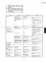
C. Troubleshooting
This troubleshooting guide relates only to the
carburetor. Making an adjustment of the
carburetor. check the engine and electrical
system. If no defect is found, consult this
troubleshooting guide.
b. Float chamber
1) Screw the main jet cover bolt (with O-ring) into the float chamber.
2) Install the O-ring to the float chamber,
and install it to the carburetor body.
~
CA U TI O N :
1) When disassembling the carburetor,
use care so that parts don't fall off or
are not lost. Also don't strike the
4·10
1980 SRX440
carburetor with a hard tool. Dust
should be blown off with compressed air.
2) When reinstalling the throttle cable,
make su re the th rottle va Ive can be
fully opened and closed, and make
an adjustment.
Trouble
Check point
Hard starting
Remedy
Insufficient fuel
Add gasoline
Excessive use of starter
Clean spark plug
(Excessively opened choke)
Fuel passage is clogged or
frozen
frozen
Adjustment
Return starter lever to its home
position.
Clean
Parts other than carburetor
Clogged fuel tank air vent. clogged
fuel filter. or clogged fuel passage
Carburetor
Clogged or frozen air vent clogged
valve
If water collects in float chamber.
clean
(Also check for ice.)
Overflow
Correct
adjustment
(Relative troubles)
Pilot screw adjustment
See "Overflow
.
throttle opening. If incorrect. back it
Adjust idling speed
Poor performance at low
speeds
Poor acceleration
out specification. Start the engine
and turn pilot screw in and out
1/4 turn each time. When the engine
runs faster. back out throttle stop
screw so the engine idles at
Slow response to throttle
Engine tends to stall
Throttle stop screw
Adjust
specified speed.
Tightened to much-Engine speed
is higher.
Backed out too much-Engine does
no idle.
-
Poor performance at
mid-range speeds
(Relative troubles)
Damaged pilot screw
Replace pilot screw
Clogged bypass hole
Clean
Clogged or loose slow jet
Clean and retighten
Air leaking into carburetor joint
Defective starter valve seat
Retighten band screw
Clean or replace
Overflow
Correct
Clogged or loose slow jet
Clean and retighten
Remove slow jet. and blow it out
with compressed air.
See "Overflow. "
Remove slow jet, and blow it out
with compressed air.
Momentary slow response
to throttle
Poor acceleration
Poor performance at normal
speeds
(Relative troubles)
Excess fuel consumption
Poor acceleration
Poor performance at high
speeds
(Relative trouble)
Lean mixtures
Overhaul carburetor
See "Overflow. "
Clogged air vent
Clean
Remove the air vent pipe.
and clean.
Clogged or loose main jet
Clean and retighten
Remove main jet and blow it out
with compressed air.
Overflow
Check float and float valve
and clean
See "Overflow "
Starter valve is left open
Fully close valve
Return starter lever to its home
position
Power loss
Poor acceleration
Clogged air vent
Remove and clean
Clogged or loose main jet"
Clean and retighten
.-
4-11
Remove main jet. and clean with
compressed air. then install.
•
..
··
1980 SRX440
Trouble
Abnormal combustion
(Mainly backfire)
Overflow
(Relative troubles)
Power idleing
Clogged power jet
Clean
Clogged fuel pipe
Clean or replace
Dirty fuel tank
Clean fuel tank
Air leaking into fuel line
Check joint and retighten
low fuel pump performance
Repair pump or replace
Clogged fuel filter
Replace
Clogged silencer outlet
Check for ice. and remove
lean mixtures
Clean carburetor and adjust
Dirty carburetor
Clean carburetor
Dirty or clogged fuel pipe
Clean or replace fuel pipe
Clogged air vent
Clean
Clogged float valve
Disassemble and clean
Power loss
Poor acceleration
Scratched or unevenly worn
float valve or valve seat
Clean or replace float valve
and valve seat
Valve seat is press-fitted to body.
So body must be replaced if seat is
damaged.
Broken float
Replace float
Incorrect float level
If not within the specified
• Worn float tang
• Worn arm pin
.
Clean while taking care not to
scratch valve seat
Poor performance at low.
mid-range. and high
speeds
Excessive fuel consumption
Hard starting
Adjustment
Remedy
Check point
• uerormeo ttoat arm
range. check the following parts
and replace any defective part
Replace float
Replace arm pin
aeotece neat
4-2. FUEL PUMP
Check to see if fuel moves from tank to
carburetor. and if any fuel leaks from pipe
joints or fuel pump body.
Replace fuel pump assembly as required.
1. Fuel pump
4-12
Replace float assembly.
1980 SRX440
CHAPTER 5. POWER TRAIN
5-1.
5-2.
5-3.
5-4.
DRIVE
5-2
A.
Sheave adjustment
5-2
B.
Primary sheave
C.
V-belt..
5-7
D.
Secondary sheave
5-7
E.
Chain housing
5-9
F.
Front axle
:
5-3
5-13
BRAKE
5-15
A.
Disassembly
5-15
B.
Inspection
5-15
C.
Reassembly
5-16
D.
Adjustment.
5-16
SUSPENSION
5-16
A.
Removal.............................................................................................................. -16
B.
Inspection
:
5-17
C.
Slide rail suspension adjustment..
5-18
D.
Installation
5-20
DRIVE TRACK
5_20
A.
Removal
5-20
B.
Inspection
5 -20
C.
Installation
5 -21
D.
Adjustment
5 -21
1980 SRX440
CHAPTER 5. POWER TRAIN
If any of these is incorrect. proceed as follows:
1. Sheave distance and alignment adjustment
a. Loosen the intake silencer securing
bolts.
b. Loosen the engine mounting nuts.
c. Adjust sheave distance and alignment
by moving the engine back. forth or
sideways.
5-1. DRIVE
A. Sheave adjustment
Use the sheave gauge to check the following:
Center to center distance between the
primary and secondary sheaves.
Off-set between the inside edge of the
sheaves.
Alignment of sheaves.
.
.
Tool name
Tool No.
Sheave gauge
90890-01875
.
Sheave distance:
270 ~~ mm (10.63
+0
-0.11
in)
NOTE: ------~----
If sheave distance or alignment is not ad-
1. Sheave distance
+0
+O.
270 -3 mm (10.63 _O.11m)
2. Sheave off-set
5.5 ± 0.5 mm (0217
± 0.020 in)
Sheave distance check
bolts on the bearing housing supporting the
secondary shaft and readjust sheave distance and sheave alignment.
Bearing housing-bolt tightening
torque:
65 Nm (6.5 m-kg)
1. Sheave gauge
Sheave offset/alignment check
d. Tighten the engine mounting nuts.
Tightening torque:
52 Nm (5.2 m-kg)
e. Tighten the intake silencer securing
bolts.
1. Sheave gauge
5-2
1980 SRX440
Tightening torque:
7 Nm (0.7 m-kg)
2. Sheave off-set adjustment
a. Remove the secondary sheave securing
bolt and washer.
b. Place the sheave gauge over the
sheaves, and adjust the sheave off-set
and axial play by installing plate washers at points A and B.
1. Rotor holding tool
Thickness
Parts name
Plate washer 190201-25526)
2 mm 10.08 in)
Plate washer 190201-25527)
1 mm 10.04 in)
c. Remove the primary sheave assembly,
using the primary fixed sheave puller
and rotor holding tool.
Tool name
Tool No.
Tool name
Tool No:
Sheave gauge
90890-01875
Primary fixed sheave puller
90890-01859
'l . Primary fixed sheave puller
Sheave off-set:
5.5
2. Disassembly
a. Install the sheave sub-assembly tool to
the primary sheave.
± 0.5 mm (0.217 ± 0.020 in)
Axial play:
o ~ 1.0 mm (0
~
0.04 in)
Tool name
Tool No.
Sheave sub-assembly tool
90890-01858
c. Tighten the secondary sheave securing
bolt.
Tightening torque:
50 Nm (5.0 m-kg)
B. Primary sheave
1. Removal
a. Remove the V-belt..
b. Straighten the lock washer tab, and remove the primary sheave mounting bolt,
using the rotor holding tool.
.
Tool name
Tool No.
Rotor holding tool
90890-01235
.
1. Sheave sub-assembly tool
5-3
1980 SRX440
b. Loosen the six bolts securing the
primary sheave cap and sliding sheave.
c. Remove the sheave subassembly tool.
The primary sheave cap and sliding
sheave can now be disassembled.
3. Inspection
a. Check the tapered ends of the crankshaft and primary fixed sheave for
scratches. If scratched unduly. replace.
If scratches are minor. burnish with
emery cloth.
b. Check the primary sheave cap bushing
and sliding sheave bushing for wear. If
beyond tolerance. replace the bushing.
NOTE:-----------If bushing is installed tightly. remove the bushing using the bushing tool.
Tool name
Bushing tool
90890-01877
Bushing clearance. limit
~
Small bushing
Large bushing
Inside
0.25 mm (0.01 in)
0.25 mm (0.01 in)
Outside
0.25 mm (0.01 in)
0.25 mm (0.01 in)
1. Bushing too!
c. Check the compression spring for
igue. ex es ive y
igue. rep
d. Check the spider and roller for smooth
movement and wear.
e. Check both sheaves for warping. If
warped. replace.
4. Adjustment
The primary sheave tuning should .be
set according to the altitude.
5-4
1980 SRX440
Altitude
Setting parts
Sea level (Std.)
(Upto 1500 m (5000 It))
High altitude
(About 1500 m (5000 It) or morel
90501-60579
90501-55296
Red-Brown
Green-Pink
39 kg
55 kg
2.85 kg/mm
1.75 kg/mm
90251-06015
e-.
Parts No.
Color code
Spring
Set load
Spring constant
Parts No.
0
0
Counter sunk
rivet
Set holes
0
e
e
0
[0
NOTE:------------On the sea level (Up to 1500 rn). if engine
power is poor with snow condition, adjust
sheave at the high elevation setting.
o
a. Cornpressionsprinj;
Clutch engagement rpm must be adjusted to specification using an optional
compression spring.
b. By changing the position and quantity
of primary weight rivets, the thrust of
weight can be changed, and thus the
engine rpm at which the clutch is
shifted can also be changed. (As a result, the engine rpm at which the clutch
is engaged can be changed.)
5. Reassembly
a. Adjust the slider button-to-quide clearance by the shims under the each
slider button.
CAUTION: - - - - - - - - - - - ,
The rivets for three weights must be in
the corresponding positions. -
Slider button-to-guide clearance:
~ 0.2 mm (0 ~ 0.008 in)
o
Shim (90201-090A4)
Rivet
Shifting rpm
rpm
increases.
No rivet is in use
CD
®
No rivet
Thickness
0.3 mm (0.012 in)
CAUTION:----------,
The shims for three parts must be in the
corresponding positions.
CD®
rpm
decreases.
5-5
1980 SRX440
c. Install the component parts to the sliding sheave and the sheave cap.
Slider button-toShim
guide clearance
NOTE: - - - - - - - - - - - 1. When installing the spider and primary
sheave cap to the primary sliding
sheave, be sure to align the X marks on
the spider and sheave cap with that on
sliding sheave.
b. Oil the points shown in the illustration.
Do not apply the grease on the portion
of X mark. For other parts. greasing is
unnecessary.
2. when installing the spacer and collar to
the spider. the spacer and the spider
projections must be fitted to the collar
slit.
_
X Free from oil
Greasing point
CAUTION:---------...,
When the bushing is replaced with new
one. apply molybdnum disulfide grease
to bushing lightly. Except for this. Don't
grease.
CAUTION:---------...,
If the cotter pin. is removed for the
greasing. replace it with new one.
o
5-6
1980 SRX440
d. Install the sheave subassembly tool and
tighten the cap.
e. Tighten the six primary sheave cap bolts
and remove the subassembly tool.
Tightening torque:
11 Nm (1.1 m-kg)
C A U T I O N : - - - - - - - - -.....
Make sure that the primary sheave cap
assembly slides in contact with the
fixed sheave boss.
Tightening torque:
First tighten the bolt to a torque of
A. then loosen it.
Retighten bolt to a final torque of B.
A: 120 Nm (12 m-kg)
B: 65 Nm (6.5 m-kg)
.
C. V-belt
Check the drive V-belt for damage and wear.
If the width is less than specified value. replace with a new belt.
Wear limit: 26 mm (1.02 in)
f. Clean the oil off the tapered portion of
crankshaft using a lacquer thinner.
g. Fit the primary sheave assembly to the
tapered portion of crankshaft.
h. Apply engine oil to the threaded portion
of primary sheave bolt and its contact
surface with spring washer.
rr==~@
\
I
!
\
\
I
\
I
I
I
\
\
\
I
\
\
I
\
\
\
I
I
I
! I
1. New: 31.5mmll.24inl
2. Wear limit: 26 mm (1.02 in)
D. Secondary sheave
1. Disassembly
a. Apply the brake and remove the secondary sheave mounting bolt.
b. Remove
the
secondary
sheave
assembly and plate washers.
i. Tighten the primary sheave mounting
bolt. using the rotor holding tool. Next.
lock the lock washer.
NOTE:-----------Check the lock washer, and if damaged. replace with a new one.
5-7
1980 SRX440
c. Remove the circlip and disassemble the
secondary sheave component parts.
b. Check torsion spring for fatigue. If excessively fatigued, replace.
c. Check both sheaves for warpage. If
warped replace.
3. Secondary sheave spring adjustment
It is advisable to change the secondary
sheave setting to correspond to the
course and snow conditions. This is
done by changing the secondary spring
preload.
as
e spring sea see I ustratron
spring holes. The spring tension
(preload) can be adjusted by selecting a
spring in the seat and twisting the seat
to engage the sheave ramps. In this way
the preload can be adjusted in 30 0
steps.
2. Inspection
a. Check the ramp shoes on secondary
sliding sheave for wear. Replace ramp
shoes as required.
[Secondary spring setting]
Course
Trail and tour
Lake surface
Position of spring seat
Twist
Position of spring seat
Twist
Ice snow
Std.
Std.
No.2
60 0
Packed snow
Std.
Std.
Std. or No.2
Std. or 60°
Std. or No.4
Std. or 120
Std.
Std.
Setting factor
Wet snow
0
Std. secondary spring:
PIN: 90508-45286
Color code: Yellow
Std. secondary spring position:
No.3
Std. secondary spring twist:
90 0
a. Secondary spring position
The spring seat is provided with four
holes, Nos. 1 to 4, so that the secondary
spring position can be changed as required.
A. Spring seat
5-8
1980 SRX440
b. Secondary spring tension
The secondary spring tension can be
changed by moving the spring position
from the free position in order to reset
the clutch shifting RPM as required. The
four holes are spaced at intervals of 30°.
Secondary spring
position
d. Install the secondary sheave assembly
and adjust the axial play and sheave off
set.
(Refer to 5-1-A-2. "Sheave off set adjustment")
Spring wind
No.1
30°. 150°.270°
No.2
60°.180°
No.3
90°.210°
No.4
NOTE:-----------After installation, thoroughly clean both fixed
and sliding sheaves so that they are free of
oil.
e. Tighten the secondary sheave mounting
bolt.
0°.120°.240°
Tightening torque:
50 Nm (5.0 m-kg)
Winding the spring more (e.q.. from 30°
to 60°) will increase the clutch shifting
rpm and vise versa. Snow conditions
will also require a change of the spring
tension in order to attain the standard
shifting rpm. The spring tension must be
greater on wet snow than on packed
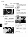
E. Chain housing
1. Disassembly
a. Remove' the chain housing cap and
drain the chain housing oil.
snow.
4. Reassembly
a. Grease the sliding sheave boss and secondary shaft. and mount the sliding
sheave on the shaft.
Recommended grease:
Molybdenum disulfide snowmobile
grease
b. Apply the brake and remove the drive
sprocket nut and driven sprocket bolt.
b. Install the sliding sheave to the fixed
sheave. and set the spring and spring
seat as specified. (See "Secondary
sheave spring adjustment" of above
item)
c. Install the circlip secondary fixed sheave
boss slit.
5-9
1980 SRX440
f. After removing the suspension assembly, remove the four bolts mounting the
chain housing. (Refer to 5-3. Suspension)
c. Loosen the chain tensioner and remove
the drive, driven sprockets and chain.
d. Remove the bearing inner race securing
screw, and loosen the inner race by
using eccentric bearing installer.
Tool name
Tool No.
Eccentric bearing installer
90890-01851
g. Remove the chain housing assembly.
h. Remove the secondary shaft complete.
/. Remove the bearing race and brake disc
and key.
1. Eccentric bearing installer
2. Inspection
a. Drive chain
Except in case of oil starvation, the
chain wears very little. If the chain has
stretched excessively and it is difficult
to keep the proper chain tension, the
chain should be replaced.
b. Drive, driven and
chain
tension
sprockets.
Check sprocket for obvious wear. Replace sprocket as required.
c. Bearing and oil seals
Check the chain case bearings and oil
seals for damage. If damaged, replace.
3. Gearing selection
The reduction ratio of driven sprocket to
drive sprocket must be set according to
the snow condition.
e. Remove the brake caliper assembly.
(Refer to 5-2. "Brake section")
5-10
1980 SRX440
Many rough surfaces or unfavorable
snow conditions; the driven/drive
sprocket ratio should be made larger.
Few rough surfaces or better snow conditions; the ratio should be made smaller.
a. Std. reduction ratios
Drive chain sprocket
18 (P!N 878-17682-80)
Driven chain sprocket
29 (P!N 878-47648-90)
Chain (Links)
70 (P!N 94860-36070)
b. A guide to reduction ratios
Trail riding
ICY
Packed
Wet
ICY
Packed
Wet
ICY
Packed
Wet
Drive chain sprocket
Std.
Std.
17
Std.
Std.
17 or
Std.
16
16
16
Driven chain sprocket
Std.
Std.
Std.
Std.
Std.
Std.
33
33
33
Chain (links)
Std.
Std.
Std.
Std.
Std.
Std.
Std.
Std.
Std.
. Snow condition
c. Sprocket ratio and chain link chart
The following sprockets, drive and
driven, and chains are available as options. The figures in upper lines repre-
......
•••••
Hiqh altitude
(Up to 1500 m or more)
Lake course
."-.......
Teeth of drive
~
Teeth of
driven sprocket
15
P/N878.
16
P/N878-,
17682-50
17682~60
17
piN 878.
17682-70
19
18
PIN 87817682-90
(SRX440
Std.)
20
P/N878.
22
21
17693"00
P/NoBl8"_
17693-10
1.450
70
_70 or 72
P!N,878~
17693-20
29
'.933
1.813
1.706
1.611
1.526
(SRX440 Std.)
68
68 or 70
70
31
2,067
1.824
1.722
70
1.632
70
70
70 or 72
72
72
72
1.941
70 or 72
1.833
72
1.737
1.650
1.571
1.500
72
74
1.944
1.842
1.667
72 or 74
72 or 74
72
1.750
74
72 or 74
2.059
72
1.591
74 or 76
PIN 878-47587-00
68
68
1.938
70
33
2.200
2.063
PIN 888-47587-00
70
2.333
72
2.188
35
PIN 878-47587-20
.
sent the driven/drive sprocket ratios,
while those in lower lines represent the
number of chain links.
70
72
Chain links
Parts No.
68
94850-36068
72
94850-35072
74
1.550
1.381
1.476
74 or 76
1.318
72
1,409
Tightening torque:
23 Nm (2.3 m-kg)
94850-35074
-:
4. Reassembly
a. Apply a low temperature grease to the
chain housing oil seal lip. Install the secondary shaft complete with brake disc.
NOTE:-----------Make sure woodruff key is properly seated in
key way of secondary shaft. Install brake disc
so that it is aligned with the woodruff key.
c. Install the brake caliper assembly.
b. Use the four bolts to mount the chain
housing to frame.
Brake caliper mounting bolt
tightening torque:
50 Nm (5.0 m-kg)
.
5-11
..
1980 SRX440
d. Install the drive and driven sprockets
with chain.
Place the collar into the drive sprocket.
Tighten the drive sprocket nut and
driven sprocket bolt. and install a new
cotter pin on the secondary shaft.
Tightening torque:
Drive sprocket nut:
50 Nm (5.0 m-kg)
Driven sprocket bolt:
50 Nm (5.0 m-kg)
1. Oil level screw
Fill until oil begins to run out the screw
hole.
Recommended oil:
Gear oil API "GL-3"
SAE #75 or #80
Quantity: 320 em'
After adding oil. be sure to install and
g. Chain tension adjustment
Remove adjuster bolt clip. Tighten adjuster bolt (turn clockwise) by hand
until nearly tight. Then tighten or loosen
slightly to align clip hole with clip stopper. Install clip.
e. Install the chain housing gasket and
chain housing cap.
NOTE:-----~----____,____
Check the gasket. and if damaged. replace
with a new one.
Tightening torque:
16 Nm (1.6 m-kg)
f. To add gear oil. the filler cap and oil
level screw should be removed.
1. Adjusting bolt
h. Tighten the bearing inner race by using
eccentric bearing installer.
1980 SRX440
1. Eccentric bearing installer
I.
d. Remove the chain housing cap.
(Refer to "chain housing".) Drain oil and
remove the chain driven sprocket.
e. Loosen the left side guide wheel securing collar and slide the guide wheel to
the right side.
Tighten the bearing inner race securing
screw.
Tightening torque:
6 Nm (0.6 m-kg)
1',
f. Pullout the front axle.
Front axle
1. Removal
a. Remove the slide rail suspension
assembly.
(See 5-3. Suspension)
b. Remove the speedometer gear housing.
g. To remove the wheel sprocket from the
axle. loosen the band and push out
using a press.
2. Inspection
Check wheel sprocket for damage and
wear. Replace wheel sprocket as required.
c. Remove the nut mounting the front axle
and front axle housing. (Lock the front
axle by applying the brake.)
5-13
1980 SRX440
3. Insta lIation
a. When installing the wheel sprocket to
the front axle. position the wheel
sprockets on the front axle as shown.
Use a press.
I
29.6mm
'(1.17ini
46mm
(1,81 in)
57mm
(2.24 in}
115.6 mm (4.55 in)
J
46mm
(1.81 in)
75.9 mm (2.99 in)
161.9 mm (6.37 in)
b. Be sure the sprocket teeth are aligned
as shown. After positioning, tighten the
band.
Tightening torque:
./
5 Nm (0.5 m-kg)
Tightening torque:
50 Nm (5.0 m-kg)
d. Install the front axle housing. Next, install belleville washer and front axle nut.
Tightening torque:
Front axle housing:
23 Nm (2.3 m-kg)
Front axle nut:
85 Nm (8.5 m-kg)
c. Apply a low temperature grease to the
chain case oil seal, and insert the righthand side of front axle into chain case
through drive track.
Tighten the front axle with chain driven
sprocket.
5-14
1980 SRX440
5-2. BRAKE
A. Disassembly
1. Remove the brake cable from the brake
caliper.
2. Remove the brake caliper assembly.
e. Set the left side guide wheel 46 mm
(1.81 in) from the left sprocket wheel
side.
3. Remove the brake pads.
NOTE: - - - - - - - ~ - - - -
For brake disc removin refer to "5-1-E-1.
Chain housing".
B. Inspection
1. Check the pads for damage and wear. If
the thickness is less than specified
below, replace pads as a set.
Guide wheel collar tightening torque:
Wear limit: 9.5 mm (0.37 in)
5.5 Nm (0.55 m-kg)
f. Install the chain housing cap and add oil.
(See "5-1-E-4. Chain housing")
g. Install the slide rail suspension assembly.
(See "5-3-D. Suspension installation")
h. Fill up the meter housing with a low
temperature grease and install it.
CD
13.5mm(O.68inl
(?J' 9.5
~
mm 10.37 ;nl ..,......
~I
II:
.
I
Tightening torque:
6 Nm (0.6 m-kg)
I
I
<,=FWD
1. New
2. Wear limit
2. Check the brake disc for warpage. If
warped, replace.
3. If the brake lever will not return
smoothly to the rest position because of
a fatigued return spring. replace the return spring.
5-15
1980 SRX440
C. Reassembly
1, Apply a low temperature grease to the
back up plate shaft and screw cam,
1. Lock nut
2. Adjusting bolt
2, Install the brake caliper with brake' pads
to the chain housing,
Tightening torque:
50 Nm (5,0 m-kg)
brake lever.
CAUTION:---------...,
Apply a small amount of antifreeze
grease to the contact a reas of the brake
cable with brake lever stopper surface.
but do not apply a grease between the
outer cable and inner cable.
b, Loosen the lock nut. and turn the adjusting screw so that the brake cable
has a play of approx, 5 mm (0,20 in) at
the brake lever holder, Then tighten the
lock nut,
1. Adjusting screw
2. Lock nut
D. Adjustment
1, Left-hand brake adjustment
a, Loosen the brake cable lock nut. and adjust the brake cable adjusting bolt so
that the brake inner cable does not
touch the brake caliper (the brake
caliper and brake inner cable must be in
a straight ine). Then tighten the lock nut.
5-16
2, right-hand brake adjustment
The right-hand brake is adjustable by
turning the adjuster of the right brake
cable, To adjust. loosen the adjuster
lock nut first and turn the the adjuster in
and out so that the brake wire has a
play of 5 mm (0,20 in) at the brake lever
holder, After adjustment. tighten the
lock nut.
1980 SRX440
Wear limit: 10 mm (0.4 in)
Slide runner securing screw tightening
torque:
4.5 Nm (0.45 m-kg)
~m
(
@J
=--t
5-3. SUSPENSION
A. Removal
1. Remove the two front pivot shaft
mounting bolts and four rear pivot shaft
mounting bolts.
.
1. Wear limit: 10 mm (0.4 in)
2. New: 15 mm (0.6 in)
2. Check the
damage.
suspension
wheel
for
3. Shock absorber
WARNING (Rearshock)::
2. Remove the
assembly.
slide
rail
......,
This shock absorber contains highly
pressurized nitrogen gas.
Read and understand the following information before handling the shock absorber. The manufacturer cannot be
held responsible for property damage or
personal injury that may result from improper handling.
1) Do not tamper with or attempt to
open the cylinder assembly. Injury
may result.
2) Do not subject shock absorber to an
open flame or other high heat. This
may cause the unit to explode due to
excessive gas pressure.
suspension
B. Inspection
1. Check to see if slide runners are worn
excessively. If the slide runner thickness
is less than specified value. replace slide
runner.
5-17
1980 SRX440
1. Stopper band setting
The height of the front suspension can
be properly adjusted by changing the
length of the stopper band.
3) Do not deform or damage the
cylinder in any way. Cylinder
damage will result in poor damping
performance.
4) Gas pressure must be released before disposing of the shock absorber.
To do so, drill a 2 ~ 3 mm (0.08 ~
0.12 in) hole through the cylinder
wall at a point 10 ~ 15 mm (0.4 ~
0.6 in) above the bottom of the
cylinder.
.
Standard setting:
3rd hole from the bottom
.
Tightening torque:
3.8 Nm (0.38 m-kg)
10,....., 15 mm (0.4,....., 0.6 in)
2......, 3 mm (0.08 "-' 0.12 in)
1. Stopper band
This adjustment will greatly affect the
stability and handling of the machine as
well as the side slip of the track while
turning a corner.
WARNING:---------.,
Wear eye protection to prevent eye
damage from escaping gas and/or metal
chips.
o
o
a. Check the rod. and if it is bent or damaged. replace the shock absorber.
b. Check for oil leakage. If oil leakage is
evident, replace the shock absorber.
c. By compressing the shock absorber.
check to see there is no gas leakage.
0+--51d
o
o
C, Slide rail suspension adjustment
The setting of suspension greatly affects the
stability and steering of the machine.
Therefore. it is necessary to adjust the
suspension setting according to course conditions and rider's driving technique.
Performance of
straight running
Bumping and
pitching
Riding comfort
Increase
Poor
More
Poor
Decrease
Good
Less
Good
Height
Handling
Track side slip
Lower
Easy
Higher
Hard
5-18
1980 SRX440
NOTE: - - - - - - - - - - - The rear stopper band normally does not require adjustment.
2. Rear spring
The rear spring is a determining factor
in machine stability.
Consider the ground surface condition
and the rider's weight when setting rear
springs. The suspension should be set
as soft as possible, unless it impairs the
stability of the machine.
Rear stopper band setting:
3rd hole from bottom
Course
Less gap
Softer
More gap
Trail riding with passenger
<,,:._--------------1:>
Stiffer
Rear spring set position
3. Additional wheel installation
When the machine is driven on icy surfaces for a prolonged period of time (for
instance, trail riding), additional wheels
should be installed to protect the slide
runners from fast wear. This is not advisable for a race because the suspension will be adversely affected.
CD® ®
Suspension wheel
Washer
Bolt
Tightening torque:
20 Nm (2.0 m-kg)
~---_.
5-19
1980 SRX440
O. Insta lIation
Grease the slide rail suspension as indicated
by arrows in the illustration.
...-CAUTION:---
For easy installation of the slide rail suspensionin the frame. proceed as follows.
-,
To assist in rear shaft installation. keep
the shaft forward by using an iron bar.
Take care that the cusion is installed
-wrm- me r amana marx racmq upwara
for a proper damping effect.
If not. damping performance is lost as
air enters piston chamber.
NOTE:~~~~-------
When installation of slide rail is complete.
tighten front and rear bolts to proper torque.
.
Tightening torque:
Front pivot shaft mounting bolts:
65 Nm (6.5 m-kg)
Rear pivot shaft mounting bolts:
65 Nm (6.5 m-kg)
4. Adjust the track tension by turning the
track adjusting nuts. For adjustment.
refer to "5-4-0. Track adjustment".
5-4. DRIVE TRACK
1. Fully loosen the drive track adjusting
nuts.
2. Place the slide rail suspension into track
and fit the forward pivot shaft using washers and bolts.
A. Removal
1. Remove the slide rail suspension
assembly and front axle.
(See 5-1- F. Front axle and 5-3.
Suspension section)
NOTE:----------Install bolts finger-tight. Bolts will be
tightened to proper torque when slide rail installation is complete.
B.lnspection
Check drive track and clips for cracks.
damage or wear. Replace drive track or clip
as required.
3. Fit the rear pivot shaft to the frame. The
rear pivot shaft is being forced toward
the rear by the shock absorber.
5-20
1980 SRX440
C. Installation
Install drive track assembly as illustrated.
(See 5-1- F. Front axle and 5-3. Suspension
section)
The track tension should be so adjusted that
when pulled at its window in the track center
by a force of 10 kg (22 lb) using a spring
scale. the deflection should be as specified
below.
I·
Track deflection:
25 ~ 30 mm/10 kg
(0.98 ~ 1.18 in/22 Ib)
.'
Turning direction
D. Adjustment
WARNING:---
---.
A broken track. track fittings. or debris
The adjustment should .bernade in the following sequence:
1. Turn the track by running the engine.
2. Loosen the rear axle nut. and set the adjusting nuts both right and left to align
the track with the slide rail as illustrated
below:
3. After the adjustment specified in 2
above. pull each center track window of
the track with a force of 10 kg (22 lb)
using a spring scale. The track deflection should be as specified.
4. By repeating the procedures in 1, 2
and 3 above, the track tension should
be correctly adjusted.
5. After making sure all adjustments are
correct. tighten the rear axle nut.
to an operator or bystanders. Observe
the following precautions:
1) Do not allow anyone to stand
directly behind the snowmobile
when starting forward.
2) When the engine is running and the
track
is
engaged
with
the
snowmobile placed on its side. do
not allow anyone to stand behind or
on the track side of the snowmobile.
The operator must stay on the seat
(top side of the machine).
3) Never lift the rear of the snowmobile
to allow the track to turn while the
engine is running. Stop the engine
and prop up the rear with a suitable
stand. Never stand behind the
machine when the track is spinning.
4) Never install studs (cleats) closer
than three inches form the edge of
the track.
5) Replace any track that is damaged
to the depth where fabric reinforcement material is visible. Inspect
track condition frequently.
Tightening torque:
80 Nm (8.0 m-kg)
5-21
1980 SRX440
1. Rear.axle nut
1. Adjusting nut
No good
Good
No good
Slide runner
Slide runner
Slide runner
Track metal
orwar
Gap between slide runner
and edge of track window.
Track metal
Forward
Forward Gap between slide runner
and edge of track window.
When shifted to left: Tighten the left track adjusting,
When shifted to right: Tighten the right track adjusting
bolt and loosen the left track adjusting bolt.
bolt and loosen the right track adjusting bolt.
5-22
1980 SRX440
CHAPTER 6. CHASSIS
6-1.
6-2.
6-3.
OIL TANK
FUEL TANK
STEERING
A.
Installation
B. Adjustment
6-4. SKiS
A.
Inspection
B. Installation
6-2
6-2
6-2
6-2
6-3
6-4
:.6-4
6-4
1980SRX440
CHAPTER 6. CHASSIS
6-1. OIL TANK
If the filter is faulty (obstructing the fuel
flow or having a breakage in the element). it should be replaced as an
assembly unit.
1. Check the hose from the tank to the oil
pump for obstructions such as pinching
or other damage.
2. It is advisable that the oil filter be replaced with a new one each season.
6-3. STEERING
A. Installation
1. Grease the ski column on the frame.
Position the skis so that they are parallel to each other.
Place outside arms on skis (L on left ski.
R on right ski).
Be sure to install wave washer between
outside arm and frame.
Tighten the ski column mounting nuts
and outside arm pinch bolts.
After tightening the nuts, bend the lock
washer tab.
1. Oil filter
6-2. FUEL TANK
1. Check for missing pipe retaining dips.
2. Check pipes for flattening caused by
tank.
3. Check the breather pipe for correct routrng.
Check clamps for looseness.
The breather pipe should be routed so
that no fuel leakage will result from
severe vibration, shock and/or banking
of the vehicle.
For routing, refer to piping and wiring
diagrams.
It is advisable that the fuel filter be replaced with a new one each season.
1. Nut
2. Pinch bolt
Tightening torque:
Nut: 40 Nm (4.0 m-kg)
Pinch bolt:
23 Nm (2.3 m-kg)
2. Secure the steering relay rod (with universal joint attached) to the outside
arm with the self-locking nut and cotter
pin.
Tightening torque:
30 Nm (3.0 m-kg)
1. Fuel filter
6-2
1980 SRX440
3. Install the steering column on the frame.
Before this operation. coat the steering
lower and upper bearing with grease.
Tighten the nuts. and bend the lock
washer tab.
B. Adjustment
Hold the handlebar straight and check to see
that the skis are parallel. If not, loosen the
steering relay rod lock nut, and by turning the
steering relay rod in or out. adjust the ski toeout to specification (see below).
Tightening torque:
UPPER: 7.3 Nm (0.73 m-kg)
LOWER: 13.7 Nm (1.37 m-kg)
Ski width: agO mm (35.0 in)
Ski toe-out: 0 ~ 6 mm (0 ~ 0.23 in)
Steering relay rod tightening torque:
25 Nm (2.5 m-kg)
'lI
. Front
A
/
/'1
I
~CD
B
1. Ski spinglecenter
B. Ski width
4. Connect the steering relay rod to the
steering column. Install a new cotter pin.
Tightening torque:
30 Nm (3.0 m-kg)
6-3
'--
C
'->'-
A - C = 0,...., 6 mm (0,...., 0.23 in)
1980 SRX440
6-4. SKIS
Tighten the bolt until tight. then back
out 1/4 turn.
Then tighten the slotted nut, and install
a new cotter pin.
A. Inspection
1. Check the ski runner. if worn excessively. replace.
2. If the leaf spring is fatigued. replace.
3. Check the leaf spring retaining pin for
bends and wear. If bent or worn excessively, correct or replace.
4. Check the wear plate, if worn excessive5. Shock absorber.
WARNING : - - - - - - - - - ' - - - ,
See 5-3-B-3 suspension shock absorber.
3. Install the ski damper at its bottom end
to the ski and its top end to the ski column.
Insert the collars into both ends, and
secure them with the bolt and nut.
The collars should be greased.
Tightening torque:
15 Nm (1.5 m-kg)
a. Check the rod. and if it is bent or damaged, replace the shock absorber.
b. Check for oil leakage. If oil leakage is
evident, replace the shock absorber.
c. By moving the rod, check to see if it has
a proper damping effect.
B. Installation
1. After installing the ski assembly, grease
the wear plate and retaining pin.
2. Install the ski column to the ski assembly.
6-4
1980 SRX440
CHAPTER 7. ELECTRICAL
7-1.
7-2.
IGNITION SySTEM
A. Circuit diagram
B. Troubleshooting
C. Ignition timing
D. Spark gap test
E.
Ignition coil
F. Spark plug
G. Pulser and charging coils test
H. C.D.l.unit
LIGHTING SySTEM
A. Circuit diagram
B. Headlight beam adjustment
C. Lighting coil resistance check
D. Voltage regulator
E.
Oil caution switch
:
,
7-2
7-2
7-2
7-3
7-4
7-5
7-5
7-6
7-7
7-7
7-7
7-7
7-7
7-8
7-9
1980 SRX440
CHAPTER 7. ELECTRICAL
7-1. IGNITION SYSTEM
A. Circuit diagram
I
1f
'7,77
®
.
.
1. C,D.I,"magneto
4. C.D.I. unit
7. Engine stop switch
2. Pulser coil
5. Main switch
3. Charging coil
6. Tether switch
8. Ignition coil
9. Spark plug
B. Toubleshooting
No spark is produced or weak.
Check of connections
I
OK
~.
Spark t~
see 7-1-D. "Spark gap test"
l
No spark
Spark
I
Plug is falty.
~
Charge coil test
OK
Faulty-------l,Replace.
~
Pulser coil test
OK
Faulty----...., Replace.
l
--_._---_.~~--_._-
..
-----~-------~
7-2
1980 SRX440
Ignition coil test
I
Ignition coil test (See 7-1-E. "Ignition coil")
1
l
Faulty~-----tl
OK
t
C.D.1. unit
1
Replace.
See 7-1-H. "C.D.1. unit"
·
l
Faulty~----->l Replace
The engine starts but will not pick up speed.
I. Spark plug I· ·.. · ·.. ·
Clean or replace (See 7-1-F. "Spark plug")
1
OK
t
Charge coil test
OK
t
Ignition timing check
I
(See 7-1-C. "Ignition timing")
t
OK
Ignition system is good
C.D.1. u C
(See 7-1-H. "C.D.1. unit")
Faulty
l Replace.
c.
Ignition timing
1. Remove the right side spark plug and
screw dial gauge stand into spark plug
hole.
Tool name
Dial gauge stand
Tool No.
90890-01195
2. Insert dial gauge with needle into stand.
Tool name
Tool No.
Dial gauge
90890-01252
Dial gauge needle
90890-03098
3. Rotate magneto flywheel until piston is
at top-dead-center (T.D.C.)
Set the zero on dial gauge face to line
up exactly with a dial gauge needle.
Tighten set screw on dial gauge stand
to secure dial gauge assembly. Rotate
flywheel back and forth to be sure that
indicator needle does not go past zero.
7-3
1980 SRX440
4. Starting at T.D.C., rotate flywheel counterclockwise until dial gauge reads approximately 3-1/2 needle revolutions
before-top-dead-center (BTD.C.l.
5. Slowly turn flywheel clockwise until dial
gauge reads specified ignition timing.
c. Tighten base set screw.
Tightening torque:
7 Nm (0.7 m-kg)
d. Install the starter assembly. (Refer to
"2-2- F Starter")
7. Remove the dial gauge and stand. Replace the spark plug.
Ignition timing (B.T.D.C.)
1.4±0.1 mm (0.055±0.004 in)
6. Check the marks on flywheel and base
for alignement.
Spark plug tightening torque:
28 Nm (2.8 rn-kq)
NOTE: - - - - - - - - - - - The timing light should be used to check if
the marks on the rotor and base are aligned
when both are replaced with new ones. The
marks should align at any specified timing.
0, Spark gap test
misfire and weak spark using the Electro
Tester. If the ignition system will fire across a
sufficient gap, the engine ignition system can
be considered good. If not, proceed with individual component test until the probelm is
found.
1. Warm up engine thoroughly so that all
electrical components are at operating
temperature.
2. Stop engine and connect tester as
shown.
If not aligned, adjust ignition timing as
follows.
a. Remove the manual starter assembly.
b. Loosen the base set screws and turn the
base assembly until mark alignment is
achieved.
88)
+
CD
1. Electro-Tester
2. Plug wire from coil
3. Spark plug
3. Start engine and increase spark gap
until misfire occurs.
I Minimum spark gap:
7-4
6 mm (0.24 in)
I
1980 SRX440
E. Ignition coil
1. Coil spark gap test
a. Remove the ignition coil from frame.
b. Connect Electro Tester as shown.
c. Connect fully charged battery to tester.
d. Turn on spark gap switch and increase
gap until misfire occurs.
o
Minimum spark gap: 6 mm (0.24 in)
-- --
Primary coil resistance
Secondary col! resistance
F. Spark plug
The life of a spark plug and its discoloring
vary according to the habits of the rider. At
each periodic inspection. replace burned or
fouled plug with suitable one. Suitability may
be determined by asking the rider how long
and how fast he rides. Recommend a hot.
standard. or cold oluo tvoe accordinclv. It is
actually economical to install a. new plug
often since it will tend to keep the engine in
good. condition and prevent excessive fuel
consu mption.
1. How to "read" spark plug (condition)
(The spark plug color~)J1ples are at the
end of this manual).:r~;;;;··;
CD G o o d ' S ' "
The insulator normally has a tan color.
This check should be made after driving
the machine over a long distance;
otherwise. the correct reading of the
spark plug will be impossible.
® Bad (Mixture is too rich or spark plus
temperature is low).
If mixture are too rich. the metal shell
end will be wet as shown in the photo.
acceleration or high-speed performance
will be poor. If the spark plug temperatu re is low. the phenomenon specified
in above will not take place. As shown
in the photo. the insulator is dark and
sooty.
@) Bad (Mixture is too lean or spark plug
temperature is high.)
The insulator is roughened (lower
photo) or burned white (upper photo).
and the ground electrode is green due
to oxidation. This state of the spark plug
f)
~~'
1.'. Battery
2.6mm
2. Coil winding resistance tests
Use a pocket tester or equivalent ohmmeter to determine resistance and continuity of primary and secondary coil
windings.
.
Primary coil
resistance
0.15Q±10%
at 20°C (68°F)
?eco~~~y coil
resls, .,}"ICe
3.6kn'±20%
at 20°<;: 168° F)
7-5
1980 SRX440
will result in premature ignition or
power loss.
@) Bad (Piston holed or seized)
The metal shell end and insulator show
signs of overheating. If mixture is too
lean. the piston can be holed or the
engine may tend to knock. As a result.
the spark plug will have occasional aluminum deposits,
® Bad (Knocking)
Generally. the spark plug will not be
greatly affected by the strength of
mixtures. so long as the distance travelled is not long. But after long hours of
driving. the insulator takes a greyish
black color due to aluminum deposits. If
so. the engine will fail to deliver full
power. and the piston could be holed or
seized. As a preventive measure. it is
recommended to use a higher octane
gasoline. adjust the ignition timing. eni....h +1-
b. Clean the electrodes of carbon and adjust the electrode gap.
c. Besure to use the proper reach plug as
a replacement to avoid overheating.
fouling or piston damage.
Spark plug type: B-9ES (NGK)
Spark plug gap (use wire gap gauge):
0.7 ~ 0.8 mm (0.028 ~ 0.031 in)
Spark plug torque:
28 Nm (2.8 m-kg)
G. Pulser and charging coil test,
Check the resistance between terminals. If
resistance is out of specification. coil is
broken. Check the coil connections. If the coil
connections are good. then the coil is broken
inside and it should be replaced.
+h
Charging coil resistance:
Brown to Red leads:
22511± 10% at 20°C (68° F)
,,~~
® Bad (Melting)
If the spark plug overheats. electrodes
will met away or the piston will be
holed.
2. Inspection
Instruct the rider to:
a. Inspect the clean the spark plug every
400 km (250 mil or 20 hours.
Pulser coil resistance:
White to Red leads:
1011±10% at 20°C (68°F)
~-'I--(ll}-CJ
2
3
1. Yellow
2. Brown
3. Black
4. White
5. Red
6. Flywheel magneto
7. Pockettester
8. Set tester at "RX1" position
7-6
1980 SRX440
H. C.D.1. unit
In case of ignition failure with all the above
system check-ups proving .in good order. replace the C.D.I. unit assembly.
I------£-~----?oi
Horizontal line
h
Q
3.0 m (10ft)
7.6 m (25 It)
h
26 mm (1.0 in)
66 mm (2.6 in)
2. Adjustment
When necessary. adjust headlight beam
by tightening or loosing the four
headlight mounting screws.
7-2. LIGHTING SYSTEM
A. Circuit diagram
® ® ®
( Flywheel magneto
2. Lighting source coil
6, '"Meter light
3. Voltage regulator
7. Brake light
4.
5. Taillight
C. Lighting coi I resistance check
Check the resistance between yellow lead
and ground. If resistance is out of specification. coil is broken. Check the coil connections. Ifthe coil connections are good. then
the coil is broken inside and it should be replaced.
Headlight
B. Headlight beam adjustment
1. Inspection
Check the headlight beam direction. The
high beam must be directed/downward
at an angle of 1/2 ° to the horizontal line.
Lighting coil resistance:
Black to Yellow leads:
O.220±1 O%/20°C (68°F)
.
..
7-7
1980 SRX440
I~'~I
o fA. 0
-V
t. Yellow
2. Brown
3. Black
5. Red
6. Flywheel magneto
7. Pocket tester
4. White
8. Set tester at "RX," position
®
D. Voltage regulator
®
1. Instruments required for inspection
CD
Regulator checker.
ell Two 12V batteries.
® Sub lead wire.
CD
~
•
s~
•
'"<1
2. Connections
Connect two 12V batteries in series
using the sub lead wires.
Connect the red lead wire (A) (for power) of the regulator checker to the posi-
7-8
1980 SRX440
tive side of one of the batteries. and
Thyristor working voltage:
13.8±0.5 volts at 5.000 r/min
connect the black lead wire (B) to the
negative side of the other battery.
Connect the red lead wire (C) (for test)
of the regulator to the regulator case.
and connect the black lead wire (D) to
the lead wire of the regulator.
3. Inspection
Checking the battery voltage
First. set the switches, both right and
left. to "12V" "VOLT". If the checker
needle points to 20 volts or more, the
battery voltage is sufficient.
If the regulator is faulty:
The checker needle swings over the
black zone. and it will not return to 0
from 20V or more.
.
"'~
.. '"
•
s
v
•
E, Oil caution switch
The oil caution light comes on when there is
little oil in the oil tank. thus warning the rider.
4. Checking the regulator
a. Set the right switch to "REG". If the
lamp lights up. there is continuity in the
regulator checker.
b. Operation test
Slowly slide the switch to the right. If
the needle quickly swings back to O. the
moment that it moves into the black
zone of the scale. the working voltage of
the thyristor in the regulator is in good
condition, and the regulator is also in
good condition.
G
---.,
I
I®
®
I
i
I
I
S!R
__ .JI
Q)
1.
2.
3.
4.
7-9
Flywheel magneto
Brake switch
Oil caution switch ass'v
Diode
5. Oil level switch
6. Brake light
7. 011 caution light
1980 SRX440
b. Slide the switch float. When the float is
moved down to the bottom end of the
slider, the tester should read zero. If not,
the switch must be replaced.
The oil caution circuit can be checked by
squeezing the brake lever.
1. Oil level switch check
a. Connect the pocket tester leads to the
oil caution switch ass'v lead connecter
Pocket tester (-) <-t Green
)
(
. Pocket tester ( + ) <-t Black/Red
2. Diode check
Check the diode as specified using the
pocket tester.
Pocket tester connecting point
~!~
Black/Red
---
Good
(-)
Black
-
Green/Yellow
Black/Red
- 1-- -
Green/Yellow
0
-- -
X
Lead wire color
Black/Red
--Green
0:
Continuity
X:
Discontinuity
-
Green
-
l- -
-
-
-- -
0
-- -
X
Black/Red
NOTE: - - - - - - - - - - - When making this testing, the float switch
must be moved down to the bottom end of
the slider. (Switch on position)
7·10
-
Replace
Replace
(element
shorted)
(element
-
0
-0
0
--- 0
opened)
--
X
-
--I
X
X
-- X
_._-
"'-
-"
1980 SRX440
CHAPTER 8. APPENDIX
8-1.
8-2.
SPECIAL TOOLS
SPECIFICATIONS
A. General
B. Engine
C. Drive and track suspension
D. Chassis
E. Electrical
F.
Tightening torque
8-3. WIRING DIAGRAM
8-4. WIRE AND PIPE ROUTING DIAGRAM
8-2
8-3
8-3
8-3
8-5
8-6
8-6
8-7
8-8
8-9
_ _ _ _ _n
u_
- - -
1980 SRX440
8-1. SPECIAL TOOLS
No.
Description
Tool No.
1
Dial gauge
90890-03097
2
Dial gauge stand No.2
90890-01195
3
Dial gauge needle (56 mm)
90890-03098
Flywheel puller bolt
90890-01803
4-b
Flywheel puller attachment
90890-01804
4-c
Flywheel puller screw
90890-01806
4-d
Drive handle
90890-01817
4-e
Flywheel puller body
90890-01848
·5
Rotor holding tool
90890-01235
4-a
6
Primary fixed sheave puller
90890-01859
7
Sheave sub-assembly tool
90890-01858
8
Bushing tool
90890-01877
9
Sheave gauge
90890-01875
10
Eccentric bearing installer
90890-01851
11
Pocket tester
90890-03104
12
Electro tester
90890·03021
13
A.C. Regulator checker
90890-03090
8-2
19S0 SRX440
8-2. SPECIFICATIONS
NOTE:
* ...... New specification
A. General
(Compared with 1979 SRX440)
Model
SRX440D
Model:
Model (I.8.M. No.)
• SRX440 ('SO) (SK6)
Frame 1.0. & starting number
• SK6-015101
• RT439-015101
Engine J.D. & starting number
Dimension:
Overall length
Overall width (std)
Overall heiqht (w/windshield
• 2,570 mm
990mm
935mm
•
B, Engine
Description:
Engine type
Liquid cooled two stroke. twin cylinders
Engine model
Effective compression ratio
RT439
439 ern'
6S.5 x 59.6 mm
7.0: 1
Starting system
Ignition system
C.D.1.
Displacement
Bore x Stroke
Recoil hand starter
-, .
u" "
"
Cylinder head:
Combustion chamber volume (with spark plug)
21.0 ern'
Compression chamber type
Dome
+
Squish
Cylinder:
Material
Alum-inurn cylinder with hard chrome. bore
Bore size
6S.5 mm
Piston:
0.065
Piston skirt clearance (measuring point)
~
0.070 mm
(10 mm from piston skirt end)
1>20x 56 m~
Piston pin outside diameter x length
,
Piston ring:
Piston ring design (Top)
Keystone
Piston ring design (Znd}
0.35
Rin9 end gap (installed) (Top)
Ring end gap (installed) (2nd)
~
0.55 mm
Small end bearing:
Type
I
Needle bearing
Big end bearing:
.
Type
Needle bearing
,
Crankshaft:
Crankshaft assembly width (A)
17S±0.1 mm
+0 .
60 -0.05 mm
Crankshaft assembly width (F)
Connecting rod big end side clearance (C)
0.03 mm (D-l) 0.04 mm (D-2)
0.04 mm (D-3) 0.05 mm (D-4)
0.25 ~ 0.75 mm
Connecting rod small end deflection (P)
2.0mm
Crankshaft deflection (D)
,
,
S-3
•
1980 SRX440
P
115 mm
~104
02 03
1
~F
__
A
J
1
[Jj
Crank pin outside diameter x length
1>24x 59 mm
Crank pin type
Solid shaft assembly type with serration
Crank bearing type (Left) x q'tv
Crank bearing type (Center) x q'tv
Crank bearing type IRight) x q'tv
Crank oil seal type (Left) x q'tv
Crank oil seal type (Center) x q'tv ,
Crank oil seal type (Right) x q'tv
#6306 special x 2 pes.
#6206 special x 2 pes.
#6206 special x 2 pes.
FWJ-3278 9.5 x 1 pc.
Labyrinth seal x 1 pc.
FWJ-3248 10 x 1 pc.
Carburetor:
*
Type & manufacturer/quantity
•
I.D. Mark
•
•
Main air jet (MAJ.)
Power jet IPw.J.)
*
Power air jet (Pw.A.J.J
838-36/MIKUNI/2 pes.
8K200
1>0.6
#115
1>1.3
#85
1>0.8
2.0 turns out
1>2.0
30±1 mm
1,500 r/min
• Pilot jet IP.J.)
• Pilot air jet IPAJ.)
• Pilot screw (P.S.)
• Starter jet ISt.J.)
• Float height
Idling engine speed
[Jet setting chart)
Temperature
Altitude
-30°C
1-22"FI
Sea level
Up to 1000 m
13000 hi
MJ #260
PJ #85
- - M J # 250----PJ# 85
MJ #240
MJ #240
-----------MJ#230---
MJ #220
PJ #85
Up to 2000 m
(6000 ft)
MJ#210
Up to 3000 m
(10000 ftl
MJ #180
PJ #85
--MJ#200-
PJ #95
PJ #95
--MJ#170PJ #105
PJ#105
Lubrication:
*
*
*
*
Autolube pump-Color code
Yellow
0.20 ~ 0.25 mm
1.67 ~ 1.87 mm
1/25
0.95~ 1.19cm'
7 .84 ~ 8.89 em'
Autolube pump-Minimum stroke
Autofube pump-Maximum stroke
Autolube pump-Reduction ratio
• Autolube pump-Output Min/200 strokes
• Autblube pump-Output Max/200 strokes
8-4
PJ
# 85
PJ#85
MJ #190
PJ#95
MJ #160
PJ #105
1980 SRX440
•
•
Autolube pump wire free play
23± 1 mm at idle
Oil tank capacity
2.5 Liter
Oil grade
YAMALU8E 2-cycle
Cooling system:
Thermostat
Open- Close temperature
60~ 65°C
2.8 mm/80°C
6201 Z-C,
S020 37 15
51/4411.16 : 1)
2.5 Liter automobile
all weather antifreeze
Capacity I Lift)
Bearing type
Oil seal type
Reduction ratio
Antifreeze q'tv in system
Antifreeze 50%
Water 50%
C. Drive and track suspension
Transmission:
Type
V-belt automatic centrifugal engagement
3.5 : 1 ~ 1 : 1
• 3.800 ~ 4.200 r/min
Drive ratio
Engagement rpm
Primary spring:
Part No.
• 90501-60579
* Red-Brown
Color code
eeon ary spring:
Part No.
Color code
90508-45286
Yellow
90° INa 3 hole)
Secondary spring pre-load (tslst)
270 =~
mm
5.5±0.5 mm
31.5 x 1.099 mm
26 mm 11.02 in)
Sheave distance
Sheave off-set
V-belt width and outer line length
V-belt wear limit
Track suspension:
Type
Slide rail suspension
Damper type
Oil and gas damper
Spring color code (Front)
* Orange
Spring color code (Rear)
No painted
Slide runner wear limit
10 mm
380mm
25 ~ 30 mm/10 k9
850mm
• Polyethylene 12T
• 220 mm (8.67 in) (Srd hole from the bottom)
Track width
Track deflection
Length on ground
Wheel sprocket material and number of teeth
Stopper band length
Secondarv'drive:
Type
Chain 1#35K-3)
18/29 11 : 1.611 )
9.525 mm x 70L
Reduction ratio
Chain pitch
x Number of
links
Free play
10 ~~.
Chain housing oil quantity
320 em'
Gear oil API "GL-3" (SAE #75 or 80)
Chain housing oil grade
mm
Brake:
Type
Floating disc type
Brake pad thickness
13.5 mm
9.5mm
5mm
Brake pad wear limit
Brake cable free play
8-5
1980 SRX440
D. Chassis
Frame:
Material
Aluminum
+
Steel
Steering system:
Ski length x width x thickness
Ski stance
Ski toe-out
25"
0"
980 x 120 x 2.0 mm
• 870 mm
O~ 6mm
Steering linkage type
Tie-rod
Lock to lock angle (Ski)
Right ski.
Caster (ski column)
Camber
Left ski.
L: 23"
L: 30"
R: 30"
R: 23"
Right: 51"
Left:
51"
Lock to lock angle (Steering column)
Front suspension:
Type
Damper type
Leaf spring
* Oil and gas damper
Fuel tank:
* 25
Capacity
Liter
Regular-leaded gasoline with octane rating of over 93
Fuel grade
E. Electrical
Ignition system:
Type-flywheel magneto IC.D.1. Type)
Model/Manufacturer
Voltage
• F170-54 HITACHI
12V
lOll at 20"C IRed-White)
• 2251l at 20"C (Brown-Red)
Pulser coil (charge coil) resistance
Charging coil resistance
Ignition timing:
B.T.D.C.
1.4±0.1 mm
Ignition coil:
M odel/Ma nufactu ret/One ntity
Spark gap
CM60-20/HITACHI/1 pc.
9 mm 1300 r/min)
11 mm/3.000 r/min
0.151l at 20"C 168"F)
Primary winding resistance
3.6kll at 20"C (68"F)
No
Secondary-winding resistance
Diode IYes or No)
Spark p1U9:
Type & quality
Spark plug gap
• NGK B-9ES x 2 pes.
0.7~ 0.8 mm
Spark plug cap:
Type
RUbber type with noise suppressor
5kll at 20"C (68"F)
Noise suppressor resistance
C.D.I. unit:
Model/Manufacturer
• TIAO1-32/H ITACH I
Lighting system:
12V-100V
0.221l at 20"C (68"F) (Yellow-Black)
Halogen light
• 12V-45/40W x 1 pc.
12V-8W/23W
Lighting output
Lighting coil resistance
Headlight type
Bulb wattaqe/q'tv
Tail/Brake light wattage
A.C. requlator:
TRIZ-248 HITACHI or S8516B TOSHIBA
13.8±0.5V
Model/Manufacturer
Voltage
8-6
1980 SRX440
F. Tightening torque
Threadsize
Part to be tightened
[Engine]
Spark plug
M14P1.25
M8 P1.25
M10P1.25
M16P1.0
M8 Pl.25
Cylinder head
Cylinder head
Flywheel magneto
Crankcase upper and lower
Tightening torque
Remarks
28 Nm (2.8 m-kg)
25 Nm (2.5 m-kg)
30 Nm 13.0 rn-kql
73 Nm 17.3 rn-kq)
First: 10 Nm 11.0 m-kg)
final: 22 Nm (2.2 m-kg)
Tightening sequence
©
©
3
2
8
I
5
11
Starter pulley
Crankcase and engine bracket
rive an
4
© ©
M8 Pl.25
M10Pl.25
o
10
9
c
15 Nm (1.5 m-kg)
40 Nm (4.0 m-kg)
rae suspension
Primary sliding sheave and-cap
Installation of primary sheave
11 Nm (1.1 m-kg)
M6 Pl.0
UNF 1/2"
Initial:
120 Nm (12 rn-kq)
::-:=.
Use motor oil
Loosen -once and retighten:
Installation of secondary sheave
Bearing housing
Secondary shaft and
bearing collar
Brake caliper and housing chain
Installation of drive chain sprocket.
Installation of driven chain sprocket
Chain housing and frame
Installation offront axle L.H.
Front axle housing and frame
M10P1.25
M10P1.25
Socket
Ml0Pl.25
Ml0P1.25
M12 P1.25
M8 P1.25
6 Nm (0.6 m-kg)
50 Nm (5.0 m-kg)
50 Nm (5.0 m-kg)
50 Nm 15.0 m-kq]
23 Nm (2.3 m-kg)
85 Nm (8.5 m-kg)
23 Nm 12.3 m-kg)
5.5 Nm (0.55 m-kg)
65 Nm (6.5 m-kg)
65 Nm (6.5 m-kg)
80 Nm (8.0 m-kg)
4.5 Nm (0.45 m-kg)
Ml0P1.25
M8 P1.25
52 Nm (5.2 m-kq]
14 Nm 11.4 m-kg)
- screw
Ml0P1.25
Ml0P1.25
Ml0 Pl.25
M8 Pl.25
M22 Pl.0
M8 Pl.25
Wheel sprocket and front axle
Front pivot shaft.
Rear pivot shaft
Guide wheel shaft
Sliding runner
65 Nm (6.5 m-kg)
50 Nm (5.0 m-kg)
65 Nm (6.5 m-kg)
Nut
Bolt
[Chassis]
Engine mounting nut
Ski runner
Use self-locking
nut and
LOCK-TITE
Steering column and gate
Steering relay rod adjusting nut
Outside arm and ski column
Steering lower bracket
Installation of steering column 1,2
Steering relay
ass'v
M6 Pl.0
Ml0P1.25
Ml0P1.25
M8 Pl.25
M6 P1.0
M10P1.25
8·7
7.3 Nm (0.73 m-kg)
25 Nm (2.5 m-kg)
40 Nm (4.0 rn-kq)
13.7 Nm (1.37 m-kg)
9 Nm (0.9 m-kg)
30 Nm (3.0 m-kg
Use lock washer
Use lock washer
Use lock washer
Use lock washer
Use cotter pin
XION3ddlt
co
CO
o
en
.
"
8-3. WIRING DIAGRAM
;;U
Water temperature
meter light
112V3.4WI
.~ 4~L
Speedometer light r - - - {12V 3.4Wl I
--LI
X
Tachometer light
(12V3.4W)
~IO"_.'"'~
(12V34W)
8
L
B
,
I
IB/R
====r=
--==;Ln~
Tail/brake light (12V 8W/23W)
~
I r I
....
B/W
i Ulv
Ii", lDIF~tlli=Hlil
I
II
G~Y
1
II
I
~"l "
8
co
T ..+h"'r
00
switch
LIGlv
:UNtlFF
L:!LJ.
~
o
GI
~I
\1
~
T
-tl
--II
I
f:.?~~'&
B/W
,
-
1
y
'-+8
L
~
l;>wn\;11
rrrt
~
RI8<11>t 81
R
18/W
4Wtt~%~"'-
1..2..--
TIC 1.160
-L
~
~
C.D.1. unit
C.D.I. magnetol
Voltage
,-regulator
Onlever
wlBr
1980 SRX440
8-4. WIRE AND PIPE ROUTING DIAGRAM
CD
®'----t/
®>--Jl----t',>=I\_1
@I-it-_"=I.----j+_
(jJ)
@
®
~.
Waler temperature meter cable
Wire harness assembly
3 Speedometer
4
Water temperature meter
5 Tachometer
6
Ta'chometercable (Towa
te, pump driven gead
7. $tartll,cable
melereeble
8 Water temperature "re
9. Main switch lead :'Wire
1O.
Oille~el gauge leS~ilCh lead wire
11. Headlight bean: h lead wire
12. Engine stop SWltC
wire
13. Brake light switch lead d wire lRoule the lead
14. Connect the taillight lea
.
•
wire under the oil tank) I unit lead wire. C.D.1.
Connecting point of C:O'~arneS5 and other [",ad
15. magneto lead wire. wire
18
wire.
16
ter hose. wire harness.
d (Clamp the
Ban
leadwewire. an d C. OJ. unit lead
C.O,1. mecnetc
~~
wires.I
17 C.D.1.uM
wire
C.D.1.magneto le~d
18.
dometer cable
19 Spee
ad wire
20. Speedometer Ie
meter lead wire
21 W~tertemperature.
22. Tachometer lead w:~re
23. Tether sWitch lead
"
Wire harness assembly
25. Ignition coil
wire
26. Voltage regulat~r 1~~~9hten the tead wire end.
27 Ground lead Wire I
curing bolt.}
together with regulator se
'hten the lead wir", end.
28. Voltage regulator
29. Ground lead wire !TIg d r side holder.)
together with V-belt un e
30. Ground lead wire
31. Water hose
32. Ignition coli. t lead wire
33. Oil caution hg,~
8-9
1980 SRX440
34.
Throttle cable
35. Water temperature meter cable
36
Tachometer cable
37.
To water pump driven gear
38
Brake cable
39.
Steering pad
40. Route the cable over the intake silencer.
41
Fuel pipe
42
Oil tank breather pipe
43
44
Fuel tank breather pJpe
To fuel pump
45
Fuel pipe
46
Speedometer cable
47
Fuel pipe
48
Fuel level pipe
49
Wire harness protector
50 'Bend cable allarge curve
51
Voltage regulator lead wire
52
Brake light switch coupler
53
Headlight beam switch Goupler
54
Couple, Molder
55
Tether switch coupler
56. Engine stop switCh coupler
57. Wir" harness
8-10
1980 SRX440
64
r
\
~
B
--A
®
58
Throttle lever
59. Left carburetor throttle cable (Upper ,ide)
60. Right carburetor throttle cable (Lower aidel
61.
62.
63.
64
65
66.
67.
Steering pad
Water temperature meter cable
Brake cable
Starter cable
High tension cord
Oil pump cable
Fuel pipe ITo leffcarburetor)
68
Oil pump cable
69 Oil pump
70. Starter cable (for left carburetor)
71
72
Fuel pump
Throttle cable (for right carburetor)
73. Starter cable cylinder
74. Throttle cable (for left carburetor)
75
High-tension cord
76. Oil pump cable
77. Fuel pipe (To right carburetor]
78. Oil pipe (To upper nozzle of oil pump)
79. Oil pipe ITo lower nozzle of oil pump)
80. Oil filter
8-11
1980SRX440
-MEMO-