1
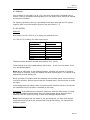
Nautor's
SWAN 48 S C/R
Owner’s Manual
Nautor’s
SWAN 48 S CRUISER/RACER
VERSION
Page 1
Nautor's
SWAN 48 S C/R
[THIS PAGE INTENSIONALY LEFT BLANK]
Page 2
Nautor's
SWAN 48 S C/R
August 1996
Owner’s Manual
Nautor’s
SWAN 48S CRUISER/RACER VERSION
This manual is intended to give some general maintenance hints and to serve as a
guide to the proper use of equipment.
INDEX
1. HULL
2. DECK
3. INTERIOR
4. ENGINE
5. PLUMBING
6. ELECTRICAL SYSTEMS
7. INSTRUMENTATION AND ELECTRONICS
8. RIG
9. HAULING
10. SPARE PARTS
11. DRAWINGS
12. TOOLS
13. APPENDICES
Page 3
Nautor's
SWAN 48 S C/R
[THIS PAGE INTENSIONALY LEFT BLANK]
Page 4
Nautor's
SWAN 48 S C/R
Section 1:
HULL
Page 5
Nautor's
SWAN 48 S C/R
[THIS PAGE INTENSIONALY LEFT BLANK]
Page 6
Nautor's
SWAN 48 S C/R
1 HULL INDEX
1.1 HULL
1.2 CLEANING
1.3 WAXING
1.4 SCRATCHES
1.5 PATCHING
1.6 UNDERWATER
1.7 ANTIFOULING
1.8 KEEL
1.9 STEERING SYSTEM
1.10 FLOATATION REFERENCE MARKS
Page 7
Nautor's
SWAN 48 S C/R
[THIS PAGE INTENSIONALY LEFT BLANK]
Page 8
Nautor's
SWAN 48 S C/R
1.1 HULL
The hull is of single skin construction with a hand laid glass/aramid hybrid fiber
reinforced polyester resin laminate. A high proportion of the fibers are unidirectional.
Stiffener flanges are reinforced with unidirectional glass.
Inside surfaces of the hull have been finished in polyester topcoat. Standard color is
Norpol GS 8008 grey.
The topsides are finished in Norpol gelcoat. Standard color is NGN 2000 white, for
boot top and cove stripe NGN 7005 blue.
For possible repairs of the hull only compatible materials should be used.
The gelcoat surfaces are not completely maintenance-free. The surface collects dirt
and will slowly lose its gloss. Regular cleaning and waxing is needed to keep the
surfaces in top condition.
1.2 CLEANING
Soap and water or a detergent will remove most of the dirt. Gasoline or kerosene will
remove oil and tar. If they fail, rubbing compound can be tried.
Harsh abrasive and chemical cleaners are not recommended. Wet and dry
sandpaper, 600 grit, is the strongest remedy, and must be followed by polishing with
rubbing compound to restore the gloss. Be careful not to sand through the gelcoat
surface.
1.3 WAXING
Wax your boat at least once every year. Wax seals and protects the surface,
minimizing the collection of dirt. Use special boat wax, or a silicone-free automotive
type.
Do not wax surfaces painted with polyurethane or epoxy. Wax will build up, collect
dirt and then turn yellow. Painted surfaces need only regular washing with mild liquid
soap.
1.4 SCRATCHES
Shallow scratches are rather harmless, but if they are deep and expose the
glassfibers, the laminate might absorb water by capillary action. This will impair the
strength of the laminate, so instant action is needed.
1.5 PATCHING
Pre-accelerated gelcoat for patching is delivered with the boat. The bigger can
contains gelcoat for the hull, the smaller one is for the boot top. The bottle contains
catalyst. Gelcoat can be stored about one year, or appreciably longer if kept in a cool
place. The amount of catalyst to be added is 1.8%, which will give a working time of
about 25 minutes at an ambient temperature of 20°C (68°F). For measuring
catalyst, a graduated cylinder or disposable syringe is convenient. 1.8 ml per 100 g
Page 9
Nautor's
SWAN 48 S C/R
gelcoat makes the right mixture, which equals about 12 drops per ounce. Before
work can start, the damage area must be completely dry. Remove dirt and loose
gelcoat, and de-wax around the edges with wax solvent. The use of acetone,
chloroform, carbon tetrachloride, or methylenechloride is not recommended as they
have a detrimental effect on the laminate if applied too liberally. Rub up the surface
by sanding and put masking tape around the edges to limit the patch. Add catalyst
to a suitable amount of gelcoat and spread the mixture over the damaged area,
filling up a little overthickness, as the material shrinks when curing. To get a smooth
surface, the repair work can be covered with cellophane and squeegeed down. After
about twice the working time mentioned above has elapsed, the patch is cured and
can be wet sanded smooth with 600-grit paper, followed by rubbing compound and
wax. If your boat has been exposed to the sun a lengthy time, the patch at first may
differ in color, but will fade in after a couple of months.
1.6 UNDERWATER
To reduce the risk of osmosis or blistering, Nautor has applied two coats of epoxy tar
over double unpigmented gelcoat layers to the GRP surfaces under the water line. It
is extremely important that the surface is kept intact, as otherwise water might
penetrate into the laminate, and possibly cause problems. Harsh grinding of the
antifouling must therefore be avoided. If the epoxy or gelcoat layers have been
damaged, they have to be restored as soon as possible. However, the risk of getting
osmosis or blistering is small, as the bottom is well protected by the layers of epoxy
tar and gelcoat. Six layers of epoxy is recommended where the gelcoat is missing.
Renewal of the epoxy tar layer is recommended every five years.
1.7 ANTIFOULING
Remember that antifouling contains toxic chemicals which can harm eyes and lungs.
Never dry grind old antifouling as that will cause dust to fly around. Wear
appropriate goggles and a respirator even when wet scrubbing or sanding. Never use
paint removers on glassfiber surfaces, except the type specifically formulated for this
substrate. Antifouling containing copper, lead or mercury may accelerate the
deterioration of the propeller shaft zinc anode.
The best way to remove antifouling is high-pressure water spray.
1.8 KEEL
The keel is cast lead bolted to the bottom structure.
Often, on hauling, it will be noticed that along the joint between the hull and the keel
there is a crack in the filler. This is caused by different thermal expansion and
contraction in the materials and should cause no problems. If the crack opens up
when the boat is lifted, the keel bolts should be tightened. Recommended bolt
torque: M24 260 Nm, M30 510 Nm.
1.9. STEERING SYSTEM
Steering system drawing appended
The rudder stock is made of E-glass composite, and supported by two roller
bearings. These bearings should be greased regularly in order to turn easily.
Page 10
Nautor's
SWAN 48 S C/R
The vertical position of the rudder can be adjusted at the upper end of the stock by
adding or removing shims under the axial bearing surface.
Steering cables should be hand tight. The adjusting screws are located at the
quadrant. Check the cables regularly for wear. If there are any broken strands,
change at the earliest opportunity.
The steering wheel shaft has roller bearings which should be kept well greased.
Winch grease or equivalent is recommended.
The emergency tiller is stowed in the lazarette, and should always be kept easily
available. Practice its installation, which could save vital time should it ever be
required.
1.10 FLOATATION REFERENCE MARKS
At bow and stern there are reference marks twelve inches (305 mm) above datum
water line. With the aid of these the exact floatation can be determined.
Note: Floatation is normally heavier than DWL - this is provided as a reference only.
Page 11
Nautor's
SWAN 48 S C/R
[THIS PAGE INTENSIONALY LEFT BLANK]
Page 12
Nautor's
SWAN 48 S C/R
Section 2:
DECK
Page 13
Nautor's
SWAN 48 S C/R
[THIS PAGE INTENSIONALY LEFT BLANK]
Page 14
Nautor's
SWAN 48 S C/R
2. DECK INDEX
2.1 DECK
2.2 LIFERAFT STOWAGE
2.3 WINCHES
2.4 BLOCKS AND SHEET CARS
2.5 WINDOWS AND HATCHES
2.6 ANCHOR WINDLASS
2.7 TEAKDECK
Page 15
Nautor's
SWAN 48 S C/R
[THIS PAGE INTENSIONALY LEFT BLANK]
Page 16
Nautor's
SWAN 48 S C/R
2.1 DECK
Deck arrangement appended.
The deck is a PVC foam cored sandwich construction using the same materials as the
hull, with hard core areas under fittings.
The deck is finished in Norpol gelcoat. Standard color is NGN 2000 white, for the
coaming stripe NGN 7005 blue.
Maintenance directions for the deck are the same as for the hull, see Section 1.
2.2 LIFERAFT STOWAGE
Check occasionally that the rafts are dry, as they otherwise may suffer.
Do not stow other equipment so it prevents access to the rafts.
2.3 WINCHES
Directions for use and servicing are given in Lewmar's System Service Manual. The
winches and deck hardware are fastened through deck to aluminum back-up plates.
After offshore trips rinse the winches with fresh water to remove salt deposits and
reduce corrosion. Winches should be kept well lubricated. Check regularly that winch
base drain holes are open.
2.4 BLOCKS AND SHEET CARS
Maintenance instructions for Harken hardware is appended.
Halyard arrangement
The layout of the halyard exits on the mast requires that the halyards and lifts are
arranged as shown on the deck arrangement drawing.
2.5 WINDOWS AND HATCHES
The side windows and deck hatches are made of tinted acrylic. Wash the windows
with mild liquid soap. Do not use solvents or abrasives.
Page 17
Nautor's
SWAN 48 S C/R
[THIS PAGE INTENSIONALY LEFT BLANK]
Page 18
Nautor's
SWAN 48 S C/R
Section 3:
INTERIOR
Page 19
Nautor's
SWAN 48 S C/R
[THIS PAGE INTENSIONALY LEFT BLANK]
Page 20
Nautor's
SWAN 48 S C/R
3. INTERIOR INDEX
3.1 GENERAL
3.2 FLOORBOARDS
3.3 OVERHEAD PANELS
Page 21
Nautor's
SWAN 48 S C/R
[THIS PAGE INTENSIONALY LEFT BLANK]
Page 22
Nautor's
SWAN 48 S C/R
3.1 GENERAL
Interior arrangement appended.
Take care of the interior, keep the boat well ventilated at all times. All wood surfaces
are varnished with several coats of SADOLUX varnish.
If any damage should occur, sand smooth with light sandpaper and apply SADOLUX
varnish or equivalent. To restore the satin finish the varnish needs to be polished.
After long ocean passages, wash away the salt from the varnished surfaces with
lukewarm water, and spray all metal hinges with corrosion preservative.
Once a year the interior should be wiped with teak oil.
3.2 FLOORBOARDS
Floorboards are made of water-proof plywood covered with teak veneers.
The floorboards are varnished with several coats of INTERNATIONAL CABIN varnish.
If a floorboard should stick, plane the edge with a 10° under bevel to restore easy
fit.
3.3 OVERHEAD PANELS
The overhead panels are finished in FINLAYSON vinyl. The panels are held up by
Velcro strips and can be released by pulling down from one corner.
CAUTION:
The halogen lights used in the overhead have a reflector behind the bulb. This
concentrates the light energy, and items brought close to the light will heat up and
possibly catch fire.
Take care to keep flammable materials and also locker doors away from the lights.
Page 23
Nautor's
SWAN 48 S C/R
[THIS PAGE INTENSIONALY LEFT BLANK]
Page 24
Nautor's
SWAN 48 S C/R
Section 4:
PROPULSION
Page 25
Nautor's
SWAN 48 S C/R
[THIS PAGE INTENSIONALY LEFT BLANK]
Page 26
Nautor's
SWAN 48 S C/R
4. ENGINE INDEX
4.1 MAIN ENGINE
4.2 PROPELLER SHAFT ARRANGEMENT
4.3 FUEL SYSTEM
4.4 EXHAUST SYSTEM
4.5 COOLING SYSTEM
4.6 LUB. OIL SYSTEM
4.7 MAX-PROP FEATHERING PROPELLER
4.8 RECOMMENDATIONS
Engine installation drawing 3-41-0206.
Page 27
Nautor's
SWAN 48 S C/R
[THIS PAGE INTENSIONALY LEFT BLANK]
Page 28
Nautor's
SWAN 48 S C/R
4.1 MAIN ENGINE
The engine is a Volvo MD22 4-cylinder marine diesel with MS2A reverse/reduction
gear 3.0:1.
The engine is equipped with front end power take off for an additional alternator and
refrigeration compressor. Under the engine is a drip tray. Engine oil can be drained
with a separate drain pump.
4.2 PROPELLER SHAFT ARRANGEMENT
Drawing No. 3-41-0206.
Max-Prop Manual
Shaft Seal Manual
The propeller shaft is made of 0 35 mm high tensile corrosion resistant steel with a
flexible shaft coupling at the front end. The shaft is supported by one rubber bearing
in the bracket.
The propeller is a three-blade feathering Max-Prop with 580 mm diameter. For
information about the use of the Max-Prop, please see Section 4.7.
A "PSS" maintenance-free propeller shaft seal is fitted at the stern tube
If the seal leaks, the compression in the bellows should be checked, see the PSS
Manual.
One zinc anode is clamped to the propeller shaft. If the zinc is eaten away quickly,
this indicates a problem in the electrical system. A test diagram is available from
Nautor on request.
4.3 FUEL SYSTEM
Drawing No. 3-51-0816.
One stainless tank is installed with a total capacity of 300 L. The tank is fitted with
access cover and sounding plug. One deck filler cap SB side.
The approximate fuel level in the tank can be checked with the gauges provided on
the engine control panel in the aft cockpit.
Shut off valves for the tank are located in front of the engine room. Tank
is vented to deck edge.
One "Separ" fuel filter/water separator with 10 Micron filter element, alarm and glass
bowl is installed in the feed line.
An alarm for high water level in the separator is located on the main switchboard,
and if it lights up, the separator should be drained at the earliest opportunity. A drain
screw is provided under the separator. Keep a small cup ready when opening the
drain.
Page 29
Nautor's
SWAN 48 S C/R
The fuel system may need to be aired after draining the separator, but usually it is
sufficient just to increase fuel system pressure with the engine fuel pump, which also
can be worked by hand. Pump until a resistance is felt.
CAUTION:
Water in the fuel will cause severe damage if it reaches the engine fuel injection
pump.
4.4 EXHAUST SYSTEM
Drawing No. 3-41-0206.
Wet exhaust system with SS silencer provided with a drain tap. Discharge at
transom.
If starting problems are experienced, the raw water pump will convey water into the
exhaust system, which may fill up after prolonged attempts. If the engine does not
start, the silencer drain tap has to be opened to let the water out. Also when sailing
in storm conditions it is advisable to keep the drain open.
Note: The exhaust system must not be run dry, as the rubber parts very soon will be
destroyed, and could even catch fire with disastrous results.
4.5 COOLING SYSTEM
See Plumbing drawing included.
The engine has thermostat controlled freshwater cooling with heat exchanger and its
own seawater intake and strainer. An anti-siphon loop for the engine is located in the
engine compartment, and the bleed line is led to the cockpit drain. A small part of
the engine cooling water is also led to the propeller shaft seal, which has a
connection for this.
4.6 LUB. OIL SYSTEM
Engine
Gearbox
oil sump capacity approx. 6L (max.)
oil sump capacity approx. 0.8L (max.)
4.7 MAX-PROP FEATHERING PROPELLER
The feathering propeller will give good service as long as it is used with reasonable
care. The following points should be kept in mind.
1. Avoid shifting between "forward" and "reverse" at more than idle engine
speed. Excessively rapid gear shift can damage the propeller mechanism.
2. The propeller needs some time to reverse the blades, and will not respond
instantly to a gear shift. Shift at idling rpms, and check that the propeller
drives in the correct direction before increasing engine rpms.
3. A too rapid gear shift immediately followed by full power may prevent the
blades from reversing properly, and cause the propeller to drive in the
Page 30
Nautor's
SWAN 48 S C/R
OPPOSITE direction, i.e. the same as before the gear shift. The consequences
may be catastrophic.
4. The blades can feather to sailing position only from the forward position, and
not from reverse. Whenever the boat is out of the water, make sure that the
blade mechanism moves freely. Otherwise the water stream will not be able
to turn the blades to the desired fore and aft sailing position.
5. To make the propeller feather it is recommended that the engine be stopped
with the gear in forward.
6. If the propeller persists in turning after the engine has been stopped, it is
necessary to start up the engine again, and put the gear in reverse for a very
brief moment until the shaft stops. Do not allow the propeller to go into
reverse (see point 4 above), which would be indicated by the shaft turning
the other way.
4.8 RECOMMENDATIONS
Do not start up the engine with the propeller in gear. The sudden thrust may cause
crew members to lose their balance. The engine is also more difficult to start with
the gear engaged.
To put the gear in neutral for starting up, pull out the gear shift lever before
advancing the throttle to starting position.
Do not run the engine at heeling angles over 15 degrees neither for propulsion nor
for charging.
Do not run the engine at full throttle for extended periods except in an emergency.
For normal use, slow down to 200 rpm below the maximum attainable engine speed,
or less than that if a low fuel consumption is desirable. See the Speed-ConsumptionRange-diagram 4-44-0463 for more information on this subject.
Do not use engine rpms below 1500 for sustained cruising. Because there is very
little load the engine collects a lot of soot deposits. It helps to rev up the engine
occasionally to maximum power, but do not do this in harbor, as a black cloud of
soot is likely to emerge from the exhaust.
Page 31
Nautor's
SWAN 48 S C/R
[THIS PAGE INTENSIONALY LEFT BLANK]
Page 32
Nautor's
SWAN 48 S C/R
Section 5:
PLUMBING
Page 33
Nautor's
SWAN 48 S C/R
[THIS PAGE INTENSIONALY LEFT BLANK]
Page 34
Nautor's
SWAN 48 S C/R
5. PLUMBING INDEX
5.1 FRESH WATER SYSTEM
5.2 SEA WATER SYSTEM
5.3 DRAINAGE SYSTEM
5.4 TOILET SYSTEM
5.5 BILGE PUMP SYSTEM
5.6 REFRIGERATION SYSTEM
5.7 VENTILATION
5.8 WATERMAKER
5.9 LPG SYSTEM
Installations drawing No. 2-51-0812.
Page 35
Nautor's
SWAN 48 S C/R
[THIS PAGE INTENSIONALY LEFT BLANK]
Page 36
Nautor's
SWAN 48 S C/R
5.1 FRESH WATER SYSTEM
Plumbing drawing No. 3-51 -0816
In warmer climates care must be taken that the water carried in the tanks is potable.
Carry your own water hose, or flush the shore supply thoroughly before filling. Do
not fill the tanks more than necessary. At the end of a cruise, or before refilling,
drain the tanks completely.
Water capacity is 430 1 in two tanks with one filler line from deck terminating at the
fresh water valve chest.
The chest has a valve for each tank. These valves must be open when taking water.
When water flows out through a tank vent pipe into the galley sink this indicates that
the tank is full and its valve can be closed.
Note: In normal use only one tank valve at a time should be kept open, otherwise
water may flow to the leeward tank when the boat heels, and cause overflow into the
sinks.
Pressure water
Pressurized water is supplied by a pump assisted by a pressure accumulator. Inside
the pressure vessel is an air volume, which should have a pressure of 1 bar with no
pressure in the water system. The system is controlled by a switch marked WATER
PRESS on the main switchboard.
Hot water
One 22L hot water tank is installed in the aft cabin. The tank is equipped with a
heat-exchanger connected to the main engine cooling water circuit, and also has a
heating element working on AC.
These heat the water in the tank to 85°C (185°F).
The temperature of the hot water coming from the faucets is reduced to 55°C
(130°F) by a thermostatic mixing valve connected between the hot water tank's inand outgoing lines. The mixing valve allows temperature adjustment between 38 and
65°C (1 00 and 150°F).
Our attention has been drawn to a small error in the text part of the Owner's Manual.
In the section about the seacocks, the words "open" and "closed" have mistakenly
changed places. This has now been corrected, and we kindly ask you to replace the
incorrect page in your manual with the corrected page, which is enclosed.
5.2 SEA WATER SYSTEM
Plumbing drawing included. Through-hull fittings location drawing No. 2-53-0363.
Sea water is used for the refrigeration unit, (optional watermaker) and toilet
flushing.
Seacocks
Bronze seacocks are installed on all through-hull openings below waterline. See
manufacturer's leaflet.
Page 37
Nautor's
SWAN 48 S C/R
The seacock is closed when the handle is touching the hose from either side, and
open with the handle pointing away from the hose.
It should be noted that insurance does not cover damage caused by leaks, if the
water entered through an open seacock. A burst sea water hose could, as an
example, cause this sort of damage.
It is therefore advisable to always close the seacocks when leaving the boat
unattended. An additional benefit is that there is less tendency for the seacocks to
"freeze up" if they are moved regularly.
5.3 DRAINAGE SYSTEM
Plumbing drawing included.
Galley sinks drain through seacock. Aft wash basin and shower drain to sump tank
with a capacity of 60 L. This sump tank can be emptied overboard by an electric
pump with manual back-up. Forward shower pan is drained with an electric pump
discharging through outlet above waterline. Forward washbasin is drained to
seacock.
5.4 TOILET SYSTEM
Plumbing drawing included.
Seawater is used for flushing. The toilets discharge directly overboard, or into a
holding tank (aft head).
5.5 BILGE PUMP SYSTEM
See Plumbing drawing
There are two manual 85 L/min Whale Gusher 10 pumps for pumping out the bilge,
one located in the cockpit and the other under the saloon floorboards.
There is one electric submersible pump with automatic or manual control.
5.6 REFRIGERATION SYSTEM
Drawing included.
The compressor unit is engine driven. There are hold-over plates in the fridge and
freezer.
The condensor is cooled by seawater bypassed from the engine seawater cooling
line.
It is recommended to run the system 1.5 to 2 hours per day, preferably in two
spells.
Note: Do not run the engine driven refrigeration system while maneuvering in
harbor. The system works best when constant engine rpms are used.
Page 38
Nautor's
SWAN 48 S C/R
The temperature in the refrigerator is controlled by its own thermostat. The
thermostat display shows the surface temperature of the hold-over plate. The
temperature should be set to -5°C and the difference to 4°C.
The freezer temperature is also controlled by its own thermostat. In order to use the
hold-over capacity, i.e. keeping the same temperature for hours without running the
compressor, it is necessary to set the freezer thermostat to -25°C and the difference
to 5°C.
Note: The freezer can also be used as a fridge simply by setting its thermostat to for
example -3"C, but then the hold-over system does not work.
The temperatures in the boxes are displayed in the galley on digital thermometers,
which also show the thermostat setting when the set button is pushed. The
thermostat settings can be adjusted as follows:
I. Temperature
a. Press set button
b. Step up or down by pushing the arrow buttons
c. Confirm the chosen temperature by pressing the enter button
II. Difference
a. Press enter button
b. Step up or down by pushing the arrow buttons
c. Confirm the chosen difference by pressing the enter button.
For defrosting there is a small switch near each thermometer which can be used to
shut off the refrigeration for either box independently.
5.7 VENTILATION
The cabins have natural ventilation.
Engine space air inlet in cockpit, outlet with blower to transom. Battery box
ventilated to mast.
5.8 WATERMAKER (OPTIONAL)
Do not run the watermaker in harbor unless the water is perfectly clean. Oil and dirt
will otherwise clog the filters.
5.9 LPG SYSTEM
Drawing No. 4-55-0138.
Space for two 6 kg aluminum Caravan gas bottles is provided in a drained locker in
the stern. Pressure regulator (30 mbar), manual leak detector and remote magnetic
shut off valve are placed inside the locker.
Note that the magnetic shut off valve working temperature will be between 60 and
80°C (140 and 176°F) if kept open for long periods. It is advisable to keep this valve
closed when not cooking.
In the galley there is also a manual gas shut off valve.
Page 39
Nautor's
SWAN 48 S C/R
It is recommended to extinguish the cooker flame by shutting off the remotely
controlled valve, thereby leaving no gas in the pipe run. Check the gas line for
tightness every month, and after rough passages. An easy method is to apply soap
water with a brush over the suspected areas.
To extend the life span of the flexible LPG hose to the stove it is recommended that
the stove be locked with the hook provided when not cooking.
WARNING!
Never check the gas line with an open flame!
Never leave a lighted stove unattended!
Page 40
Nautor's
SWAN 48 S C/R
Section 6:
ELECTRICAL SYSTEMS
Page 41
Nautor's
SWAN 48 S C/R
[THIS PAGE INTENSIONALY LEFT BLANK]
Page 42
Nautor's
SWAN 48 S C/R
6. ELECTRIC SYSTEM INDEX
6.1 GENERAL
6.2 DC SYSTEM
6.3 AC SYSTEM
6.4 POWER SOURCES
6.5 DC ELECTRIC CONSUMERS
6.6 PANELS AND CONTROLS
6.7 LIGHTING
6.8 ALARM AND METERING SYSTEM
LIST OF DFWWINGS
Page 43
Nautor's
SWAN 48 S C/R
[THIS PAGE INTENSIONALY LEFT BLANK]
Page 44
Nautor's
SWAN 48 S C/R
6.1 GENERAL
Service power is provided by a 24 V DC, two-wire ungrounded (insulated return)
system. There is a separate starting battery for the engine which cannot be drained
by the service system.
For lightning protection the rig is grounded to the keel. Note that the DC-system
negative pole is not connected to ground. See also Section 7.5.
6.2 DC-SYSTEM
Batteries
One battery set 24 V 320 Ah (5 h rating) for general service.
12 V 90 Ah (20 h rating) for main engine start.
Open circuit
battery voltage
25.4V
25.2V
25.0V
24.8V
24.4V
24.2V
24.0V
Battery status
100% charge
85%
70%
55%
40%
25%
10%
The above table assumes ambient temperature 20°C (68°F).
The acid level for a fully loaded battery should be 3 - 8 mm over the plates. If too
low, add distilled water.
Note: Never add water to a discharged battery, because the process of charging
may cause an overflow, which will weaken the acid concentration. This results in an
appreciably shorter battery life.
Never use open fire nearby when the batteries are checked. Never move acid from
one cell to another. Before the cell caps are screwed down, check that the air holes
are open.
Check and grease the battery cable connections with Vaseline monthly. Check that
the ventilation hose is properly connected to the mast.
Important! If the batteries are removed, make sure that the main switch is turned
off, and the cables marked before they are disconnected. Never disconnect the
batteries with the engine running, as that could damage the alternator.
Note: Electrical parts and salt water do not get along well, so make sure that all
vulnerable electrical parts are sprayed often with preservatives, for example CRC
SP400 or similar.
Battery charging
Page 45
Nautor's
SWAN 48 S C/R
Battery voltage should be checked regularly. If the open-circuit voltage in either
battery is below 24.4 respective 12.2 volts, charging is necessary. One to four hours
charging per day is recommended, depending on usage. An engine alternator
charges the service batteries and another engine alternator charges the engine
starting battery. At engine revolutions over 1000 rpm the Ammeter should display
positive charging. Recommended charging rpm is 1800. The Ammeter displays only
service battery charging.
The charging current reaches its maximum immediately after starting, and then
gradually decreases as the batteries become charged. If the Ammeter does not
display any charging after starting, the V-belt drive for the alternators should be
checked for correct tension. The tension should be checked after the first 5 hours of
engine running, and after that every 50 hours.
There is also a 50 A battery charger with automatic regulation, working on AC.
Take care to charge the batteries before leaving the boat.
Battery output
By definition, battery capacity is the output during a number of hours of constant
discharging. Two ratings are generally used, the 20 hour and the 5 hour rating.
The service batteries can produce 385/20 = 19 Amperes during 20 hours, or
320/5 = 64 Amperes during 5 hours, depending on which rating is chosen.
It should be noted that because of increasing internal losses associated with higher
Amperage output, the 5 hour output is reduced to 83% of the 20 hour output.
Batterv location
The batteries are located in the sofa port side of mast in the saloon and ventilated to
the mast.
Main switch
There is one DC main switch common for main engine and service batteries.
The switch is located in the saloon table base with access from the starboard side.
Main fuse
The DC main fuse is located with the main switch.
CAUTION:
Do not switch off the main switch during charging or under heavy loads as this could
damage the charging equipment.
6.3 AC-SYSTEM
Page 46
Nautor's
SWAN 48 S C/R
Note: When the AC-system is used, the DC-system has to be activated, i.e. the main
service switch has to be in ON-position as some AC-system control circuits also need
DC-supply.
Shore supplv
Shore supply inlet socket for 230 V is located on the coaming on aft deck. The
automatic fuse for the shore inlet is located on the AC panel at the chart table.
Important! Make sure that the shore voltage matches with the boat installation.
WARNING:
To minimize shock and fire hazards:
• Turn off the boat's shore connection switch before connecting or
disconnecting shore cable.
• Connect shore power cable at the boat first.
• If the polarity alarm - a red light on the AC switchboard - lights up when the
land end of the cable is connected, immediately disconnect cable and have
the fault corrected by a qualified electrician. Wrong polarity in % the ACsystem may be lethal.
• Disconnect shore power cable at shore outlet first.
• Do not allow the cable to hang in the water.
AC consumers
• AC outlets
• Battery charger
• Hot water tank
• 230 V refrigeration
• Stove electric grill
Make sure that the shore frequency matches with the AC appliances you intend to
use. When nothing is mentioned, the appliances accept both 50 and 60 Hz.
Each 230V consumer has its own automatic fuse and the outlet groups have an earth
fault protection breaker.
Note: Before switching on any AC consumer, check that the voltage displayed on the
switchboard is within acceptable limits, i.e. between 200 and 240V. Before switching
on the hot water tank element, open a hot water faucet to ensure the tank is filled
with water.
6.4 POWER SOURCES
6.4.1 AC POWER SOURCES
Shore power 230V 25A 50Hz 1 phase.
6.4.2 DC POWER SOURCES
- BATTERYCHARGER
One 50 A battery charger is provided for the service battery bank.
Page 47
Nautor's
SWAN 48 S C/R
Check that the DC main switch is ON before the AC switch marked SERVICE
BATTERY CHARGER is turned on. The Ammeter should then display positive charging.
Note: If there is a heavy DC load the Ammeter might show discharging, because it
indicates the difference between charging and discharging current. Only with all
consumers switched off does the Ammeter display the actual output from the
charger.
For further information about the charger, see manufacturer's manuals.
- ALTERNATORS ON MAIN ENGINE
Alternator 1, 60 A 24 V DC, for service batteries.
Alternator 2, 60 A 12 V DC, for main engine starting batteries.
6.5 DC ELECTRIC CONSUMERS
6.5.1 LIGHTS
The boat is divided into a number of lighting circuits, controlled via automatic fuses
on the main panel.
Each compartment has its own lighting switch or switches. Red lights, one in the nav.
station and one in the saloon, are controlled from the main panel.
6.5.2 PUMPS
- PRESSURE WATER PUMP
The pump is provided with automatic fuse on the main panel with control and
warning light.
- AUTOMATIC BILGE PUMP
One Volvo QL SBP 7500 pump with control switch and warning light on the main
panel. The fuse is in the main switch box. The pump has automatic and manual
function. The automatic function is activated by a bilge level sender.
- SUMP PUMPS
Whale Gulper pumps. Aft toilet sump pump is started with a push button and
stopped by a vacuum switch when tank is empty. Forward toilet sump pump is
operated by an on/off push button.
6.5.3 FANS
Toilet fans:
There is a separate fan controlled by a push button in each toilet.
Engine room fan:
Page 48
Nautor's
SWAN 48 S C/R
- 1 x GNG 4.5 m3/min.
The fan is controlled by a thermostat which senses the engine room temperature
with cut in at 60°C. The fuse is located in the Relay box.
Gallev fan:
- 1 x GNG
The fan is controlled by a switch on the refr. panel in the galley. The automatic fuse
is on the main panel.
6.5.4 WINCHES
Emergency stop on starboard side of steering pedestal for anchor windlass and
electric winches.
6.6 PANELS AND CONTROLS
6.6.1 DC MAlN PANEL
Located at the chart table.
6.6.2 COCKPIT PANEL
Aft cockpit panel on SB side is for engine controls.
6.6.3 AC MAlN PANEL
The main AC panel is located at the chart table and is equipped with main switch,
polarity alarm, automatic fuses and volt/ampere meters.
6.6.4 DC CONTROL BOX
Relay box located in locker in aft toilet. Of plastic sealed type.
6.7 LIGHTING
- INTERIOR LIGHTS, see 6.4.1.
- DECK LIGHTS
There is a floodlight down on the mast.
- NAV. LIGHTS
The nav. light switches are located on the main DC panel which includes a
supervision light for them.
- MAST WIRING
Is led to a multi-pin connecting plug at the mast step.
6.8. ALARM AND METERING SYSTEMS
Page 49
Nautor's
SWAN 48 S C/R
6.8.1 HOLDING TANK FULL ALARM
This system indicates on the main panel when the holding tank level is high or full.
6.8.2 WATER METERING SYSTEM
Each water tank has a water tank level sender which is connected to a gauge via a
selector. The selector activates the system. The gauge and the selector are located
on the refr. panel in the galley.
6.8.3 FUEL METERING SYSTEM
The fuel tank has a level sender connected to a gauge in the aft cockpit.
The system is activated when the engine control is in ON-position.
The water in fuel separator filter has indication on the main DC panel for high water
level.
ELECTRICAL DRAWINGS
Drawing no
3-61-0528
4-63-0102
4-64-0604
4-64-0669
4-64-0874
4-64-0875
4-64-0877
4-64-0879
4-64-0880
4-64-0897
4-64-0898
3-64-0961
1-64-0967
4-65-0290A
4-65-0397
4-65-0432
4-65-0542
4-65-0548
4-65-0552
4-65-0568
4-65-0580
3-65-0622
4-65-0629
3-66-0263
3-68-0049
4-68-0051
4-68-0052
4-69-0136
Descpition
AC-diagram & Inv. Heart 1500W
Windlass Lewmar Concept
Outlets watertight
Mast connection 24-pole
Lights Aft
Lights Mid
Lights Fwd 2 cab
Deck Lights
Panel meters V+A+Ah
Outlets 12V (24V)
Night Lights & Leading light
DC-System & Inv. 1500W & Watermaker
Lights & Switches
Water in fuel alarm
Deck wash pump
Gas shut-off wiring
Water pressure pump
Holding tank alarm
Water tank gauge
Sump pump in fwd toilet
Bilge pump: OL SBP 7500 & level switch
Refr./freezer system engine & 115V AC driven
Sump pump with time relay
Engine wiring diagram
Heater diagram D5W
Engine room ventilation
Ventilation pentry + turbofans
Dimmer Cantalupi
Page 50
Nautor's
SWAN 48 S C/R
Section 7:
INSTRUMENTS
Page 51
Nautor's
SWAN 48 S C/R
[THIS PAGE INTENSIONALY LEFT BLANK]
Page 52
Nautor's
SWAN 48 S C/R
7. NAVIGATIONAL EQUIPMENT INDEX
7.1 GENERAL
7.2 AUTOHELM
7.3 MISCELLANEOUS
7.4 ANTENNAS
7.5 ADDING ELECTRONICS LATER
Navigation area drawing 2-33-1799.
Page 53
Nautor's
SWAN 48 S C/R
[THIS PAGE INTENSIONALY LEFT BLANK]
Page 54
Nautor's
SWAN 48 S C/R
7.1 GENERAL
Only a few hints will be given here, the actual instructions for use, maintenance etc.
are being explained in detail in the corresponding manuals.
7.2 AUTOHELM
The speed transducer is mounted on CL in the forward part of the guest cabins under
the floorboards.
The depth transducer is mounted on CL in the aft part of the guest cabins under the
floorboards.
The autopilot compass is mounted in the aft cabin together with the course
computer.
7.3 MISCELLANEOUS
The tuner unit for the SSB (if fitted) is in the lazarette, close to the backstay.
All 24Vl12V converters are mounted behind the panels in the chart table area.
7.4 ANTENNAS
The only antenna in the mast is the VHF antenna. The GPS antenna is mounted on
the deck near the transom.
The insulated backstay is used as SSB antenna through an automatic antenna tuning
unit mounted in the lazarette.
As ground for the coupler a "grounding cage" is glassed in, covering the major part
of the lazarette.
All antenna plugs, especially those above deck, should be checked regularly and if
needed be cleaned and treated with moisture repellent anti-corrosion spray.
7.5 ADDING ELECTRONICS LATER
The DC electrical system on Swans is of the two-pole insulated return type. This
means that negative and ground are separated.
If electronics are added to the boat at a later date, care must be taken that these do
not upset the original electrical system. The result may be severe corrosion to
underwater parts.
It has therefore to be checked before installation whether new devices meet the
insulation requirement. In case negative and ground are not separated, installation
advice should be sought from Nautor, mentioning the type and I model of the new
piece of equipment.
Page 55
Nautor's
SWAN 48 S C/R
[THIS PAGE INTENSIONALY LEFT BLANK]
Page 56
Nautor's
SWAN 48 S C/R
Section 8:
RIG
Page 57
Nautor's
SWAN 48 S C/R
[THIS PAGE INTENSIONALY LEFT BLANK]
Page 58
Nautor's
SWAN 48 S C/R
8. RIG INDEX
8.1 SPARS
8.2 STEPPING THE MAST
8.3 MAST WEDGING
8.4 TIE RODS
8.5 STANDING RIGGING
8.6 MAST BEND
8.7 RUNNERS AND INNER FORESTAY
8.8 SPINNAKER AFT GUY
8.9 NAVTEC SYSTEM V HYDRAULICS
8.10 SETTING UP THE RIG
8.11 WORKING LOAD IN THE BACKSTAY
8.12 LAZY JACKS
8.13 LUFF CARS
8.14 HARKEN FURLER
Sail plan appended.
Page 59
Nautor's
SWAN 48 S C/R
[THIS PAGE INTENSIONALY LEFT BLANK]
Page 60
Nautor's
SWAN 48 S C/R
8.1 SPARS
The mast and boom are tapered and welded aluminium extrusions. Poles are tubular
aluminum. The spars are anodized.
Hose down the spars and pole fittings with fresh water after each journey. Do not
forget the inside of the mast and its step, which can be rinsed through the halyard
exits. If the spars get scratched, clean the scratches and cover them with metal
lacquer or wax.
8.2 STEPPING OF THE MAST
The weight of the mast, including rigging, is about 400 kgs. When inserting the mast
heel through the deck opening, be careful not to damage the cables and hoses
emerging from the mast when it goes into the step. Connection points for mast
cables are found near the mast step.
8.3 MAST WEDGING
Drawing appended
The mast must be held securely at the deck, and this is achieved with the rubber
wedges supplied. The first wedge is easy to slip into position, but for the second a
strong tackle is needed. The end result should be that the wedges are under
considerable pressure. Then the rubber boot should be tightened around the mast to
stop leakage, and protected from the sun with the canvas collar.
8.4 TIE RODS
The main bulkhead incorporates vertical tie rods each side of the mast to resist the
halyard loads. The tie rods should be tight but not tensioned with the halyards slack.
8.5 STANDING RIGGING
Navtec rod rigging is used for the standing rigging. Solid rod has less elastic stretch
than wire, and can accept higher transient loadings. Consequently tuning is more
permanent. When the mast is unstepped, the rods should be handled very carefully,
bends, scratches and kinks must be avoided by all means. At each spreader tip there
is a fitting which positively locks the spreader tip in position on the rod.
Note: Do not use cleaners containing ammonium on bronze rigging parts, as this
could cause cracking of the material.
8.6 MASTBEND
Mast bend should be limited to about one or two mast diameters. A mast bent out of
column cannot support the masthead properly. The result is that not enough tension
can be developed in the headstay to reduce genoa luff sag to an acceptable level.
The 15/16 rig needs to be set up with prebend to prevent it from inverting.
Page 61
Nautor's
SWAN 48 S C/R
8.7 RUNNERS, INNER FORESTAY AND BABYSTAY
15/16 riq:
The runners are needed to achieve proper headstay tension in stronger winds, in
light conditions the backstay is able to do this alone. A flying babystay set up to
oppose the spinnaker pole pressure is recommended in strong winds.
Masthead riq:
The runners are supplied as preventers to stabilize the mast, and also to tension the
inner forestay when carrying a staysail. Do not over tension the runners when they
are used as preventers only. This is particularly important for the checkstays.
Except in light flat water conditions the babystay is always necessary. In choppy
conditions and when shy reaching with a spinnaker it is particularly important to
have it properly set up.
8.8 SPINNAKER AFT GUY
An aft guy taken straight to the foot block will bend the lifeline stanchions. The aft
guy should therefore be led through a block attached to the side deck amidships and
then preferably taken directly 'to the primary winch.
8.9 NAVTEC SYSTEM V HYDRAULICS
The size of the hydraulic cylinders is adapted to the strength of the attached stays.
The maximum pressure for the different function is limited by an internal relief valve,
factory set to open at 4000 psi.
The relief valve is in effect only for the function selected on the panel.
The hydraulic cylinders are very powerful, and can quite easily overload the rig.
If you are interested to know the actual forces in kN or lbs, consult the hydraulic load
diagram in Section 8.1 1. Cylinder size as follows:
Backstay
Vang
2 x - 8 S (short stroke)
- 12
The hydraulic system is filled at the yard with NESTE PAINE 32 or equal and has an
oil container in the upper pad of the steering pedestal. The level in this container
should be checked periodically. Always use the right oil, i.e. the brand filled at the
yard, or another non-detergent mineral oil SAE 5 or 10.
The boom vang has high pressure gas return, which will force the boom up when the
hydraulic pressure is released.
The other cylinders are provided with a tire valve so the return side can be
pressurized with air to make them extend when the hydraulic pressure is released.
Recommended air pressure is 8.5 kp/cm2 (120 psi) with the cylinder fully extended.
Page 62
Nautor's
SWAN 48 S C/R
Note: With a hydraulic boom vang, the panel selector valve should be set in VANG
position when running in broaching conditions. The relief valve is then in effect if the
boom eventually is submerged. Also, the manual release is ready for immediate use.
Keep the mast fairly straight. A mast bent out of column cannot support the
masthead properly. The result is that no enough tension can be developed in the
headstay to reduce genoa luff sag to an acceptable level.
WARNING:
A heavily loaded vang in combination with excessive mast bend will overload the
mast at deck level.
Do not let crew members unfamiliar with the hydraulics work them. Always keep an
eye on the rig when making adjustments.
8.10 SETTING UP THE RIG
See appendix 2 for a discussion of 15/16 versus masthead rig.
Basically, the shrouds need to be pre-tensioned so much that the leeward ones just
start going slack at the maximum normal sailing angle, with the desired mast bend,
and full working tension in the backstay. There are, however, practical problems
associated with getting the correct tension.
At the dock, it is not possible to achieve that much shroud tension except when the
rigging screws are new, completely clean, well greased, and extension shafts are
used on the spanners. The risk of damaging the threads is inherent; furthermore one
does not know the result until sailing trials are performed.
Another, easier way of getting the correct shroud tension is to go sailing, and tighten
the leeward turnbuckles alternatively on each tack. This can be done fairly quickly if
you observe the following trick: Assuming equal shroud tension initially, on the first
tack count the number of leeward rigging screw turns until the slack is removed.
Then turn the screw back half the number of turns, and jot down this halved
number. On the other tack, turn the recorded number of turns. Now only minor
adjustments should be necessary.
Always half the number of turns you can achieve, and repeat this halved number on
the other side. The end result must be that there are equal numbers of turns each
side. If you leave the rigging screws at the full number of turns on the first tack, the
mast will be pulled so far over to that side that you never get it back into the middle
however much the opposite turnbuckles are tightened.
With discontinuous shrouds, which have turnbuckles at the spreader ends, it is not
very practical to adjust these at sea. There is also a method for setting up the rig at
the dock. This method requires that you are able to heel the boat with the spinnaker
halyard to both sides.
Basically you do the same as described above when sailing, but you need to heel the
boat to only half the sailing angle when heeling to the first side, in this case
tightening the full number of turns. When the boat is heeled to the full angle to the
opposite side, the same number of turns should be applied.
Page 63
Nautor's
SWAN 48 S C/R
8.11 WORKING LOAD IN THE BACKSTAY
Hydraulic load diagram appended.
With Nautor's rig design method, it is possible to determine the necessary backstay
working load in terms of hydraulic pressure. The recommended full working load will
give a fairly straight headstay. To increase the pressure beyond the recommended
limit will have only minor influence on headstay sag, and is not good for the long life
of the rig.
In this connection it is perhaps appropriate to mention that we do not think there is
any expert around who can tell just by looking at a boat what is the correct backstay
pressure to be applied. The pressure is not a measure of the load unless you know
the size of the cylinders. In addition to that you must know the load in relation to the
stability of the boat, and the exact geometry of the rig.
Note: It is recommended that the visible part of the hydraulic cylinder rods be
lubricated monthly in order to prevent salt encrustation. The same recommendation
applies to the boom vang.
8.12 LAZY JACKS
See drawing 4-84-0163 for the rigging of these. Plastic thimbles are used to avoid
chipping of the surface of the mast.
8.13 LUFF CARS
The luff cars for a fully battened mainsail cannot be taken off the mast track unless
they are transferred onto a separate piece of track (otherwise the balls will fall out).
A removable gate in the track is provided about 2 m above the boom.
8.14 HARKEN FURLER
It is recommended that a rope halyard be used with a furling headsail. If the halyard
is wrapped around the top end of the furling section, rope is less likely to cause
damage.
If a headsail with shorter than full hoist is used, a head pennant is required so the
top swivel takes up its normal position near the masthead. If the swivel is too low,
the halyard is likely to wrap itself around the stay.
Page 64
Nautor's
SWAN 48 S C/R
Section 9:
HAULING + STORAGE
Page 65
Nautor's
SWAN 48 S C/R
[THIS PAGE INTENSIONALY LEFT BLANK]
Page 66
Nautor's
SWAN 48 S C/R
9. HAULING INDEX
9.1 HAULING
9.2 STORING ON CRADLE
Page 67
Nautor's
SWAN 48 S C/R
[THIS PAGE INTENSIONALY LEFT BLANK]
Page 68
Nautor's
SWAN 48 S C/R
9.1 HAULING
Docking plan drawing 2-98-0210 appended.
If slings are used, they must have a frame spreading them so they come own to the
deck edge vertically. The slings must be securely fastened so hey cannot slip, and be
carefully positioned not to damage propeller shafting r any protruding fittings. Be
sure that the slings are clean on the inside surface to avoid scratching the hull under
the heavy loading.
9.2 STORING ON A CRADLE
The greatest part of the weight must be taken by the keel. To keep the hull upright,
well padded supporting struts are needed at bulkheads or stringers. There must be a
stopper each end of the keel, preventing the boat from slipping backwards or
forwards.
Page 69
Nautor's
SWAN 48 S C/R
[THIS PAGE INTENSIONALY LEFT BLANK]
Page 70
Nautor's
SWAN 48 S C/R
Section 10:
SPARES
Page 71
Nautor's
SWAN 48 S C/R
[THIS PAGE INTENSIONALY LEFT BLANK]
Page 72
Nautor's
SWAN 48 S C/R
ELECTRIC SPARES
Nautor
Code
Description
2
Part No
Pieces
10
Location
14381
Spade connector female 2,5
160447-2
14382
Spade connector female 62
46047.213.011
10
14383
Spade connector male 2,52
42565-2
10
14384
Spade connector male 62
180409-2
10
15165
Handybox
15257
Bulb 904-00212
24V 18W 12cd BAY15
2
lant
15258
Bulb 904-00213
24V 25W 18cd BAY15
2
lant
15507
Lamp remover
950 KM-R 22/GL
1
15524
Bulb Philips
12913 12V 2W BA9S
2
PMO
15536
Bulb Philips
13864 24V 5W S8.5
5
light rail
windex
1
15538
Bulb Philips
13875 24V 3W E10
2
15539
Bulb Philips
13913 24V 3W BA9S
2
PMO
15541
Bulb Philips Halogen
13091 24V 20W G4
4
ceiling lights
15575
Glassfuse
0,2A slow 5x20m.m
10
PDC
15577
Glassfuse
1,0A 5x20mm
10
PDC, PAC
15580
Glassfuse
5,0A 5x20mm
10
PDC
15680
Relay ESMI
DC 24V nr. 8276
1
BRE
16247
Compass bulb
Suunto 24V
2
compass
16350
Plug 12V Sutar (cig. lighter)
400 3044
1
16370
Plug 230V AC
24040750
3
16599
Olten contact block NO +NO
704 9053
1
PMO
16601
Olten contact block NO +NC
704.9055
1
PMO
16651
Bulb Philips
12516 12V 1,2W RED
2
PMO
16719
Cable tie
SST 2 S 150mm
10
16930
Anchor light 24V 18W 12cd
64-0001
1
anchor light
17640
Olten LED T5,5 Red
24V/20mA 01-968.22
1
gasswitch
17833
Olten neon bulb
115V 01-960.8
2
?AC
17834
Olten neon bulb
230V 01-960.9
2
PAC
18415
Switch Presto
10705/6
1
lightswitch
18416
Switch Presto
10705/5
1
lightswitch
18417
Pushbutton Presto
10510
1
dimmer
18515
Protection spray
CRC SP 400
1
18706
Spade connector housing female
180923-0
5
18707
Spade connector housing male
180924-0
5
18278
Autofuse
5A
10
BBR, BRE
18729
Autofuse
10A
10
BBR, BRE
18730
Autofuse
15A
5
BBR, BRE
18805
Bulb Halogen
Deck light Aqua-Signal 90400308
HMB 50 12V 5W BA9S
1
chart table light
24V 50W Sealed-Beam
1
deck light
18911
19002
Olten contact block NC I-NC
704.9054
1
emerg .stop
19049
Red bulb
24V 5W S8.5 red
4
19504
Autofuse
20A
1
night It
heater glow
plug
19505
Autofuse
25A
1
heater
19667
Autofuse
1A
10
BBR, BRE
20064
Plug DC waterproof Aqua-Signal
83928003 5-pin
2
outlets
20733
Bulb Halogen
24V 10W G4
5
lights
Page 73
Nautor's
SWAN 48 S C/R
LOCATIONS
BFU Box main fuse
BIN Box main inlet fuse
PDC Panel DC
BBR Box main breaker
switch
BAC Box AC
PAC Panel AC
BDG Box main fuse
diesel generator
BRE Box relay
PMO Panel motor
BAR Box AC refr.
PLA Panel lantherns
Page 74
Nautor's
SWAN 48 S C/R
Section 11:
DRAWINGS
Page 75
Nautor's
SWAN 48 S C/R
[THIS PAGE INTENSIONALY LEFT BLANK]
Page 76
Nautor's
SWAN 48 S C/R
Dwg Number
Dwg Title
File Name
1-15-1829B
STYRSYSTEM
FILE0009
1-20-0551
Deck Assembly Masthead Rig
FILE0048
1-30-0537B
Interior Arrangement
FILE0003
1-57-0226A
Ventilation
FILE0015
1-64-0984
Lights and Switches
FILE0031
1-81-2667B
Sailplan Masthead
FILE0049
2-51-0850B
Installations
FILE0005
2-53-0388B
Location of Seacocks and Throught-Hull-Fittings
FILE0004
2-65-0622B
Refr/Freezer System Engine & 115V Driven
FILE0008
2-98-0210
Docking Plan
FILE0053
3-41-0206C
Engine Installation
FILE0011
3-51-0851A
Plumbing
FILE0013
3-51-0960
Plumbing & Istallations Details 1->2 Fuel tanks, 2->3 Water tanks
FILE0001
3-61-0528B
AC-Diagram & Inverter Heart 24V / 1500W
FILE0017
3-64-0879C
Deck Lights
FILE0025
3-64-0961A
DC - System
FILE0030
3-66-0263F
Engine wiring diagram Volvo MD22
FILE0041
3-66-0301B
Engine wiring diagram Volvo MD22
FILE0002
3-68-0049
Eberspcher D5W 24V DC
FILE0042
3-72-0938
Cabling for Instruments
FILE0046
3-82-0903A
Slab Reefing Principle Sketch
FILE0050
4-23-260
Mast Wedging
FILE0010
4-42-0255
Propeller Shaft
FILE0012
4-44-0464A
Speed, Consumption & Range Diagram
FILE0006
4-51-0838
Sounding Table
FILE0007
4-55-0138B
LPG Gas System
FILE0014
4-58-0065
Refr. System Iceberg
FILE0016
4-63-0102C
Anchor Windlass Lewmar
FILE0018
4-64-0604B
Outlet Water tight
FILE0019
4-64-0604B
Outlet Water tight
FILE0027
Page 77
Nautor's
SWAN 48 S C/R
Dwg Number
Dwg Title
File Name
4-64-0669B
Mast Connection 24-Pole
FILE0021
4-64-0874E
Lights AFT
FILE0022
4-64-0875G
Lights MID
FILE0023
4-64-0877A
Lights FWD 2 Cab
FILE0024
4-64-0880B
Panel Meters
FILE0026
4-64-0897A
Outlet 12V (24V)
FILE0028
4-64-0898B
Night Lights and Leading Light
FILE0029
4-65-0290A
Water in fuel alarm
FILE0032
4-65-0397C
Deckwash Pump
FILE0033
4-65-0432C
Gas - Shutoff Wiring
FILE0034
4-65-0542A
Water Pump FLOJET 4325
FILE0035
4-65-0548A
Holding tank alarm FWD and AFT
FILE0036
4-65-0552A
Water metering system
FILE0037
4-65-0568
EL Sump Pump Whale Gulper
FILE0038
4-65-0580
Bilge Pump Johnson L120 QL SBP 7500
FILE0039
4-65-0629
EL Sump Pump Whale Gulper with time relay
FILE0040
4-68-0051A
Engine Room Vent
FILE0043
4-68-0052A
Ventilation Galley Turbo Fans
FILE0044
4-69-0136
Light Dimmer Cantalupi
FILE0045
4-75-0079
Interfacing
FILE0047
4-83-0545
Hydraulic Load Diagram
FILE0051
4-84-0163
Lazy-Jack
FILE0052
Page 78