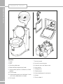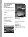
1
fitted equipment Truma heating system and air flow ............................................................................................ 93 Truma digital timer control ....................................................................................................... 93 Truma Combination Boiler fault finding ..................................................................................... 97 Truma Combi 2/4 operating instructions ................................................................................... 97 Truma Combi 2/4 fault finding ................................................................................................. 105 ALDE Compact 3010 ............................................................................................................ 106 ALDE Compact 3010 Control Panel........................................................................................ 110 f itte d e quipme nt Truma Combination Boiler ........................................................................................................ 92 Thetford refrigerators .............................................................................................................. 118 Dometic absorption refrigerators ............................................................................................. 126 Cooker 3 burner and hotplate ................................................................................................. 147 Cooker 3 burner gas hob (Sprite only)..................................................................................... 152 Microwave oven .................................................................................................................... 155 Thetford C260 cassette toilet .................................................................................................. 158 Caravans with external BBQ point .......................................................................................... 165 Caravans with TV inlet in battery box ...................................................................................... 166 Status 530 directional TV and FM radio antenna .................................................................... 167 Bedding .................................................................................................................................. 168 Softrollo Blinds (Seitz) ............................................................................................................. 170 Doorscreen ............................................................................................................................. 170 Roof lights .............................................................................................................................. 170 Exterior Door Key ................................................................................................................... 170 Windows ................................................................................................................................ 171 Heki-2 roof light (Seitz) ............................................................................................................ 171 Mini Heki rooflight ................................................................................................................... 171 Care of laminate tops, tables, furniture and doors ................................................................... 172 Doors ..................................................................................................................................... 172 Tables ..................................................................................................................................... 172 Table storage .......................................................................................................................... 172 12V reading lamp ................................................................................................................... 172 Trigger shower heads.............................................................................................................. 173 Fixing of awnings .................................................................................................................... 173 Paint colour reference.............................................................................................................. 173 Drop down TV mechanism...................................................................................................... 173 Front locker and sunroof.......................................................................................................... 174 Bonded Roof........................................................................................................................... 174 Adjust tension of Horrex blind.................................................................................................. 174 Step on hitch cover................................................................................................................. 174 Cycle racks ............................................................................................................................. 174 Caravan motor mover...............................................................................................................174 Omni-vent............................................................................................................................... 175 91 fit t e d e quip m e n t Truma combi boiler The instructions covering fitted equipment to your caravan were correct at the time of going to print. Owners handbooks are updated annually and we take great care to try and ensure their accuracy. However, the Swift Group Limited cannot accept responsibility for any changes that may be made in specification or operating instructions to the equipment described in this section after the time of going to press. Every care is taken to ensure that the information provided in this handbook is correct and easy to understand. Separate manufacturers’ leaflets on many of the components are also included in the Owner’s Pack provided with this caravan and we recommend that you compare the instructions in the handbook with the component manufacturers literature, to ensure the information provided is as accurate as possible. If you are in any doubt as to how to operate the equipment in your caravan, please contact the component manufacturer’s service department on the telephone number shown on their component leaflet. If you remain in any doubt, please contact your supplying dealer. Truma Combination Boiler The Truma Combination boiler has been designed to run on gas or electric power and the optimum performance is obtained when used in dual fuel mode, that is running on gas and electric at the same time. Running in dual mode has the following benefits: • F astest possible heat up time, the gas burner combines with an electric element to provide energy to heat your hot water and warm your caravan. • T he intelligent heat management system automatically senses when the water and room are nearing the required temperature and then automatically turns off your gas burner and operates solely on electric power, conserving your gas. • A s hot water is used or the room cools the Truma combination heater will continue to operate on electric only until a point where the demands necessitate that additional gas power is required. An example for such a demand could be for instance if the exterior door was left open and the room temperature dropped by 10 degrees in the space of a few minutes, in this case the intelligent heat management system would decide the best way to get the room back to the required temperature would be to use both gas and electric at the same time. Operating the Truma Combination system on electric or gas only will result in longer heat up times for hot water and the room temperature in comparison to operating on dual fuel. Operating on electric only may not in all cases maintain a comfortable room temperature especially in colder conditions. The intelligent heat management system in dual fuel mode allows the Truma Combination boiler to prioritize the electric power source over your gas, this will conserve your gas supply. 92 The Swift Group undertakes considerable testing of our products in cold chambers to ensure they meeting the BS EN 1649 Grade 3 standard and are usable in cold temperatures. During this testing, the air flow on the blown air outlets is defined and set by us. In some cases, customers may wish to alter this setup to achieve a different heating pattern (i.e. more hot air to the rear of the vehicle or vice-versa) and this can be achieved by adjusting the butterfly plate within the blown air outlet. Butterfly outlets Digital Timer Control Challenger and Eccles Sport based models Operating instructions Depending on the specification of your caravan, the CP25 controller may be fitted to control the operation of the Truma Combi appliance. Please be sure to read the instructions for installation and use before attempting to connect and use this device! f itte d e quipme nt Truma Heating System and Air Flow Symbols used ! Symbol indicates a possible hazard. Comment including information and tips. Safety instructions ! To protect you from electrical shocks, injury or burns the following basic safety principles must be observed when using electrical devices. Please read and follow these instructions before using the device. Installation Blown air The air ducting outlets are generally of the butterfly type and may be opened or closed by adjusting the butterfly valves. Twisting the disc in its housing directs the flow in the direction required. One outlet on each leg of the air ducting layout must be kept open at all times. Under no circumstances should the air ducting outlets be blocked. Ensure that the devices are positioned safely and cannot fall down or over. Always position the cables to ensure they do not pose a tripping hazard. Do not expose electrical devices to rain. Do not operate electrical devices in damp or wet environments. Do not operate electrical devices close to flammable liquids or gases. Position the devices so that they are out of the reach of children. Protection against an electrical shock Only operate devices whose casings and cables are undamaged . Ensure the cables are installed safely. Do not pull on the cables. Note: The next instructions detail the operation of the Combi Control Panel - for further details of the Truma Combi appliance, please see the following section. 93 fit t e d e quip m e n t truma digital timer control Use Status of the heater : Do not use electrical devices for purposes other than those stated by the manufacturer. H: Set room temperature (e.g. 18°C) Repairs EG:Energy selection (E = Electro, G = Gas) W: Set water temperature Do not repair or modify the device. Please contact your dealer or the Truma Service (see service manual or www.truma.com). Accessories Only use accessories and additional devices that are supplied or recommended by the manufacturer. Intended use The CP 25-UK is a digital operating / display and control unit for the Combi Boiler. The device is designed to be installed in caravans and motorcaravans. Initial operation or activation after a power cut After the operating voltage has been connected , the unit will beep and the display remains dark. To switch on, press the key 4 and the main screen will appear. Function description Note: More details regarding the operating modes can be found in the operating instructions of your Combi. Main Screen Selection Key upwards to select functions or set values Selection key downwards to select functions or set values Selection key backwards to select values Selection key forwards to select values On / Off • D isplay and heater is switched on and / or off • The clock is shown when the time is set • A fter an interruption in the operating voltage, the display and the heater are switched off. If the time is shown, this needs to be set. Green LED shines when the heater is on Greed LED flashes when the heater is after-running Red LED shines when there is a malfunction Room temperature:Display on when the heater is active 94 Manual mode Timer: Display on when the timer is active • In manual mode, the heater is controlled via the 4 keys below the display. Clock:Only if the clock has been set, otherwise the Truma logo will appear in the display • It is not necessary to set the time because the Truma logo is shown in the display instead of the time. Room Temperature When the menu is selected the yellow LED shines. The current set room temperature is displayed and can be changed. Key increases the room temperature (max 30°C) by 1°C. Key reduces the room temperature (min 5°C) by 1°C. Water temperature When the menu is selected the yellow LED shines. During the heating-up phase, the set water temperature flashes in the main screen. • U se key or to select the water temperature and confirm with set. • Bar shows current mode Depends on summer / winter operation (see setup) Summer operation Water 40°C Water 60°C A change in the room temperature needs to be confirmed with set. Winter operation Energy selection Water > 60°C When the menu is selected the yellow LED shines. Depends on summer / winter operation (see setup) • Use key or to select the energy source and confirm with set. • Bar shows current mode. Summer operation 230 V - 4 A (electro mode 230 V, 900 W) 230 V - 8 A (electro mode 230 V, 1800 W) Gas powered f itte d e quipme nt Note: A pre-selection between summer / winter operation must be made via the set-up. Water > 0°C (heating without controlled water temperature, heating has priority) Timer mode • T he heater runs in timer mode as soon as one or both timers have activated in the setup. • ‘Timer On’ appears in the main screen. • T he heater is only active in the set time window (active timer) • O nly the energy selection can be changed in the case of an active timer • A change in the room or water temperature will automatically switch the control system into manual mode. Winter operation 230 V - 4 A (electro mode 230 V, 900 W) 230 V - 8 A (electro mode 230 V, 1800 W) Gas powered 230 V - 4 A and gas (mixed operation gas and electro mode 900 W) 230 V - 8 A and gas (mixed operation gas and electro mode 1800 W) Note: If electro or mixed operations are selected and there is no 230 V power supply, the heating will not function. Set up In the main screen display you can enter the setup menu via the setup key. The following settings can be made: Back (return to main screen) Timer 1 on / off(select set on / off) Timer 2 on / off (select set on / off) Summer / Winter(select set summer / winter) 95 fit t e d e quip m e n t Truma combi boiler Set clock Set timer 1 Back (Return to main screen) Start (Set start time) Stop (Set stop time) Water (Set water temperature) Temp (Set room temperature) The timer settings can be made every day until the timer is switched off. If the room or water temperature is changed outside the timer menu, the timer is automatically switched off. Set timer 2 Back (Return to main screen) Start (Set start time) Stop (Set stop time) Water (Set water temperature) Temp (Set room temperature) The timer setting can be made every day until the timer is switched off. If the room or water temperature is changed outside the timer menu, the timer is automatically switched off. Buzzer on / off(select set on / off) Backlight (brightness levels 0-9) Note: If no action is taken, the display switches back to the main screen after a few seconds. The lighting switches off after a short delay. Further information See operating instructions Combi 2 E / Combi 4 E Maintenance Clean the panel with a dry and fluff-free cloth. 96 Fault Rectification / Cause Clock is not shown Set clock Activated timer is not shown anymore Power supply was interrupted Room temperature is not shown Heater not active Device does not react anymore Interrupt power supply for 10 seconds Heater / display does not react Check 12 V supply voltage f itte d e quipme nt Trouble shooting list If these measures do not rectify the problem, please contact the next Truma service point (See Truma service book or www.truma.com) 1 Control panel Truma Combi 2/4 2 Power selector switch 3 CP25 Controller (see previous section) 4 Room temperature sensor 5 Cold water connection 1 2 3 6 Hot water connection 7 Gas connection 8 Hot air outlets 9 Recirculated air intake 10 Waste gas discharge 11 Combustion air infeed 12 Electronic control unit 13 Water container (10 litres) 14Burner 15 Heat exchanger 16 Power electronics 17 Heating elements 230 V 18 Overheating switch 230 V For details of the CP25 Combi Controller (3) see previous section, this section refers to operation of the combi with seperate control panel (1) and power selector switch (2). 97 fit t e d e quip m e n t Truma combi boiler Function description The liquid gas heater Combi E is a warm-air heater with integrated hot water boiler (10 liter volume). The burner operates fan-supported, which ensures trouble-free function even when on the move. The unit also has heating elements for electrical operation. In winter operation the heater can be used to heat the room and simultaneously warm water. If only warm water is required, select summer operation. 3 different options are available for operating the unit. – gas operation only Propane / Butane for autonomous use – electrical operation only 230 V for stationary use on camp sites – or gas and electrical operation – mixed operation only possible in winter mode. Winter operation In winter operation, the unit automatically selects the required power setting according to the temperature difference between the temperature set on the control panel and the current room temperature. When the boiler is filled, the water is automatically heated as well. The water temperature depends on the selected operational mode and the heater output. All 3 energy selection options can be used for winter deployment. With gas operation the unit automatically selects the output level that is required. Depending on the fuse protection at the camping site, power of 900 W (3.9 A) or 1800 W (7.8 A) can be manually selected for electrical operation. If more output is required (e.g. heating up or low outside temperatures) gas or mixed operation should be selected so that enough heating power is always available. With mixed operation, 230 V electrical operation is preferred if the power requirement is low (e.g. for maintaining the room temperature). The gas burner is not 98 enabled until the power requirement is higher, and is the first to switch off during heat-up operations. Summer operation (boiler operation only) Gas operation or 230 V electrical operation is used for hot water preparation. The water temperature can be set to 40 °C or 60 °C. With gas operation the water is heated at the lowest burner setting. Once the water temperature is reached, the burner switches off. Depending on the fuse protection at the camping site, power of 900 W (3.9 A) or 1800 W (7.8 A) can be manually selected for electrical operation. Mixed operation is not possible. With this setting the unit automatically selects electrical operation. The gas burner is not enabled. Repairs may only be carried out by an expert Guarantee claims, warranty claims and acceptance of liability will be ruled out in the event of the following: – modifications to the unit (including accessories), – modifications to the exhaust duct and the cowl, – failure to use original Truma parts as replacement parts and accessories, – failure to follow the installation and operating instructions. It also becomes illegal to use the appliance, and in some countries this even makes it illegal to use the vehicle. During the initial operation of a brand new appliance (or after it has not been used for some time), a slight amount of fumes and smell may be noticed for a short while. It is a good idea to heat the device up several times in summer operation (60 °C) and to make sure that the area is well ventilated. Heat-sensitive objects such as spray cans or flammable liquids may not be stored in the same compartment where the heater is installed because, under certain conditions, Important operating notes The integrity and tight fit of the exhaust gas double duct must be checked regularly, particularly at the end of long trips. Also check the mounting of the appliance and the cowl. Manual Controls Sprite based models Power selector switch Following a blow-back (misfire) always have the exhaust gas system checked by an expert! f itte d e quipme nt this area may be subject to elevated temperatures. Always keep the cowl for the exhaust duct and combustion air intake free of contamination (slush, ice, leaves etc.). A number of hot air outlets and the recirculated air intake openings must be free so that the unit does not overheat. The integrated temperature limiter blocks the gas supply when the unit becomes too hot. a = Power selection rotary switch Operating Instructions e = Mixed operation* (900 W gas and electrical operation) Always observe the operating instructions and “Important operating notes” prior to starting! The vehicle owner is responsible for the correct operation of the appliance. Before using for the first time, it is essential to flush the entire water supply system through with clean water. If the heater is not being used, always drain the water contents if there is a risk of frost. There shall be no claims under guarantee for damage caused by frost! b = Electric operation 230 V, 1800 W c = Electric operation 230 V, 900 W d = Gas operation f = Mixed operation* (1800 W gas and electrical operation) g = Yellow LED on = “Electrical operation” * Winter mode only! In summer mode the unit automatically selects electric operation at the preselected electrical power of 900 W or 1800 W. Switching on the electric heating elements as well does not increase the maximum heating power. Control panel h = Rotary switch for room temperature (1 – 5) k = green LED lit “Operation” green LED blinking “after-running” is active in order to reduce the unit’s temperature 99 fit t e d e quip m e n t Truma combi boiler l = Summer operation (water temperature 40 °C or 60 °C) m = Winter operation (heating without water temperature monitoring or with drained water system) n = Winter operation (heating with water temperature monitoring) o = Rotary “Off” switch p = yellow LED lit “Boiler heat-up phase” r = red LED lit, red LED blinking “Failure” The LEDs are visible only when the unit is switched on. Note: The control panel, situated above the entrance door must be switched on for the combi boiler to operate. See page 69 Room thermostat To measure the room temperature, the room temperature sensor (See page 97) is fitted to the furniture. The exact location is determined by the layout of the vehicle. The thermostat setting on the control panel (1 – 5) must be determined individually depending on the heating requirement and the type of vehicle. For an average room temperature of about 23 °C, we recommend a thermostat setting of about 4. Taking into operation Heating is possible without restrictions with gas, electrical and mixed operation, with or without water. Check to make sure the cowl is unobstructed. Be sure to remove any covers that may be present. For operating on gas turn on gas cylinder and open the shut off valve at the manifold. For operating on electric operate the water heater switch on the power supply unit. See page 71. Summer operation (boiler operation only) Select gas or electrical operation using the power selector switch. Illumination of the yellow LED (g) on the power selector switch indicates that the unit is operating with 230 V. Mixed operation (gas and electrical) is not possible in summer mode. With this setting the unit automatically selects electrical operation with a preselected power setting of 900 W or 1800 W. Move the rotary switch on the control panel to position (I – summer operation) 40 °C or 60 °C. The green (k) and yellow (p) LEDs light up. When the selected water temperature is reached (40 °C or 60 °C) the heater shuts off and the yellow LED (p) goes off. Winter operation · Heating with water temperature monitoring Select gas, electrical or mixed operation using the power switch. Illumination of the yellow LED (g) on the power selector switch indicates that the unit is operating with 230 V. Move rotary switch on control panel to operating position (n). Set the rotary switch (h) to the desired thermostat setting (1 – 5). The green LED (k) for operation is lit and simultaneously indicates the position of the selected room temperature. The yellow LED (p) indicates the water‘s heat-up phase. The device automatically selects the required power setting in accordance with the temperature difference between the temperature selected on the control panel and the current room temperature. When the room temperature selected on the control panel is reached, the heater switches back to the smallest setting and heats the water to 60 °C. Once the water temperature is reached, the heater switches off and the yellow LED (p) goes out. The warm air fan can continue to run in order to cool the unit (after-run). · Heating without water temperature monitoring Select gas, electrical or mixed operation using the power switch. Illumination of the 100 ·H eating with drained water system Select gas or electrical operation using the power selector switch. Illumination of the yellow LED (g) on the power selector switch indicates that the unit is operating with 230 V. Move rotary switch on control panel to operating position (m). Turn the rotary switch (h) to the desired thermostat setting (1 – 5). The green LED (k) for operation is lit and simultaneously indicates the position of the selected room temperature. The yellow LED (p) will be lit only when the temperature of the unit is below 5°C! Depending on the operating mode, the unit will automatically select the required power level according to the temperature difference between the setting on the control panel and the current room temperature. Once the room temperature selected on the control panel has been reached, the heater switches off. The warm air fan continues to run at slow speed until the outgoing air temperature (on the unit) has fallen to 40°C or less. Switching off Switch off heater at control panel using rotary switch (position o). The green LED (k) goes off. If the green LED (k) blinks after switching off, then the unit‘s after-running is active in order to reduce the unit‘s temperature. This will end after a few minutes and the green LED (k) will go off. Always drain water contents if there is a risk of frost! If the appliance is not to be used for a prolonged period, close the gas shut off valve at the manifold. f itte d e quipme nt yellow LED (g) on the power selector switch indicates that the unit is operating with 230 V. Move rotary switch on control panel to operating position (m). Turn the rotary switch (h) to the desired thermostat setting (1 – 5). The green LED (k) for operation is lit and simultaneously indicates the position of the selected room temperature. The yellow LED (p – water‘s heat-up phase) will be lit only when the water temperature is below 5°C! The device automatically selects the required power setting in accordance with the temperature difference between the temperature selected on the control panel and the current room temperature. Once the room temperature selected on the control panel has been reached, the heater switches off. The warm air fan continues to run at slow speed until the outgoing air temperature (on the unit) has fallen to 40°C or less. If the boiler is filled, the water will automatically be heated at the same time. The water temperature is then dependent on the heating output being given off, and the duration of heating required to reach the desired room temperature. Gas operation fault If a fault occurs during gas operation the red LED (r) on the control panel illuminates. Please consult the Trouble-Shooting list for possible causes. A reset (fault reset) is carried out by switching off, waiting until all LED’s on the control panel have stopped flashing, and then switching the heater on again. Electrical operation fault If a fault occurs during electrical operation the yellow indicator lamp (g) on the power selector switch goes off. Possible causes can be found in the troubleshooting list. If the 230 V power supply is interrupted for just a brief period of approximately 1 second during operation, the heater will subsequently resume as normal. Filling the water heater Switch on power for water pump (main or pump switch). Open hot water taps in kitchen and bathroom, (set preselecting mixing taps or single-lever fittings to “hot”). Leave the fittings open for as long as it takes for the boiler to displace the air and fill up, and the water to flow without interruption. If just the cold water system is being operated, without using the water heater, the heater tank also fills up with water. To avoid frost damage, the boiler must be drained through the drain valve, even if the boiler was not operated. 101 fit t e d e quip m e n t truma combi boiler When connecting to a central water supply (rural or city mains), a pressure reduction valve must always be installed to prevent pressures above 2.8 bar from developing in the water heater. Draining the water heater Switch off power to water pump (main or pump switch). Open hot water taps in kitchen and bathroom. In order to check the water that is flowing out, place an appropriate container (capacity 10 litres) beneath the drain valve. Open the drain valve which is situated next to the boiler by lifting the yellow handle into the vertical position. Once the water in the boiler has reached a temperature of 60 °C, the burner will switch off and the yellow LED (p) will go out. The unit must stay switched on for at least 30 minutes and no warm water may be removed. The residual heat in the heat exchanger will heat the water up to 70 °C. Fuses 12 V The fuse is in the electronics beneath the connection cover. Replace the unit’s fuse only with an identical fuse. Device fuse: 10 A – slow – (T 10 A) Check whether all of the water in the boiler (10 itres) has been drained into the container via the drain valve. There shall be no claims under guarantee for damage caused by frost! Maintenance Only original Truma parts may be used for maintenance and repair work! Materials in the device which come into contact with water are suitable for use with drinking water (see manufacturer‘s declaration: www.truma.com / downloads / manufacturer‘s declaration). Bio-film, deposits and limescale must be removed using chemicals to protect the unit from infestation by microorganisms. Only chloride-free products must be used in order to prevent damage to the unit. The effectiveness of the use of chemicals to combat microorganisms in the unit can be increased by heating the water in the boiler to 70 °C at regular intervals. Move power selector switch to gas operation (d) to do this. Move the rotary switch on the control panel to position (I – summer operation) 60 °C. The green (k) and yellow (p) LEDs light up. 102 Fuses 230 V The fuse and the power supply lines must only be replaced by an expert! The unit must be disconnected from the mains (all poles) before opening the electronic housing lid. The fuse is in the power electronics (16) beneath the electronic housing lid. This fine fuse must always be replaced with a fuse of the same type: 10 A, slow, interrupting capacity “H”. f itte d e quipme nt Overheating protection 230 V The 230 V heating facility has a mechanical overheating switch. If the 12 V power supply is interrupted during operation or during the after-run period, for example, the temperatures within the unit could activate the overheating protection. To reset the overheating protection, allow heater to cool, remove connection cover and press red reset button. 103 fit t e d e quip m e n t truma combi boiler Technical data determined in accordance with EN 624 or Truma test Device category I3 B/P in accordance with EN 437 Type of gas: Liquid gas (propane / butane) Operating pressure: 30 mbar (see type plate) Water contents: 10 litres Combi 2 E UK: Combi 4 E: with 3 hot-air outlets max. 249 m³/h with 4 hot-air outlets max. 287 m³/h Current input at 12 V Heater + Bolier Pump pressure: max. 2.8 bar Combi 2 E UK Combi 4 E: Short-term max. 5.6 A (average power consumption 1.1 A) Heating up of boiler: 0.4 A Stand-by: 0.001 A Heating element FrostControl (optional): maximum 0.4 A System Pressure: max. 4.5 bar Current input of 230 V Rated thermal output (automatic output levels) 3.9 A (900 W) or 7.8 A (1800 W) Gas Operation: Heater unit - 15.1kg Heater ubit with peripheral devices - 15.6kg Heating up time from approx. 15° C to approx. 60° C Boiler approx. 20 minutes (measured according to EN 15033) Heater + boiler approx. 80 min. Combi 2 E UK: 2000 W Combi 4 E: 2000 W / 4000 W Electrical operation Combi 2 E UK/ 4 E: 900 W / 1800 W Mixed operation (gas and electrical) Combi 2 E UK: Combi 4 E: max. 3800 W Gas consumption Combi 2 E UK: 160 g/h Combi 4 E: 160 – 320 g/h Readiness-heat power requirement Combi 2 E UK / 4 E : Gas operation 5.2 g/h 104 Air delivery volume (free-blowing without hot-air pipe) Weight (not containing water) truma combi boiler fault finding Cause Rectification After switching on (winter and summer operation) none of the LEDs are lit. - No operating voltage - Check 12 V battery voltages, change if necessary. - Device fuse or vehicle fuse defective - Check all electrical plug connections - Check the unit or vehicle fuse and replace if necessary (see fuses) The green LED comes on when the unit is switched on but the heater does not operate. - The temperature setting on the control panel is lower than the room temperature - Select higher room temperature at the control panel After the heater is switched on, the green LED is lit and the red LED blinks. - Electronics are defective - Please contact the Truma Service Centre Approximately 30 seconds after the heater is switched on, the red LED is lit. - Gas cylinder gas shut off valve at the manifold is closed - Check gas supply and open valves After operating for a longer period of time, the heater switches to failure. - Combustion air infeed or exhaust outlet is sealed - Inspect opening for contamination (slush, ice, leaves, etc.) and remove contamination if necessary - Summer operation with empty water tank - Switch device off and allow to cool. Fill boiler with water - Hot air outlets blocked - Check individual outlet aperture - Recirculated air intake blocked - Gas pressure regulator iced up f itte d e quipme nt Fault - Remove blockage from recirculated air intake - Use regular heating (EisEx) - Butane content in the gas cylinder too high - Use propane (at temperatures below 10˚C in particular, butane is unsuitable for healing purposes Green and red LEDs blink after heater is switched off - Unit was switched off during failure. After running is active in order to reduce the unit’s temperature - After running will switch off after a few minutes. Only at that time will a failure reset be possible (switch off and then back on) Green LED blinks after heater is switched off - After running is active in order to reduce the unit’s temperature - No failure. After running will switch off after approximately 5 minutes 105 fit t e d e quip m e n t truma combi FAult finding & ALDE heating Fault Cause Rectification When the device is switched on in electrical operation the red LED on the control panel flashes, the yellow LED on the power selector switch does not illuminate and the heater does not heat up - No 230 V operating voltage - Check 230 V operating voltage - 230 V fuse defective - Overheating protection has activated If these measures do not remove the failure, please contact the Truma Service Centre. Alde Compact 3010 Challenger and Eccles SE, Conqueror, Elite and Cameo based models - Check 230 V fuse and replace if necessary - Reset overheating protection. Allow heater to cool, remove connection cover and press reset button steel, while the heat exchanger is made of aluminium. The heat exchanger is divided into two semicircles. The burner is located in the upper half, being the combustion chamber, and the combustion gases are expelled through the lower half. The burner unit is fitted on the end of the heat exchanger. It consists of a combustion fan, burner, solenoid valve and intake/exhaust connections. Two heating cartridges are fitted to the water jacket of the heating system. Maximum output is 2 or 3 kW, depending on model. DESCRIPTION OF FUNCTIONS Using LPG Please read these instructions carefully before using the boiler. These instructions are approved for The Alde Compact 3010 boiler fitted in caravans, motor caravans and buildings in accordance with CE no. EMC e5 02 0138, 845 BP-0003. Installation and repairs may only be carried out by a professional. National regulations must be adhered to. BOILER DESIGN The boiler consists of three eccentrically- fitted cylinders (heat exchanger, water jacket for the heating system and, outermost, water jacket for hot water). The two outer pipes, and their ends and connections, are made of stainless 106 When LPG operation is selected on the control panel, the combustion fan starts. When the fan speed is correct, it signals the circuit board that the boiler can be lit. The circuit board sends ignition sparks to the spark plug at the same time as it sends electricity to the solenoid valve, which opens to allow gas in. The burner ignites, and a sensor transmits a signal back to the circuit board that the boiler is lit, and the ignition spark stops. The burner keeps burning until the boiler thermostat or the room thermostat reaches the set temperature reading. Should the boiler go out for any reason, the sensor is activated and a new attempt is made to start the boiler (in about 10 seconds). Electrical operation is selected on the control panel, the 12-volt relays on the circuit board trip, allowing the 230 volt supply to reach the electrical elements. The heating cartridge is controlled in the same way as the gas boiler. Warm water When only warm water is required, for example during the summer, no settings need to be made, the boiler will look after this function automatically. The pump will only start when the temperature in the vehicle is lower than the set temperature (see item 4, Control Panel). If the vehicle temperature is higher, the pump will not start. Always rinse out the heater before it is used, particularly if it has not been in operation for some time. NB! The hot water is not intended for drinking or cooking. When the heater is in continuous use, it should be emptied approx. once a month, to ensure that a new air cushion is formed in the heater. The air cushion is essential for absorbing pressure surges in the heater. f itte d e quipme nt Using the heating cartridge NB! The warm water heater should always be drained of fresh water when there is a risk of frost and when the caravan is not in use. The warranty does not cover frost damage. Draining the heater using the combined safety/drain valve: 1. Switch off the freshwater pump IMPORTANT INFORMATION 2. Open all water taps. • The boiler must not be started if there is no glycol in the system. 3. Then open the safety/drain valve by raising the yellow lever (M) to a vertical position. • The LPG boiler and heating cartridge may be operated in parallel. 4. The heater will now drain directly below the vehicle through the safety/drain valve hose. Check that all the water is emptied out (about 7-10 litres). Leave the valve in the open position until the next time the heater is used. • The heating system may be heated up without the warm water heater being filled with fresh water. • Always switch off the main isolator for the boiler when the vehicle is not being used. • Always drain the warm water heater of fresh water if there is a risk of frost. • The LPG boiler must not be operated when refuelling the vehicle. NB! Check that the automatic check valve (N) is open and is allowing air to enter the heater when it is being drained, and that the hose (O) is not blocked. Closed Open M • When washing the vehicle, take care not to get water in the venting. The Domestic hot water heater The boiler is fitted with a built-in warm water heater with a volume of approx. 8.5-litres fresh water. The warm water heater can produce around 12 litres of 40°C water per half-hour (at a cold water temperature of 10°C). If the heating cartridges are used instead of gas for heating the boiler, the capacity is slightly reduced. N 107 fit t e d e quip m e n t Alde compact 3010 THE HEATING CARTRIDGES All Compact 3010s are fitted with two 230V heating cartridges with a maximum output of either 2100 or 3150W. Select the heating cartridge output on the control panel. Always check that the input supply of the vehicle has the correct amperage in relation to the selected output. MAINTAINING THE HEATING SYSTEM Note these ratings are for the boiler only. Winter camping 1050W requires a 6 amp fuse/supply. 2100W requires a 10 amp fuse/supply. 3150W requires a 16 amp fuse/supply. While camping during the winter, ensure that the flue is kept clear of snow and ice, since the inlet air to the LPG boiler enters through the flue. Do not start the LPG boiler until the flue is completely free of snow. A flue extension (part no. 3000 320) for fitting on the roof is recommended for winter camping. THE CIRCULATION PUMP A circulation pump is required to circulate the heated glycol fluid. A 12V circulation pump is fitted in the expansion tank. An optional 230V circulation pump can be fitted on the boiler. Selection of circulation pump is made with a switch on the control panel. The room thermostat on the control panel controls the circulation pump, i.e. switches it on or off according to the amount of heat required. Air stream Convectors System temperature The heating system The boiler is set to a system temperature of 80°C, i.e. the temperature of the glycol fluid as it circulates in the heating system. Regularly check the heating system’s fluid level in the expansion tank. The level should be about 1cm above the minimum indicator in a cold tank. The heating system should be filled with a mixture of water and glycol. AIR CIRCULATION For preference, use high quality ready mixed glycol (with inhibitor) intended for use in aluminium heating systems. In order to achieve the best possible result from the principle of convected heat, it is important to allow air to circulate freely under bunks, and behind backrests and wallmounted cabinets. If the vehicle has a fitted carpet, ensure that the carpet does not obstruct the air supply to the radiators. It is just as important that cushions or blankets do not interrupt the flow of air behind backrests and wall cabinets. 108 Note: During the first weeks of ownership customers may notice a drop in the glycol level and/or blocked radiators. This is normal as the system settles. If using concentrated glycol, the mixture should consist of 50% water and 50% glycol. If the heating system will be exposed to temperatures below -25°C, the glycol content must be increased, but not to more than 50%. Any vessels used for the liquid must be spotlessly clean, and the pipes in the heating system must be free of contamination. This will prevent the growth of bacteria in the system. The glycol mixture should be changed every second year, since its ability to protect against If the fluid level in the expansion tank falls for reasons other than evaporation, please check all joints, drain cocks and bleeder screws to ensure that they are not leaking. If the glycolwater mixture leaks out, rinse with water and wipe up. Never allow the heating system to stand empty of glycol. BLEEDING THE SYSTEM Depending on how the pipes have been fitted, air pockets may form when the system is filled with glycol fluid. A sign that there is air trapped in the system is that the heat released into the pipes only extends a metre or so from the boiler even though the circulation pump is operating. In newly-filled systems, small air bubbles can form in the expansion tank, creating a murmuring sound. If the circulation pump is stopped for a few seconds, the bubbles will disappear. f itte d e quipme nt corrosion, for example, will deteriorate. The glycol content should be checked before topping up with new liquid. This will ensure that the concentration of glycol in the mixture is not too high. Bleeding: FILLING THE SYSTEM WITH GLYCOL FLUID NB! Any vessels used to carry the fluid must be spotlessly clean and the pipes in the system must be free of contamination. This will prevent the growth of bacteria in the system. The system is filled through the expansion tank, either manually or using the Alde filling pump which both tops up and bleeds the system. For manual filling, unfasten the circulation pump nut (R) and lift the pump (S) out of the tank. Slowly pour the glycol mixture into the tank. Bleed the system. Top up with more liquid if the level has fallen after bleeding. Bleed a newly filled system regularly during the first days the heating system is in operation. S R - MAX - MIN If a bleeder screw is fitted to the outgoing pipe, open this bleeder screw and leave it open until it starts to discharge water. If the boiler is fitted with an automatic bleeder, there is no need to bleed it manually. Start the LPG boiler. The circulation pump should be switched off. Open the remaining bleeder screws in the system (please refer to the instruction manual of the vehicle for their locations). Leave the bleeder screws open until they start discharging fluid, and then close them. Start the circulation pump and let it run for a while. Check that the pipes and radiators around the vehicle are heating up. If there are still issues, try the following: Single-axle caravan: Stop the circulation pump. Lower the front of the caravan as far as possible. Leave it in this position for a few minutes to allow the air to travel upwards in the system. Open the bleeder screw at the highest point. Leave it open until it discharges glycol fluid. Raise the front of the caravan as far as possible and repeat the procedure in this position. Then position the caravan horizontally and start the circulation pump. Check that the pipes and radiators around the vehicle are heating up. 109 fit t e d e quip m e n t alde heating Twin-axle caravan: The easiest way to bleed the heating system is to place the vehicle on a sloping surface or to raise one end of the vehicle using a jack. Bleed the system as described above. FAULT FINDING The boiler does not start 1. No LPG? Incorrect type for conditions? 2. Is the main tap fully open? 3.If the boiler has not been operated for some time, or if the gas cylinder has been changed, it may take longer than normal to light the boiler. 4.Check that the boiler is connected to the electricity supply (> 11V). OPERATING INSTRUCTIONS CONTROL PANEL 3010 613 Please read these instructions carefully before using the boiler. For operating and installation instructions of boiler, please see separate instruction. These instructions are for the Alde Compact 3010 boiler fitted in vehicles, boats and buildings in accordance with CE no. 0845 BP0003, installation in vehicles e500 00005 and EMC e503 261. Installation and repairs may only be carried out by a professional. National regulations must be adhered to. 1. Starting the boiler 1. The control panel and the boiler are switched off. 5.Check that the fuse (T) for the boiler is intact. 6.Check whether the electric connections on the boiler are securely in position. If none of the above helps, contact a service workshop. The heating cartridge is not working 1.Check that there is an electricity supply (230V ~) to the heating cartridge. 2.Check that the relays fitted to the boiler come on (a slight click can be heard from the relays when the heating cartridge is switched on at the control panel). If none of the above helps, contact a service workshop. 2. To start the boiler, press the On/Off button and the start-up display is displayed. The boiler starts with the last selected setting. 3010 110 3. From standby mode to setting menu When on standby, the indoor temperature is displayed, and the outdoor temperature is displayed if an outdoor temperature sensor has been connected. The background lights up when you press the screen or the MENU button. Start the setting menu by pressing the MENU button. The background lights up and those functions which can be set are displayed. The settings are automatically saved after 10 seconds. The control panel reverts to standby automatically after 30 seconds if no buttons are pressed (or if the MENU button in the setting menu is pressed). f itte d e quipme nt 2. The control panel in standby mode 1. The control panel in standby. A. Clock The clock shows day and time. The clock is set under section 9 point 2. B. Outdoor temperature The outdoor temperature is displayed if a sensor probe is mounted. +22°C +6°C Fri 18.30 C. Indoor temperature The indoor temperature is displayed automatically. D. Circulation pump 2. The control panel in setting menu. This symbol is displayed when the heating pump is requested. E. LPG bottle full / empty This symbol is displayed when the sensor on the cylinder changeover is connected and activated in accordance with section 9 point 8. F. 230 volts This symbol is displayed when 230V is connected to the boiler. G. MENU button Button for setting menu. H. On / Off button Shut down / turn on the boiler. 111 fit t e d e quip m e n t alde heating operating instructions 4. Set the required temperature 5. Extra warm water The temperature can be set from +5°C to +30°C in steps of 0.5°C. Warm water is always available (50°C) when the boiler is on and running on LPG or electricity. During summer, when only warm water is required, adjust the temperature setting to below the surrounding temperature so that the central heating pump does not start. If you need more warm water, you can raise the water temperature temporarily from 50°C to 65°C. After 30 minutes, the boiler reverts to normal operation. When you have selected more warm water the circulation pump stops. 1. Increase the quantity of warm water by pressing the + button. When activated the plus symbol changes colour to green. 1. The temperature displayed is the temperature which is set at present (in this case 22.0°C). 2. Raise the temperature by pressing the + button. Lower the temperature by pressing the – button. 2. The settings are ready. If you wish to revert to the basic warm water settings before 30 minutes have expired. 3. The settings are ready and the central heating pump will work at the set temperature. 1. Reset the warm water by pressing the – button. 2. The settings are ready. 112 Do as follows to active heating with electricity. The greater the power, the better the heating performance. In choosing between electricity and gas, electricity is given priority. 1. Start the gas operation by pressing On. The On symbol is activated and changes colour to green. 2. The settings are ready and the boiler is working at set temperature. 3. In order to switch off gas operation, press Off. f itte d e quipme nt 6. Heating with electricity 8. Unlocking the tool menu It is possible to go from the setting menu to the tool menu. Under the tool menu you can access the other functions of the control panel, described in section 9. 1. Start and step between the various power steps (Off, 1kW, 2kW or 3kW) with the + button or – button. The set value is displayed on the screen. When activated the plus symbol changes colour to green. (Certain boilers are equipped with max 2 kW.) 2. The settings are ready and the boiler is working at set temperature. 3. To switch off the electrical operation, step with the – button to Off. 1. The control panel in setting menu. Press the unlock symbol. 7. Heating with gas Do as follows to activate heating with gas. If both electricity and gas are selected, electricity is given priority. OK 2. The control panel in unlocking menu. Press on open padlock, then OK or MENU to unlock the tools menu. When activated the symbol changes colour to green. 113 fit t e d e quip m e n t alde heating operating instructions 3. The control panel in setting menu with unlocked tool menu. In order to get to the tool menu, press the symbol. 1. Arrow symbols Step between the various tool fields by pressing the up or down arrow symbols. You can always leave the tool menu with the MENU button. 9. The tool menu - functions When you are in the tool menu (see section 8), you can use the tools described below. Step between the various fields by pressing the up or down arrow symbols. You can always leave the tool menu with the MENU button. 2. Clock The clock must be set if automatic temperature change or automatic start is to be used. If 12V voltage is lost, the clock will stop and will no longer be displayed. This is prevented with an optional mounted battery backup. 3. Automatic temperature change This function is used when you want to programme a timed temperature change, for example, to have the heating temperature raised in the morning and lower during the night. Note: Functions marked with * indicate that the symbol for the function is displayed on the control panel even if the accessory is not installed! 114 . Starting the boiler 4 automatically This function is used to start the boiler automatically at a later point of time. With automatic start, the boiler works for 24 hours and then stops. After that, it repeats the automatic start once a week; at the same day and time, as long as the function is activated. For automatic start to function, the On/Off button must be set in the OFF position. 8. *LPG bottle full / empty This function is used in combination with the cylinder changeover (DuoComfort or Secumotion) and indicates if the LPG bottle is full or empty. This function can also be used to control defroster heating of the cylinder changeover using an EisEx defroster. f itte d e quipme nt Note: The cylinder changeover (DuoComfort or DuoControl) must be installed in order for this function to work. 5. Constant pump operation With this function, the selected pump is constantly operating. The function is disconnected in the factory setting. This function limits access to warm water, especially if not much heating is needed. A 9. Automatic temperature increase (legionella) At 02.00 at night (if the clock is set) the boiler starts and works according to “Warm Water” (see section 5). This is in order to reduce the risk of legionella. The function is disconnected in the factory setting 10. Offset (temperature A A 6. *Pump Auto / 12 V In the Auto mode, the 230V pump operates, and when 230V is disconnected, the 12V pump starts. In 12V mode, the 12V pump is used even if 230V is connected. The Auto function is activated in the factory setting. . *Pump speed 7 The circulation pump’s capacity can be controlled from the panel. adjustment) Using this function, you can calibrate the temperature on the panel if you notice that the temperature (the stabilised room temperature) is not the same as the temperature shown on the panel. This also applies to outdoor temperature Note: A pump with this control must be installed in order that this function can be used. 115 fit t e d e quip m e n t alde heating operating instructions 11. Button sound With this function, you can connect or disconnect the button sound. The button sound is connected in the factory setting. 12. Luminance The luminance can be adjusted between 1-10. The factory setting is 2. 13. Language This function is used to reset the screen between different languages. Available languages are: English, French and German. On the other hand, the service menu is only in English (see section 10.1). 14. Tools / Key Under Tools / Key you can lock or unlock access to the tool menu. 15. *External start This function is used when starting the boiler from the outside, for example, with GSM. When external start has been activated, the control panel’s On/Off button must be switched off (see the assembly setting manual for external start). Note: To use this function, an external start installation is required. 116 *230 V This function is used in connection with starting the boiler when connection of 230 V to vehicle takes place from outside. When the 230 V function has been activated the control panel’s on/off button must be turned off, but 12V must be connected (main switch on). Before turning off the control panel with the on-/ off button set the parameters/ functions that you want the boiler to have when it starts (230 V is connected). 6. *Load monitor 1 This function is used to prevent the 230V fuses being overloaded. If the total power consumption of the vehicle, boat or building exceeds the set value, the boiler’s power will be automatically reduced. On account of voltage variations and tolerances, different setting levels can be selected (for example, for 6A fuse, one can choose 6 or 7 Amp setting). If the fuse does not hold, choose a lower set value. The function is disconnected in the factory setting. Note: The load monitor has to be installed for the function to be used. 10. Service and resetting the system 2. Resetting the system Using this function, the boiler can be reset to the factory setting. After resetting, the panel is set as follows: the boiler in Off mode, electrical operation 1kw, LPG heating in On mode and indoor temperature 22°C. Other functions are disconnected. 3. OK To leave the tool menu, press OK. Window open: Window open, the boiler stops for gas. Gas operation in the boiler starts again when the window is closed. The electrical operation remains in function. Check the vehicle, boat or building manual to see whether this function is installed. Connection failure: There is a connection fault between boiler and panel. To reset, disconnect 12 V from the boiler and reconnect. f itte d e quipme nt 1. Service With this function, you can see certain values of the boiler on the screen. The values are updated once a second Panel failure 1: Panel fault Panel failure 2: Panel fault Fault messages +22°C Gas failure If an error occurs in the system, the display will show the reason. This is only displayed when the panel is on standby. Battery too low: If the vehicle, boat or building has a battery voltage of less than 10.5V, the boiler stops. It is automatically reset when the voltage reaches 11V. Fan Failure: Faulty fan speed. In order to reset, disconnect 12 V from the boiler and reconnect (automatic reset after 5 minutes). Gas failure: Gas finished. Reset by switching off and restarting the boiler with item 1. Overheat red fail: Overheating protection (red cable) triggered. To reset, disconnect 12 V from the boiler and reconnect. Overheat blue fail: Overheating protection (blue cable) triggered. To reset, disconnect 12 V from the boiler and reconnect. 117 fit t e d e quip m e n t thetford refrigerator Thetford refrigerator Sprite, Challenger and Eccles Sport based models Instructions for use N3000-E series with LED control panel Main parts 1. Refrigerator door 2.Freezer door 3.Door lock 4. Security lock (dependent on model) 5.Control panel LED 118 5a.On/off switch 5b.Confirmation button 5c.Arrow buttons 5d.Symbols sources 5e.Cooling level indicators 5g. Symbol ‘batteries empty’ (optional extra) 6.Freezer compartment 7.Ice cube tray 8.Refrigerator compartment ! CAUTION! What to do if you smell gas. Directly close the valve of the gas bottle, extinguish any naked flames, do not switch on any electrical devices or lighting, open the windows and leave the room. Then contact the Customer Service Department in your country or holiday location. 9.Cooling fins 10.Storage shelves 11.Vegetable bin 12.Serial label 13.Door bins 14.Bottle retainer Introduction This Thetford refrigerator is specially developed for caravans or motorhomes. It meets high quality standards, is user friendly and gives you all the convenience during holidays and short trips. Before operating and using this refrigerator we advise you to read the manual completely. Keep this manual in a safe place for future reference. For the latest version of the manual please visit www.thetford-europe.com Symbols used Ok Tip Special attention required !Caution (possible risk of injury or product damage) Use safely For correct and safe use of this refrigerator, you need to observe several precautions and general recommendations. If these instructions have not been followed, warranty claims will not be accepted. f itte d e quipme nt 5f. S ymbol ‘anti-condensation (only for model B) ! CAUTION! What to do if you smell a pungent odour from the cooling system. Switch off the refrigerator, extinguish any naked flames, provide sufficient ventilation through vents, windows and doors. Then contact the Customer Service Department in your country or holiday location. Maintenance • M ake sure that installation, electrical connection, maintenance and periodical inspection of the gas system will be done by a qualified technical person, according to Thetford’s instructions (www.thetfordeurope.com) and local safety rules; • N ever open or damage the cooling system at the back of your refrigerator. The cooling system is pressurised and contains substances that are harmful to your health; • N ever attempt to repair parts of the gas system, the gas flue or electrical components yourself. The repairs may only be done by a qualified party. Please contact the Customer Service Department for further support and addresses; • B efore carrying out any kind of maintenance or cleaning, switch off your refrigerator; • Never expose the refrigerator to rain. Use of gas • T he refrigerator only runs on liquid gas (propane, butane or a mixture of these both). It does not run on natural gas or coal gas; 119 fit t e d e quip m e n t Thetford refrigerator • O nly use gas which is mentioned on the serial label inside the refrigerator; • It is recommended to use an additional filter when operating on Liquefied Petroleum Gas (LPG); • M ake sure the type and position of the gas bottle meets the latest technical regulations; • C hange the gas bottle in open air and out of reach of any possible source of ignition; Selecting source After switching on the refrigerator, push the confirmation button and hold it for two seconds. The symbols for the sources light up and start to blink. Choose the desired source by pushing the arrow buttons. Confirm your choice with the confirmation button. Sources • N ever obstruct the ventilation openings in the gas bottle storage location; he refrigerator is powered by T the mains. • K eep flammable material away from the refrigerator; he refrigerator is powered by T the battery of your vehicle. • D o not use gas to power your refrigerator in the vicinity of petrol stations. Food • R espect the expiry date printed on the packaging of food; • D efrosting, cleaning or maintenance of the refrigerator can shorten the preservability of food. Switch on refrigerator To secure optimal performance, level your vehicle before operating the refrigerator. We advise to clean the inside of the refrigerator properly, before using the refrigerator. To switch on the refrigerator, press the on/off switch and hold it for 1 second. A light in the on/off switch will turn green. After 10 seconds the settings will dim. The green light indicates the refrigerator is still in function. To check the settings push the confirmation button. The last selected settings will light up. For optimal performance, switch on the refrigerator 8 hours before placing food in it. 120 he refrigerator is powered by T the connection of a gas bottle. The refrigerator is only operated, when the control panel is powered. A stand alone model (installed by your dealer) is operational using AA batteries in the event of no mains or battery. herefore open the small T cover underneath the control panel, as illustrated. Place 6 new 1.5 V AA/LR6 batteries, according to the illustration in the cover. Always use the gas connection or mains voltage to start up and cool. Operating on 12 V is only effective while the engine of the vehicle is running. The performance of the refrigerator, by operating on 12 V, is dependant on the thickness and length of the wiring and the overall installation of the vehicle. be ignited within 30 seconds. If the system fails, restart the refrigerator and select the gas source again. From about 1000m above sea level problems of a physical nature can occur when lighting the gas. This does not mean that the refrigerator is not working properly. Selecting cooling level After switching on the refrigerator, push the confirmation button and hold it for two seconds. The symbols for the sources start to blink. Push the confirmation button again. The cooling level indicators start to blink. Use the arrow button to choose the desired cooling level. Confirm your choice with the confirmation button. Lowest cooling level Highest cooling level Your refrigerator meets the climate class SN requirements according to EN/IOS 7371 at a temperature of 10˚C to 32˚C. We advise to set the refrigerator on cooling level 3, with an ambient temperature between 15˚C and 25˚C. A higher temperature needs a higher cooling level, a lower temperature a lower level. To improve the cooling performance of your refrigerator in high temperatures, Thetford advises to install the Ventilator Kit. It helps to detract the warm air quicker to the vents. The Ventilator Kit is suitable for all Thetford refrigerators. Control of optional extras Batteries empty (present with the stand alone models, installed by your dealer) When your refrigerator is provided with the stand-alone option, it will run 1.5 V AA / LR6 batteries for approximately 7 days in combination with gas supply. When the red symbol ‘batteries empty’ blinks, you have to replace batteries within 24 hours. f itte d e quipme nt When selecting gas, the flame should Remove all batteries out of the small cover underneath the control panel and replace 6 new batteries. ! CAUTION! Only use 1.5 V AA/LR6 batteries. Do not use rechargeable batteries for this function in the refrigerator. If you are not going to use this function for more than two weeks, remove all batteries. If you don’t have enough batteries or want to use your refrigerator for a very short period it is possible to use only 3 batteries in a row. Your refrigerator will run for approximately half a week now. Anti-condensation (present on model B) To prevent the control panel from condensation, the anti-condensation function is automatically switched on. Only switch off this function when little energy is present. Push both arrow buttons together at once and hold them for 2 seconds. The symbol ‘anticondensation off’ will light up on the control. To switch on the function again, push both arrow buttons for 2 seconds once more. When your refrigerator runs on AA batteries, anti-condensation is switched off automatically. 121 fit t e d e quip m e n t Thetford refrigerator Use of refrigerator compartment You can organise your refrigerator as desired by moving the storage shelves and door bins in height. Make sure the door can still be closed after reorgansing shelves and bins. Moving storage shelves urn the plastic clamp T on the right side of the storage shelf upwards, as illustrated. Lift the right side a bit, and move the storage shelf to the desired position. First place the left side of the storage shelf in the refrigerator wall, then the right side in the corresponding groove. Turn the plastic clamp downwards. Your storage shelf is fixated again. Moving door bins ush a door bin out of P the locking with both hands, as illustrated. Place this door bin back in the desired position and push it back on the locking. The door bin is fixated again. Organising food After a minimum of 8 hours of cooling, the food can be placed in the refrigerator. Do not completely cover the cooling fins with food, to preserve an optimal performance of the refrigerator. Make sure air can still circulate around the fins. To prevent your refrigerator from ice formation, always cover liquid products, let warm products cool down before placing them in the refrigerator and don’t open the door longer than necessary. 122 To reduce cooling time, store only precooled foods in the refrigerator. To prevent the food from drying out or your refrigerator from odours, store food separately in closed boxes. Use of freezer compartment You can use the freezer compartment to keep food frozen or to make ice cubes with the special delivered tray. ! CAUTION! Never keep carbonated liquids in the freezer compartment. ! CAUTION! If the refrigerator has to perform for a longer period in internal vehicle temperature below 10˚C, a constant regulation of temperature in the freezer compartment can’t be guaranteed. The temperature can increase and the food may defrost in the freezer compartment. Making ice cubes Fill 2/3 of the ice cube with water and put the tray in the freezer compartment. Make sure you only use drinking water. ! CAUTION! Never eat ice cubes or popsicles directly out of the freezer compartment. This can cause burn wounds. To quicken the process, make ice cubes at night, when the refrigerator has more capacity. Place the ice cube tray in an empty freezer on the bottom and the back. While driving ! CAUTION! In Europe it is only allowed to run your refrigerator on gas while driving, if a gas system with break protection is installed and local regulations are respected. during driving, good performance on gas can’t be guaranteed. Therefore Thetford does not advise to run your refrigerator on gas while driving. Make sure all products in your refrigerator can’t move while driving. Secure the bottles in the door with the bottle retainer and fixate all food on the storage shelves. Door lock When you close and press the door of the refrigerator, the door locks automatically. While driving this door lock also secures the door. Some models have an extra security lock on the bottom of the refrigerator. To be sure the door will not open while driving, push the black security lock over the pin on the door. ! CAUTION! Never let children play or hide in the refrigerator. Children can be trapped and possibly suffocate. Winter use When you are going to use the refrigerator with an outside temperature below 10°C, ,install a suitable winter cover. This cover will protect your refrigerator against too cold air and makes sure the refrigerator will still perform optimally. Make sure you remove the winter cover again once the temperature is above 10°C. Cleaning It is important to regularly clean the refrigerator for optimal performance. Clean the inside with a soft cloth and a mild household cleaner. Use a wet, soft cloth for the outside of the refrigerator. Make sure the vents on the outside of the vehicle are always dust-tight. ! CAUTION! Never clean your refrigerator with soap or aggressive, caustic or sodabased cleaning agents. ! CAUTION! The loose parts of the refrigerator are not suitable for the dishwasher. f itte d e quipme nt Because of varying outside conditions ! CAUTION! Water through the vents may damage your refrigerator. Therefore install winter covers before washing your vehicle. Switch off refrigerator Before defrosting the refrigerator or sorting your vehicle, switch off the refrigerator. Push the on/off switch and hold it for 2 seconds to switch off the refrigerator. All lights will go out. Defrosting A layer of ice on the cooling fins will decrease the cooling capacity and durability of your refrigerator. Therefore your refrigerator is provided with an automatic defrost system, which prevents ice formation. Despite this system, it is also possible to manually defrost your refrigerator on occasion. Remove all food, wrap it tightly in newspaper and put it on a cold place or in a insulated bag. Then open the doors. Put dry towels in the refrigerator to catch the remaining water. When the refrigerator is defrosted, thoroughly dry the inside. ! CAUTION! Do not speed up the defrosting process by removing the ice layer with force or sharp objects or by using a hairdryer. 123 fit t e d e quip m e n t Thetford refrigerator Storage Questions? If you do not expect to use your refrigerator for a longer period, it is important to thoroughly empty, defrost and clean the complete refrigerator. Then install the winter cover the vents, to protect your refrigerator during storage. If you require further information or have any questions about your refrigerator, please visit our website www.thetford-europe.com. If you still have questions, contact the Customer Service Department in your country or your holiday location (see the addresses on the back). To prevent odours and mould in the refrigerator, keep all doors open during the storage. Rotate the hook at door lock 45 degrees and lock it in place by using the strike plate. ! CAUTION! Make sure the gas taps of the gas bottle are closed during storage. ! CAUTION! Water through the vents may damage your refrigerator. Therefore install winter covers before washing your vehicle. Disposal Your refrigerator has been designed and manufactured with high quality materials and components, which can be recycled and reused. The cooling system contains ammonia as the coolant and ozone friendly cyclopentane as the blowing agent in the foam. The refrigerators are free of any CFCs / HCFCs and HFCs. When your refrigerator has reached its end of life, dispose the product according to the local rules. Do not dispose the refrigerator with normal household waste. The correct disposal of your old product will help prevent potential, negative consequences to the environment and human health. 124 For correct and efficient support, please ensure all relevant product type information is available. Thetford refrigerator troubleshooting Some problems are indicated through blinking lights on your control panel. First read the instructions below. If these will not solve the problem, contact your dealer or a Thetford Service Centre. I just replaced the batteries, but the ‘batteries empty’ symbol is already blinking. What is wrong? Check if you have used only new 1.5 V AA / LR6 batteries. Rechargeable batteries for this function do not work. Problem Actions you can take The refrigerator does not work on 230V - Check if the mains is available. f itte d e quipme nt Troubleshooting - Try to run the refrigerator on another power source. The refrigerator does not work on 12 V - Check if the 12 V fuse in the fuse box of your motorhome or car is till operational. - Make sure the engine is running. - Try to run the refrigerator on another power source. The refrigerator does not work on gas - Check if the gas bottle is empty - Check if the valve of the gas bottle and all shut-off valves are open. - Switch the refrigerator off and on again. - Try to run the refrigerator on another power source. FAQ What can I do, when the refrigerator does not start? Check if you switched on the refrigerator according to the instructions, if the vehicle stands level or if there is an available energy source to start the refrigerator with. If none of this is the case, please contact your dealer or a Thetford Service Centre. The refrigerator does not cool sufficiently, what can I do? Check if the vents aren’t covered or blocked from the outside, if the refrigerator stands level, if the highest cooling setting of the refrigerator is selected, if the door of the refrigerator still closes properly or if there is not too much ice on the cooling fins. If none of this is the case, please contact your dealer or a Thetford Service Centre. All lights on the control panel are blinking, what should I do? Please contact your dealer or a Thetford Service Centre. No winter cover is supplied with my refrigerator, is this correct? The winter cover is an accessory for your refrigerator, which you can purchase at your dealer. Spare Parts Original Thetford spare parts are available through your own dealer or an authorised Thetford Service Centre. Warranty Thetford BV offers the end users of its products a three year guarantee. In the case of malfunction within the warranty period, Thetford will replace or repair the product at its discretion. In this case, the costs of replacement, labour costs for the replacement of defective components and/or the cost of 125 fit t e d e quip m e n t dometic refrigerator the parts themselves will be paid by Thetford. 1.To make a claim under this guarantee, the user must take the product to his dealer or an authorised Thetford Service Centre (www.thetford-europe.com). The claim will be assessed there. 2.Components replaced during repair under guarantee become the property of Thetford. 3.This warranty does not prejudice current consumer protection laws. 4.This warranty is not valid in the case of products that are for, or are used from, commercial purposes. 5.Guarantee claims falling into one of the following categories will not be accepted: Dometic absorption refrigerator Challenger and Eccles SE, Conqueror, Elite and Cameo Guide to these operating instructions Before you start using the refrigerator,please read the operating instructions carefully. These instructions provide you with the necessary guidance for the proper use of your refrigerator. Observe in particular the safety instructions. Observation of the instructions and handling recommendations is important for dealing with the refrigerator safely and for protecting you from injury and the refrigerator from damage. You must understand what you have read before you carry out a task. - the product has been improperly used, or the instructions in the manual have not been followed; Keep these instructions in a safe place close to the refrigerator so they may be referred to at any time. - the product has not been installed in accordance with the instructions; Copyright protection - the product has been repaired by unauthorised Thetford Service Centre; - the product code or serial ID has been changed; - the product has been damaged by circumstances outside the normal use of the product. 6. The guarantee is only valid for Thetford refrigerators that are built in a caravan or camper van. Thetford is not liable for any loss and/or damage caused directly or indirectly by the use of the refrigerator. The information, texts and illustrations in these instructions are copyright protected and are subject to industrial property rights. No part of these instructions may be reproduced, copied or utilised in any other way without written authorisation by Dometic GmbH, Siegen. Explanation of symbols used in this manual Warning notices Warning notices are identified by symbols. A supplementary text gives you an explanation of the degree of danger. Observe these warning notices rigorously. You will thus protect yourself and other people from injury, and the appliance from damage. ! DANGER! Danger indicates an imminent hazardous situation which, if not avoided, could result in death or serious injury. 126 Warning indicates a potentially hazardous situation which, if not avoided, could result in death or serious injury. ! CAUTION! Caution indicates a potentially hazardous situation which, if not avoided, may result in minor or moderate injury. CAUTION! Caution (used without the safety alert symbol) indicates a potentially hazardous situation which, if not avoided, may result in damage to the appliance. i Information Information gives you supplementary and useful guidance when dealing with your refrigerator. ✿ Environmental Tips Environmental tips gives you useful guidance for saving energy and disposal of the appliance. Warranty Warranty arrangements are in accordance with EC Directive 44/1999/CE and the normal conditions applicable for the country concerned. For warranty or other maintenance, please contact our customer services department. Any damage due to improper use is not covered by the warranty. The warranty does not cover any modifications to the appliance or the use of non-original Dometic parts. The warranty does not apply if the installation and operating instructions are not adhered to and no liability shall be entertained. Limitation of liability All information and guidance in these operating instructions were prepared after taking into consideration the applicable standards and regulations as well as the current state of the art. Dometic reserves the right to make changes at any time which are deemed to be in the interest of improving the product and safety. Dometic will assume no liability for damage in the case of : • Non-observation of the operating instructions • Application not in accordance with the regulations or provisions f itte d e quipme nt ! WARNING! • Use of non-original spare parts • Modifications and interferences to the appliance • Effect of environmental influences, such as - temperature fluctuations - humidity Customer services Dometic offers a pan-European customer service network. Find your authorised customer service centre by calling the phone number indicated in the EuroService Network book, EuroService Network - which accompanies every refrigerator. You can also obtain the address information of the nearest customer service from www.dometic.com. When contacting Dometic Customer Services, please state the model, product number and serial number together with the MLC code, if applicable. You will find this information on the rating plate inside the refrigerator. We recommend that you note this data in the field provided on the front page of this operation manual. Spare parts Parts can be ordered throughout Europe from our customer services. Always give the model and product number when you contact the customer service! You will find this information on the rating plate inside the refrigerator. ✿ Environmental notice Refrigerators manufactured by Dometic GmbH are free of CFC/HCFC and HFC. Ammonia (a natural compound of hydrogen and nitrogen) is used in the cooling unit as a coolant. Non-ozone-hazardous cyclopentane is used as a propellant for manufacturing PU foam 127 fit t e d e quip m e n t dometic refrigerator insulation. In order to ensure that the recyclable packaging materials are re-used, they should be sent to the customary local collection system. The appliance should be transferred to a suitable waste disposal company that will ensure re-use of the recyclable components and proper disposal of the rest. For ecofriendly draining of the coolant from all absorber refrigeration units, a suitable disposal plant should be used. Energy-saving tips • At an average ambient temperature of 25°C, it is sufficient to operate the refrigerator at middle thermostat setting. • Where possible, always store precooled products. • Do not expose the refrigerator to direct sunlight. • Ensure that air circulation of the cooling unit is not obstructed. • Defrosting at regular intervals saves energy (see “Defrosting”). Open the refrigerator door only for a short period of time when removing products. • Run the refrigerator for about 12 hours before filling it. Safety instructions Application according to regulations ! WARNING! The refrigerator is not suitable for the proper storage of medication. Please observe in addition the instructions in the medication package inserts. User’s responsibility Anyone operating the refrigerator must be familiar with the safe handling and understand the advice in these operating instructions. Children may only operate the appliance, if they have been made aware of how to operate the refrigerator safely and the dangers attending incorrect operation. Protection of children when disposing of the equipment ! WARNING! When disposing of the refrigerator, detach all refrigerator doors and leave the storage racks in the refrigerator. In this way inadvertent entrapment and suffocation is prevented. Working upon and checking the refrigerator ! WARNING! Work on gas equipment, exhaust system and electrical facilities must be carried out by authorised personnel only. Substantial damage to property and / or injury to persons can arise through unprofessional procedures. This refrigerator is designed for installation in recreation vehicles such as caravans or motorhomes. The appliance has been type approval tested for this application in accordance with the EC Gas Directive. ! DANGER! Never use an unshielded The refrigerator is to be used solely for storing foodstuffs. There is a danger of fire or explosion. flame to check gas bearing parts and pipes for leakage! ! WARNING! Never open the absorber cooling unit! It is under high pressure. There is a danger of injury. 128 Ammonia is used as a coolant. This is a natural compound also used in household cleaning agents (1 litre of Salmiak cleaner contains up to 200g of ammonia - about twice as much as is used in the refrigerator). Sodium chromate is used for corrosion protection (1.8% by weight of the solvent). In the event of leakage (easily identifiable from the strong odour), proceed as follows: • Switch off the appliance. • Air the room thoroughly. • Inform authorised customer services. i For your safety it was ascertained in an expert’s report that no impairment of health exists when the coolant is discharged. Operating the refrigerator with gas It is imperative that the operating pressure corresponds to the data specified on the rating plate of the appliance. Compare the operating pressure of the rating plate with the data specified on the pressure reducing valve of the liquid gas cylinder. ! WARNING! Operating the appliance with gas is not permitted • At petrol stations • On ferry boats • While transporting the caravan / motorhome by a transporter or breakdown vehicle. There is danger of fire! Leave the equipment switched off. Safety instructions when storing foodstuffs Instructions for storing food in a refrigerator: No refrigerator of any kind can improve the quality of the food; refrigerators can only maintain the food’s quality for a short duration as from the time of storing it. f itte d e quipme nt Information on coolant Please observe the following particular conditions for storing food in a refrigerator that is built into a vehicle: • A change in the climatic conditions such as temperature fluctuations • High temperatures inside the vehicle when it is closed and parked in direct sunlight (temperatures are possible up to 50°C) • Use of the refrigerator during travel with the power supply of 12V DC • A refrigerator built in behind a window and exposed to direct sunlight • Storing the products too soon, i.e. shortly after starting up the appliance for use Under these particular conditions the refrigerator cannot guarantee reaching the temperature needed for perishables. Perishables include all products with a stipulated use-by date and a minimum storage temperature of +4°C or less, especially for meat, poultry, fish, sausages, pre-packed foods. • Pack raw and cooked foods separately (e.g. in containers, aluminium foil, etc.). • Only remove the outside packaging of single packs if all the necessary information, e.g. the use-by date, can also be read on the single packs. • Do not leave cooled goods outside the refrigerator for too long. • Place the foods with the next use-by date at the front, accordingly. • Pack away any left-over food and eat at the first opportunity. • Wash your hands before and after handling any food. 129 fit t e d e quip m e n t dometic refrigerator • Regularly clean the inside of the refrigerator. Please observe the instructions and information regarding the use-by date on the outside packaging of the food. Please observe section “Cleaning” of this instruction. Refrigerator rating plate The rating plate is to be found on the inside of the refrigerator. It contains all important details of the refrigerator. You can read off from this the model identification, the product number and the serial number. You will need these details whenever you contact the customer service centre or when ordering spare parts. 1 - Model Number 2 - Product Number 3 - Serial Number 4 - Electrical rating details 5 - Gas pressure The cooling unit’s performance is influenced by ambient temperatures. Please select the medium setting for ambient temperatures between +15°C and +25°C (refer to Setting of cooling compartment temperature.) The unit operates within its optimum performance range. 130 Dometic refrigerators work according to the absorption principle. For physical reasons, an absorption system responds slowly to changes made by the thermostat controller, by loss of cooling energy through opening the door storing food. The devices meet the cooling performance requirements of the Climatic Clas SN acc. to EN/ISO 7371 in the temperature range of +10°C to +32°C ambient temperature. For temperatures below +10°C, winter covers should be installed. For ambient temperatures exceeding +32°C for a longer period of time, it is recommended installing Dometic additional fan (item no. 241 2985 - 00). 2 8 1 3 4 f itte d e quipme nt Description of refrigerator 5 9 6 7 (Appearance is model specific) 1 - Operating controls 2 - Door locking button 3 - Freezer compartment (removable) 4 - Insertable grid shelf (available as option, to be used when freezer compartment is removed) 5 - Post-evaporator for cooling compartment 6 - Condensation water drain channel 7 - Vegetable bin 8 - Upper door shelf with flap, egg shelf available as option may be inserted 9 - Lower door shelf with bottle holders 131 fit t e d e quip m e n t dometic refrigerator 1 - Freezer compartment 2 - Operating controls 3 - Post evaporator for cooling compartment 4 - Condensation water drain channel 5 - Data plate 6 - Vegetable bin 7 - Upper door shelf with flap, egg shelf available as option may be inserted. 8 - Lower door shelf with bottle holders 132 The refrigerator is equipped to operate on three power modes: • Mains voltage (230V AC) • Direct-current voltage (12V DC) • Gas (liquid gas propane/butane) Select the desired power mode by the energy selector switch (battery igniter type models) or the MODE button (MES, AES). Appliances with automatic energy selection (AES) are additionally provided with “automatic mode” function. The AES system automatically selects the best energy source for each particular situation. • W ork on gas and electrical equipment shall be carried out by qualified personnel only. f itte d e quipme nt Refrigerator operation • T he gas burner must be inspected and cleaned as necessary at least once a year. When using liquefied petroleum gas (tank or refill cylinders) the maintenance interval is reduced to half-yearly or quarterly. Keep the evidence of maintenance work carried out on your refrigerator. It is recommended that this is carried out by an authorised customer services department. We recommend maintenance following an extended shutdown of the vehicle. Please contact our customer services. Cleaning Before starting up the refrigerator, it is recommended that you clean it inside and repeat this at regular intervals. Use a soft cloth and lukewarm water with a mild detergent. Then wipe out the appliance with clean water and dry thoroughly. To avoid material alterations, do not use soap or hard, abrasive or soda-based cleaning agents. Do not allow the door seal to come into contact with oil or grease. Maintenance • In compliance with the applicable regulations, please note that the gas unit and the connected ventilation ducts must be checked by authorised technical personnel after first use and after every other year for compliance with the European Standard EN 1949. A test certificate has to be issued. It is the user’s responsibility to arrange this test. 133 fit t e d e quip m e n t dometic refrigerator Manual energy selection / automatic ignition (RM 8xx1) MES (fridge models) RM 8xx1 models MES appliances (manual energy selection) Electrical operation 1 1 2 3 4 6 7 8 9 2 3 4 Fig. 7 1 - Power ON/OFF switch 2 - Energy selector button 230V ~ 3 - Energy selector button GAS 4 - Energy selector button 12V = 6 - Temperature level selection 7 - Temperature level display 8 - Indicator LED failure / Reset button GAS FAILURE Fig. 16 To start the refrigerator, press button (1) for 2 seconds. The refrigerator starts with the last selected type of energy. 230V operation : Press button (2) : 12V operation : Press button (4) : Switching ON/OFF • Switch ON by pressing button (1), 2s Gas operation • Switch OFF by pressing button (1), > 2s 230V AC operation • Select “Mains voltage” by pressing button (2) 3 • Set temperature step by pressing button (6) 12V DC operation (vehicle’s battery) • Select “Battery voltage” by pressing button (4) • Set temperature step by pressing button (6) Gas operation • Select “Gas” by pressing button (3) • Set temperature step by pressing button (6) 134 Fig. 17 Gas operation : Press button (3) : The ignition process is activated automatically by means of an automatic igniter. i The flame extinguishes after reaching the preset cooling compartment temperature and ignites again if the cooling compartment temperature increases again. If the flame is not lit after the first ignition attempt, the automatic igniter repeats the ignition twice (duration 30 s) at time intervals of 2 minutes. If the flame is not lit afterwards, a fault is indicated. 6 7 Fig. 21 Fig. 18 Select the desired cooling compartment temperature by pressing button (6) . The LED display (7) of the selected temperature setting is illuminated. The scale starts with MIN position at the left LED position (small bar = highest temperature) and climbs up to MAX position at the right LED position (large bar = lowest temperature). Note: The temperature levels do not relate to absolute temperature values. Additional features • The brightness of the display reduces after a few seconds if no other buttons are pressed. The indicator lights again if a button is pressed. Press the button again to activate the required function. • Failures are indicated by flashing of the failure indicator LED. • Should the door be kept open for too long (more than 2 minutes), an acoustic signal is initiated (pulsing whistle tone). Load the battery compartment with batteries (8 x AA 1.5 V) before operating the refrigerator. f itte d e quipme nt Setting of cooling compartment temperature All operating modes can be selected while the on-board 12 V DC power supply is active. The internal voltage is disconnected. If the on-board 12 V DC power supply is not present or there is an interruption of the mains power supply during operation, the electronics automatically switch to the internal (battery) power supply. The refrigerator can now only be operated in the gas mode. All LED indicators except the GAS LED are not lit during operation with internal batteries. The GAS LED flashes every 15 seconds. If a button is pressed, the temperature level LEDs (7) also light. If the battery voltage is too low, an acoustic signal (whistle tone) sounds every 15 seconds. Then replace the batteries in the battery compartment. Inserting / changing the batteries • Switch off the refrigerator, as described in section 4.17 Shutting of the refrigerator • Should the electronic control detect any failure, an acoustic signal will sound (pulsing whistle tone). At the same time the display starts flashing (for trouble-shooting, please refer to page 146). Gas operation with internal batteries (optional) An optional battery compartment in the electronics case for internal (self-contained) power supply of the electronics is available for the model variants RM 8xx1 and RM 8xx5 (appliances with electronics). 135 fit t e d e quip m e n t dometic refrigerator Depending on the door opening direction, there are two LEDs on the left or right edge of the control panel. The outer LED (1) indicates that the refrigerator is operational (blue). The other LED (2) lights red in the event of a fault. 2 1 press Fig. 4 Opening battery compartment Fig. 22 Refrigerators for self-contained (gas) operation contain two battery compartments in the control panel which are located on the left and right next to the button bar. pull out Fig. 5 Fig. 23 i Batteries (8 x AA 1.5V) are not included! L R Fig. 6 ! CAUTION! Manual energy selection / automatic ignition (RMD 8xx1) MES • Observe the correct polarity ! • Do not connect non-rechargeable batteries to a charger. • Remove rechargeable batteries from the battery compartment before charging. • Avoid short circuits on the contacts in the battery compartment! • Remove discharged batteries. • Remove the batteries from the battery compartment if the refrigerator will not be used for a long time. • Do not mix different types of batteries. 1 2 3 4 6 7 8 1 - Power ON/OFF switch 2 - Energy selector button 230V ~ 3 - Energy selector button GAS 4 - Energy selector button 12V = 6 - Frameheating 7 - Temperature level selection 8 - Temperature level display Explanation of operating controls The control panel buttons are not accessible when the refrigerator door is closed. Open the bottom door to reach the operating buttons. 136 9 Fig. 7 9 - Indicator LED failure / Reset button GAS FAILURE f itte d e quipme nt Switching ON/OFF Gas operation • Switch ON by pressing button (1), 2s 3 • Switch OFF by pressing button (1), > 2s 230V AC operation • Select “Mains voltage” by pressing button (2) • Set temperature step by pressing button (7) 12V DC operation (vehicle’s battery) Fig. 10 Gas operation : Press button (3) : The ignition process is activated automatically by means of an automatic igniter. • Select “Battery voltage” by pressing button (4) • Set temperature step by pressing button (7) Gas operation • Select “Gas” by pressing button (3) • Set temperature step by pressing button (7) RMD 85x1 models MES-appliances (manual energy selection) i The flame extinguishes after reaching the preset cooling compartment temperature and ignites again if the cooling compartment temperature increases again. If the flame is not lit after the first ignition attempt, the automatic igniter repeats the ignition twice (duration 30 s) at time intervals of 2 minutes. If the flame is not lit afterwards, a fault is indicated. Setting of cooling compartment temperature Electrical operation 7 8 1 Fig. 11 2 3 4 Fig. 9 Select the desired cooling compartment temperature by pressing button (7) . To start the refrigerator, press button (1) for 2 seconds. The LED display (8) of the selected temperaturesetting is illuminated. The refrigerator starts with the last selected type of energy. The scale starts with MIN position at the left LED position (small bar = highest temperature) and climbs up to MAX position at the right LED position (large bar = lowest temperature). 230V operation : Press button (2) : 12V operation : Press button (4) : Note: The temperature levels do not relate to absolute temperature values. Additional features • The brightness of the display reduces after a few seconds if no other buttons are pressed. The indicator lights again if a button is pressed. Press the button again to activate the required function. 137 fit t e d e quip m e n t dometic refrigerator • Failures are indicated by flashing of the failure indicator LED. • Should the door be kept open for too long (more than 2 minutes), an acoustic signal is initiated (pulsing whistle tone). • Should the electronic control detect any failure, an acoustic signal will sound (pulsing whistle tone). At the same time the display starts flashing (for trouble-shooting, please refer to page 146). Inserting / changing the batteries Switch off the refrigerator, as described in section 4.14 Shutting of the refrigerator. 1 open press 1 press Gas operation with internal batteries (optional) An optional battery compartment in the electronics case for internal (self-contained) power supply of the electronics is available for the model variants RMd 85x1 and RMD 85x5 (appliances with electronics). Fig. 14 Load the battery compartment with batteries (8 x AA 1.5 V) before operating the refrigerator. open Opening right battery compartment Fig. 16 2 i Batteries (8 x AA 1.5V) are not included! ! CAUTION! • Observe the correct polarity! All operating modes can be selected while the on-board 12 V DC power supply is active. The internal voltage is disconnected. • Do not connect non-rechargeable batteries to a charger. If the on-board 12 V DC power supply is not present or there is an interruption of the mains power supply during operation, the electronics automatically switch to the internal (battery) power supply. The refrigerator can now only be operated in the gas mode. • Avoid short circuits on the contacts in the battery compartment! All LED indicators except the GAS LED are not lit during operation with internal batteries. The GAS LED flashes every 15 seconds. If a button is pressed, the temperature level . LEDs (7) also light. If the battery voltage is too low, an acoustic signal (whistle tone) sounds every 15 seconds. Then replace the batteries in the battery compartment. 138 Fig. 15 Opening left battery compartment • Remove rechargeable batteries from the battery compartment before charging. • Remove discharged batteries. • Remove the batteries from the battery compartment if the refrigerator will not be used for a long time. • Do not mix different types of batteries. Frame heating (fridge freezer models only) All fridge freezer models are equipped with a frame heating (12VDC/3,5W) around the freezer compartment. During summer months with high temperatures and humidity the metal frame may have water droplets forming. To 6 ! CAUTION! In order to prevent discharge of the onboard battery, change the frame heater from continuous operation to another operating time or switch it off. 8 Fig. 18 The operating time of the frame heater can be set to 2 hours, 5 hours or continuous operation. After selecting the operating time using the button (6), the temperature level indicator (8) is extinguished for a short time to show the set operating time for a few seconds. The display then returns to the temperature level indicator. The frame heater is active for 30 minutes after switching on and then switches itself off and on again at time intervals of 5 minutes. Door locking ! CAUTION! As a basic rule, shut and lock the refrigerator before you start your journey! Operating time: 2 hours Press button (6) once i f itte d e quipme nt evaporate these droplets switch on the frame heating with button (6). Display 1x Operating time: 5 hours Press button (6) twice Display 2x Fig. 24 Fig. 25 Open the door by pressing the locking button and pull open (see Fig. 24). Permanent operation Press button (6) three times Display 3x Shut the door again by pushing it to close. The snapping into the lock can be heard. While the vehicle is parked, the locking hook may be fixed to facilitate opening of the door (Fig. 26-27). Fastening and releasing the door lock hook when parking the vehicle If the vehicle is parked for a longer period of time, the locking hook may be clamped by means of a lockbar. The door may now be opened by just pulling it without need of pressing the locking button. 139 fit t e d e quip m e n t dometic refrigerator Positioning the storage racks Fastening Fig. 27 Fig. 26 Fig. 31 The storage racks may be pulled out by smoothly lifting them and may be positioned as desired. Removable freezer compartment Releasing Fig. 29 Fig. 28 Lighting The interior lighting is controlled using a door contact. Should the door be kept open more than 2 minutes, an acoustic signal is initiated (pulsing whistle tone). (except for models with battery igniter). Fig. 32 To enlarge the cooling compartment, just remove the freezer compartment. 1. Unlock the freezer compartment on both sides. 2. Pull the freezer compartment out. Store the freezer compartment safely in order to prevent damage Fig. 30 i Please contact the authorized Dometic Service if a failure occurs. 140 i Once the freezer compartment is removed, an additional storage rack (3.) may be installed. The storage rack is a piece of extra equipment and may be obtained by Dometic. . f itte d e quipme nt Winter operation 1 1 Fig. 32 Fig. 35 In winter, check that the ventilation grilles and the exhaust duct system (1) have not been blocked by snow, leaves, etc. When the outside temperature falls below +10°C, the winter cover (2) should be fitted. This protects the unit from excessively cold air which could have adverse effects on the performance of the unit. 2 2 Fig. 36 When the outside temperature falls below +10°C, the winter cover should be fitted. This protects the unit from excessively cold air which could have adverse effects on the performance of the unit. i You should also attach the winter cover if the vehicle is taken out of service for a longer period of time or while it is being cleaned from the outside. Winter operation (fridge freezer models) In winter, check that the ventilation grilles and the exhaust duct system (1) have not been blocked by snow, leaves, etc. Fig. 33 You should also attach the winter cover if the vehicle is taken out of service for a longer period of time or while it is being cleaned from the outside. Storing food and making ice cubes Storing products in the cooling compartment • Switch the refrigerator on approx. 12 hours before filling it. • Always store pre-cooled foods in the refrigerator. Make sure that the food is well cooled when it is bought and also when transporting it. Use insulated cooling bags. • Open the refrigerator door only for a short period of time when removing products. • Products must be packed - best of all in closed containers, wrapped in aluminium 141 fit t e d e quip m e n t dometic refrigerator foil or similar - and stored separately from each other, in order to prevent drying out or odours. • Allow foods that have been warmed up to cool down before storing. • Avoid storing products in the refrigerator that could emit volatile flammable gases. Refrigerator compartments 5 6 • Do not overfill the storage grids and compartments to prevent obstructing the internal air circulation. • Maintain a clearance of approx. 5 - 10 mm between chilled products and postevaporator (“cooling fins”). 1 2 3 7 4 • Do not expose the refrigerator to direct sunlight. Please bear in mind that the temperature inside a closed vehicle increases sharply if exposed to sunlight and that this can reduce the efficiency of the refrigerator. 1 - Freezer compartment: already frozen food (deep-frozen food) • Ensure that air circulation of the cooling unit is not obstructed. Keep the ventilation grilles free from obstructions. 3 - Bottom compartment: Meat, fish, food for defrosting Storing products in the freezer compartment • Do not keep carbonated drinks in the freezer. • The freezer compartment is suitable for making ice cubes and for short-term storage of frozen food. It is not suitable as a means of freezing foods. When ambient temperatures are lower than +10°C and the refrigerator is exposed to these temperatures for extended periods of time, an even regulation of freezer temperature cannot be guaranteed for system related reasons. This can cause the temperature in the freezer to rise and the stored goods to melt. Fig. 37 2 - Middle compartment: Dairy products, convenience food 4 - Vegetable compartment: Salads, vegetables, fruit 5 - Top door shelf: Eggs, butter 6 - Middle door shelf: Cans, dressings, ketchup, jam 7 - Bottom door shelf (drinks compartment): Drinks in bottles or bags Positioning the storage racks The storage racks may be pulled out by loosening the two locking devices (1) underneath. For loosening pull the slider to the middle, for fastening pull them sidewards. Two of the storage racks are secured. In this way inadvertent entrapment and suffocation of children is prevented, if the storage racks are removed. To protect children it must be avoided to create space for children in the cooling compartment. 142 dometic refrigerator 2 Do not remove these storage racks. Thus children have no space to be entrapped in the refrigerator. If it is necessary to remove these storage racks (i.e. for cleaning) loosen the locking pins (2) at first as shown, by means of a suitable screw driver. Fig. 41 f itte d e quipme nt ! CAUTION! Put in place the locking pins after removing the storage racks. Fig. 42 Fig. 43 CAUTION! • For battery igniter models, set energy selector switch (1) to position “OFF”. The appliance is switched off (Fig. 40). 2 1 • Switch off MES and AES models by pressing button (2). Keep button (2) pressed for 3 seconds. The display disappears and the appliance is fully switched off (Fig. 40). 1 • Release the locking mechanism of the door lock by pushing it and shift it to the front. If the door is shut in this position, a small gap is nevertheless kept open to prevent formation of mildew. • If the refrigerator is to be taken out of service for an extended period of time, close the onboard shut-off valve and the cylinder valve. Fig. 26 Shutting off the refrigerator 143 fit t e d e quip m e n t dometic refrigerator troubleshooting Troubleshooting Failure: The refrigerator does not cool sufficiently. Possible cause Action you can take Inadequate ventilation to the unit Check that the ventilation grilles are not covered Thermostat setting is too low Set thermostat to a higher level The condenser is heavily frosted Check that the refrigerator door closes properly Too much warm food has been stores inside within a short period of time Allow warm food to cool down before storage The appliance has been running for only a short period of time Check whether the cooling compartment works after approx 4-5 hours Ambient temperatures too high Regularly remove ventilation grilles. Failure: The refrigerator does not cool in gas operation mode. Possible cause Action you can take Gas cylinder empty Change gas cylinder Is the upstream shut-off device open? Open shut-off device Air in the gas pipe? Switch off the appliance and start again. Repeat this procedure 3-4 times, if necessary. Failure: The refrigerator does not cool in 12 V operation. 144 Possible cause Action you can take On-board fuse defective Fit new fuse On-board battery displaced Check battery, charge it Engine not running Start engine Heating element defective (please refer to failure indication) Please inform the Dometic Customer Services. Possible cause Action you can take On-board fuse defective Fit new fuse Vehicle not connected to mains supply voltage Make a connection to a mains power supply AES: Gas operation despite connection to the mains supply voltage? Appliance switches to gas operation due to insufficient mains supply voltage (automatically switches back to 230 V operation) Heating element defective (please refer to failure indication Please inform Dometic Customer Services f itte d e quipme nt Failure: The refrigerator does not cool in 230 V operation. Information on failure display and trouble-shooting • Refrigerators with an electronics system (MES, AES) indicate the occurence of a malfunction by the LED or display flashing. • If a malfunction occurs, the indicator LED “Failure” (8) flashes simultaneously. In the case of AES models an acoustic alarm sounds. Before notifying the authorised Service Center, please check whether: • the instructions in section “Operating the refrigerator” have been observed. • the refrigerator stands level. • it is possible to operate the refrigerator with any available power source. Status indicators 1 2 3 4 6 7 MES 8 Fig. 51 1 - Button ON / OFF 2 - Energy selector switch 230 V AC 3 - Energy selector switch GAS 4 - Energy selector switch 12V DC 6 - temperature level button 7 - temperature level display 8 - fault LED / GAS FAULT reset button 145 fit t e d e quip m e n t troubleshooting Operation with on-board 12 v power supply Indicator Fault Remedy (2) and (8) 230 V mode: "230V" not available or voltage too low Check mains power connection, mains voltage, fuse 12 V mode: "12V" not available or voltage too low Check 12V connection, on-board battery, fuse Gas mode: Flame not ignited Check gas supply (gas bottle, gas valve) Acoustic signal, 15s at two minute intervals Interior lighting is switched on Close door, check door contact (2) and (7) 230 V mode: 230V heating element defective Arrange replacement of 230V heating element, contact Customer Service 12 V mode: 12V heating element defective Arrange replacement of 12V heating element, contact Customer Service Temperature sensor without contact or defective Contact Customer Service Burner defective or cooling unit defective Check burner, burner nozzles, if necessary contact Customer Service and arrange replacement flashing and acoustic signal 20s (4) and (8) flashing and acoustic signal 20s (3) and (8) flashing and acoustic signal 20s flashing and acoustic signal 20s (4) and (7) flashing and acoustic signal 20s (7) flashing and acoustic signal 20s (3) and (7) flashing and acoustic signal 20s 146 Press the (8) button after clearing the fault cooker operation Indicator Fault Remedy (3) and (8) Flame not ignited Check gas supply (gas bottle, gas valve) Press the (8) button after clearing the fault flashing brightly (3) and (7) Burner defective or cooling unit defective Check burner, burner nozzles, if necessary contact Customer Service and arrange replacement Acoustic signal at 15 second intervals Undervoltage detection (internal batteries) Replace batteries Automatic switching from external to internal power supply does not function (absence of the onboard 12V power supply for the electronics) Refrigerator does not function, gas operation not possible although the batteries are inserted Switch off the refrigerator and start again flashing brightly f itte d e quipme nt Operation with batteries (internal power supply) The onboard power supply was interrupted during the starting of the gas operation Note: No automatic switching is performed during the ignition. Cooker 3 Burner + Hotplate OPERATION Burner operation • When using small pans the flames should not spread beyond the base of the pan as this will reduce the efficiency of the burner. • Avoid old or misshapen pans as these may cause instability. • The lid must be opened fully prior to using the hotplate burners. Fig. 1 IMPORTANT • Although each burner will support pans from 10 to 22cm, care should be taken not to overload the appliance as performance may be reduced. • The following pan sizes are the maximum we recommend:- E lectric Hotplate:- Ø180mm Auxiliary Burner:- Ø200mm Semi-Rapid Burner:- 2x Ø200mm or 1x Ø220mm with 1x Ø180mm Using the Hotplate Gas Burners 1. E nsure gas cylinder/supply is connected and turned on. In the event of a gas smell turn off at gas cylinder/mains and contact supplier. 2. Flame supervision: Each burner is controlled individually and is monitored by a thermocouple probe. In the event of the burner flames being accidentally extinguished, turn off the burner control and do not attempt to re-ignite the burner for at least one minute. 147 fit t e d e quip m e n t cooker o peration 3. To light: Push in the control knob and turn to full rate – see Fig.1. Hold a lighted match or taper to the burner and push the control knob in and hold. It is necessary to hold the knob depressed after the burner has ignited for approximately 10 - 15 seconds, to allow the thermocouple probe to reach temperature, before releasing the knob. Should the flame go out when the knob is released, the procedure should be repeated holding the knob depressed for slightly longer. 4. For models fitted with Spark Ignition the procedure is similar except that the burner can be ignited by depressing the ignition button, which is located on the fascia. If the burner has not lit within 15 seconds the control knob should be released and the burner left for at least 1 minute before a further attempt to ignite the burner. 5. For simmering, turn the knob further anticlockwise to the low rate position. 6. To turn off: Turn the control knob until the line on the control knob is aligned with the dot on the control panel. Always make sure the control knob is in the off position when you have finished using the hotplate burners. OPERATION Using the Electric Hotplate Ensure the electricity is switched on. The hotplate control is numbered from 1 to 6. To turn it on, rotate the knob either clockwise or anti-clockwise to the required position. Position 1 is the coolest setting. To turn the hotplate off, rotate the knob until the line or pointer on the knob lines up with the zero on the control panel. The hotplate is a sealed construction and transfers heat through conduction. For maximum efficiency a correctly sized pan with a flat heavy gauge base should be used. Pan size should be the same or slightly larger (up to 1” / 2.5cm oversize). 148 Before using your hotplate for the first time, we recommend that you prime and then season it. To prime the Hotplate Switch on the hotplate for a short period, without a pan, to harden and burn off the coating. Use a medium to high setting for 3 – 5 minutes. A non toxic smoke may occur during this process. Allow it to cool, then season. To season the Hotplate First heat the hotplate for 30 seconds on a medium setting, then switch off. Pour a minimal amount of unsalted vegetable oil onto a clean dry cloth or paper towel, and apply a thin coat of oil to the hotplate surface. Wipe off any excess oil, then heat the hotplate on a medium setting for 1 minute. Occasional seasoning will help to maintain the Hotplate’s appearance. WARNING • Glass lids may shatter when heated. Turn off the hotplate and allow it to cool before closing the glass lid. • Remove all spillage from the surface of the glass lid before opening. • The glass lid has the tendency to snap shut towards the end of lowering. This is caused by the travel lock action of the hinges as it is activated. Make sure all fingers are removed from appliance when closing the lid. IMPORTANT • Depending on specification, your appliance may be fitted with a glass lid shut-off system, which cuts off the power to all hotplate burners (gas and electric) if the lid is closed. • Ensure the glass lid is in the open and upright position before turning on the hotplate burners. • Not all models are fitted with the shut-off system. WARNING On seperate oven & Grill cookers • The grill area can get hot when the oven is in use, even if the grill is switched off. • Care should be taken when removing pans from the grill, i.e. use of oven gloves, and by making use of the removal grill pan handle. IMPORTANT • The grill pan supplied is multi functional, for use in grill or oven. • The handle design allows removal or insertion whilst the pan is in use. • Always remove the handle when the pan is in use. • The grill MUST only be used with the door open. Using the Grill 4. Note: the grill must only be used with the door open. 5. On first use of the grill, it should be heated for about 20 minutes to eliminate any residual factory lubricants that might impart unpleasant smells to the food being cooked. A non-toxic smoke may occur when using for the first time so open any windows and turn on mechanical ventilators to help remove the smoke. 6. Although the grill does heat up quickly, a few minutes preheat is recommended. 7. Flame Failure Device (FFD): the grill burner is fitted with a flame sensing probe, which will automatically cut off the gas supply in the event of the flame going out. In the event of the burner flames being accidentally extinguished, turn off the burner control and do not attempt to re-ignite the burner for at least one minute. 8. It is normal for the flames on this burner to develop yellow tips as it heats up. 1. Ensure gas cylinder/supply is connected and turned on. In the event of a gas smell turn off at gas cylinder/mains and contact supplier. 9. A reversible grill pan trivet enables the correct grilling height to be achieved. Fast Toasting trivet in high position 2. To light: Open door, push in the control knob and turn to full rate – see Fig 1 (page 142). Hold a lighted match or taper to the burner and push the control knob in and hold. The burner should ignite and the control knob should be held in for 10 -15 seconds before release. Grilling Sausages trivet in high position Grilling Steak/Bacon trivet in high position Grilling Chops, etc trivet in low position Slow Grilling trivet removed If the burner goes out, repeat procedure holding control knob for slightly longer. 3. For models fitted with Spark Ignition the procedure is similar except that the burner can be ignited by depressing the ignition button, which is located on the fascia. Ignition must be carried out with the door open, and if the burner has not lit within 15 seconds the control knob should be released and the grill left for at least 1 minute before a further attempt to ignite the burner. f itte d e quipme nt OPERATION 10. To turn off: turn the control knob until the line on the control knob is aligned with the dot on the control panel. Always make sure the control knob is in the off position when you have finished grilling. 149 fit t e d e quip m e n t cooker o peration Operation IMPORTANT • The appliance is fitted with a cooling system. The cooling fans should automatically switch on a couple of minutes after the grill and/or oven is turned on, and will remain on even after the appliance has been switched off. • The fans should automatically switch off a few minutes after the appliance has been switched off, when the front of the appliance has cooled sufficiently. • A constant 12V supply is necessary at all times to ensure the cooling system operates correctly. Using the Oven 1. Ensure gas cylinder/supply is connected and turned on. In the event of a gas smell turn off at gas cylinder/mains and contact supplier. 2. To light: Open door, push in the control knob and turn to full rate (240°C). Hold a lighted match or taper to the burner and push the control knob in and hold. The burner should ignite and the control knob should be held in for 10 -15 seconds before release. If the burner goes out, repeat procedure holding control knob for slightly longer. 3. For models fitted with Spark Ignition the procedure is similar except that the burner can be ignited by depressing the ignition button, which is located on the fascia. Ignition must be carried out with the door open, and if the burner has not lit within 15 seconds the control knob should be released and the oven left for at least 1 minute before a further attempt to ignite the burner. 150 4. Place the oven shelf in the required position and close the door. Set control knob to approximately 200°C and heat the oven for about 30 minutes to eliminate any residual factory lubricants that might impart unpleasant smells to the meals being cooked. A non-toxic smoke may occur when using for the first time so open any windows and turn on mechanical ventilators to help remove the smoke. 5. Although the oven does heat up quickly, it is recommended that a 10 minute preheat be allowed. The oven should be up to full temperature in about 15-20mins. 6. To turn off: turn the control knob until the line on the control knob is aligned with the dot on the control panel. 7. Shelf: the shelf has been designed to allow good circulation at the rear of the oven and is also fitted with a raised bar to prevent trays or dishes making contact with the back of the oven. To remove a shelf, pull forward until it stops, raise at front and remove. IMPORTANT The pans and trays supplied with this appliance are the maximum sizes recommended for use. Larger pans and trays may restrict good circulation of heat, increasing cooking times. Oven Temperature Control The temperature in the oven is controlled by a thermostatic gas tap and is variable over the range 130°C to 240°C. The temperatures indicated refer to the centre of the oven and at any particular setting the oven will be hotter at the top and cooler towards the base. The variation between top and centre, and centre to bottom is approximately equivalent to one gas mark. Good use can be made of the temperature variation in several dishes requiring different temperatures may be cooked at the same time. In this way maximum benefit can be obtained from the gas used to heat the oven. Care should be OPERATION Cooking Guidelines Best results will be obtained by the shelf positions in this guide. It is not necessary to preheat the oven but advisable for a range of dishes. The oven is capable of full temperature in 15-20 minutes. Most cookery books give details of the shelf positions and gas mark settings for each recipe. If in doubt about a recipe you intend to use, study the recipe carefully then find a similar dish in our guide and use our shelf position and gas mark setting recommendation. Shelf positions are from the top down. When roasting with aluminium foil care must be taken that the foil does not impair circulation or block the oven flue outlet. Do’s And Don’ts DO read the user instructions carefully before using the appliance for the first time. DO allow the oven to heat before using for the first time, in order to expel any smells before the introduction of food. DO clean the appliance regularly. DO remove spills as soon as they occur. DO always use oven gloves when removing food shelves and trays from the oven. DO check that controls are in the off position when finished. DO NOT a llow children near the cooker when in use. Turn pan handles away from the front so that they cannot be caught accidentally. DO NOT under any circumstances use the oven as a space heater. DO NOT put heavy objects onto open grill and oven doors. Leaks If a smell of gas becomes apparent, the supply should be turned off at the cylinder IMMEDIATELY. Extinguish naked lights including cigarettes and pipes. Do not operate electrical switches. Open all doors and windows to disperse any gas escape. LPG gas is heavier than air; any escaping gas will therefore collect at a low level. The strong unpleasant smell of gas will enable the general area of the leak to be detected. Check that the gas is not escaping from an unlighted appliance. Never check for leaks with a naked flame, leak investigation should be carried out using a leak detector spray. f itte d e quipme nt taken not to overload the oven, adequate spacing being used to allow free circulation for heat. MAINTENANCE & SERVICING IMPORTANT • Shut off gas supply at isolating valve, switch off electric supply and ensure all parts are cool before cleaning or servicing • All servicing must be carried out by an approved competent person. • After each service the appliance must be checked for gas soundness • This appliance must not be modified or adjusted unless authorised and carried out by the manufacturer or his representative. No parts other than those supplied by the manufacturer should be used on this appliance. • If the supply cord is damaged, it must only be replaced by the manufacturer or his representative in order to avoid a hazard. DO NOT a llow fats or oils to build up in the oven trays or base. This appliance needs little maintenance other than cleaning. All parts should be cleaned using warm soapy water. Do not use abrasive cleaners, steel wool or cleansing powders. DO NOT u se abrasive cleaners or powders that will scratch the surfaces of the appliance. When cleaning the burner ring it is essential to ensure that the holes do not become blocked. The control knobs are a push fit 151 fit t e d e quip m e n t cooker o peration and can be removed for cleaning. They are interchangeable without affecting the sense of operation. COOKER 3 BURNER GAS HOB (SPRITE ONLY) IMPORTANT: Before using the appliances for the first time, remove all accessories and packing in the grill and oven, including any surface protection film, i.e. plastic coating. Clean all interior surfaces with hot soapy water to remove any residual protective covering of oil and rinse carefully. WARNING • ACCESSIBLE PARTS MAY BE HOT WHEN THE GRILL IS USED, YOUNG CHILDREN SHOULD BE KEPT AWAY. • WHEN COOKING ALWAYS ENSURE YOUNG CHILDREN ARE KEPT AWAY. Ensure the gas cylinder is turned on. In the event of a gas smell, turn off at the cylinder and contact supplier. The burners on this appliance have fixed aeration and no adjustment is required. Depending on the gas being used, the burners should flame as follows: PROPANE - The flames should burn quietly with a blue/green colour with no sign of yellow tips. BUTANE - Normally on initial lighting, as small amount of yellow tipping will occur and then slightly increases as the burner heats up. IMPORTANT: The control tap on this appliance operates both the grill and oven burners. To ensure safe operation it is not possible to operate both burners at the same time. 152 Using the hob burners 1.Ensure gas cylinder/supply is connected and turned on. In the event of a gas smell turn off at gas cylinder/mains and contact supplier 2.Flame supervision: Each burner is controlled individually and is monitored by a thermocouple probe. In the event of the burner flames being accidentally extinguished, turn off the burner control and do not attempt to re-ignite the burner for at least one minute. 3.To light: Push in the control knob and turn to full rate - see Fig.2. Hold a lighted match or taper to the burner and push the control knob in and hold. It is necessary to hold the knob depressed after the burner has ignited or approximately 10-15 seconds, to allow the thermocouple probe to reach temperature, before releasing the knob. Should the flame go out when the knob is released, the procedure should be repeated holding the knob depressed for slightly longer. 4.For models fitted with spark ignition the procedure is similar except that the burner can be ignited by depressing the ignition button, which is located on the fascia. If the burner has not lit within 15 seconds the control knob should be released and the burner left for at least 1 minute before a further attempt to ignite the burner. 5.For simmering, turn the knob further anticlockwise to the low rate position. 6.To turn off: Turn the control know until the line on the control knob is aligned with the dot on the control panel. Always make sure the control knob is in the off position when you have finished using the hotplate burners. IMPORTANT: The two in line hob burners on this appliance will support pans from 10cm to 20cm. The single hob burner will support pans from 10cm to 22cm. • GLASS LIDS MAY SHATTER WHEN HEATED. TURN OFF THE HOTPLATE AND ALLOW IT TO COOL BEFORE CLOSING THE GLASS LID. • REMOVE ALL SPILLAGE FROM THE SURFACE OF THE GLASS LID BEFORE OPENING. Using the grill IMPORTANT • THE GRILL MUST ONLY BE USED WITH THE DOOR OPEN. • THE HEAT DEFLECTOR BELOW THE FASCIA SHOULD BE PULLED OUT PRIOR TO LIGHTING THE GRILL. NEVER ADJUST THE HEAT DEFLECTOR POSITION WITHOUT USING HAND PROTECTION I.E. OVEN GLOVES. 1.Ensure gas cylinder/supply is connected and turned on. In the event of a gas smell turn off at gas cylinder/mains and contact supplier. 4.On first use of the grill, it should be heated for about 20 minutes to eliminate any residual factory lubricants that might impart unpleasant smells to the food being cooked. An non-toxic smoke may occur when using for the first time so open any windows and turn on mechanical ventilators to help remove the smoke. 5.Although the grill does heat up quickly, it is recommended that a few minutes preheat be allowed. 6.Flame Failure Device (FFD): The grill burner is fitted with a flame sensing probe, which will automatically cut off the gas supply in the event of the flame going out. In the event of the burner flames accidentally being extinguished, turn off the burner control and do not attempt to re-ignite the burner for at least one minute. 7.It is normal for the flames on this burner to develop yellow tips as it heats up, particularly on Butane. 8.A reversible grill pan trivet enables the correct grilling height to be achieved. Fast toasting - trivet in high position 2.To light: Open door, push in the control knob and turn to full rate. Grilling sausages - trivet in high position Hold alighted match or taper to the burner and push the control knob in and hold. The burner should ignite and the control knob should be held in for 10-15 seconds before release. If the burner goes out, repeat procedure holding control knob for slightly longer. Grilling chops, etc. - trivet in low position 3.For models fitted with spark ignition the procedure is similar except that the burner can be ignited by depressing the ignition button, which is located on the fascia. Ignition must be carried out with the door open, and if the burner has not lit within 15 seconds the control knob should be released and the grill left for at least 1 minute before a further attempt to ignite the burner. f itte d e quipme nt WARNING Grilling steak/bacon - trivet in high position Slow grilling - trivet removed 9.To turn off: Turn the control knob until the line on the control knob is aligned with the dot on the control panel. Always make sure the control knob is in the off position when you have finished grilling. IMPORTANT • The pan supplied with the appliance is multi functional, for use either whilst grilling or when using the oven. • The handle design allows removal or insertion whilst the pan is in use. 153 fit t e d e quip m e n t cooker operation Using the oven 1.Ensure gas cylinder/supply is connected and turned on. In the event of a gas smell turn off at gas cylinder/mains and contact supplier. 2.To light: Open door, push in the control knob and turn to gas mark 9. Hold a lighted match or taper to the burner and push the control knob in and hold. The burner should ignite and the control knob should be held in for 10-15 seconds before release. If the burner goes out, repeat the process holding control knob for slightly longer. 3.For models fitted with spark ignition the procedure is similar except that the burner can be ignited by depressing the ignition button, which is located on the fascia. Ignition must be carried out with the door open, and if the burner has not lit within 15 seconds the control knob should be released and the oven left for at least one minute before a further attempt to ignite the burner. 4.Place the oven shelf in the required position and close the door. Set control knob to approximately gas mark 5 and heat the oven for about 30 minutes to eliminate any residual factory lubricants that might impart unpleasant smells to the meals being cooked. A non-toxic smoke may occur when using for the first time so open any windows and turn on mechanical ventilators to help remove the smoke. 5.Although the oven does heat up quickly, it is recommended that a 10 minute pre-heat should be allowed. The oven should be up to full temperature in about 15-20 minutes 6.To turn off: Turn the control knob until the line on the control knob is aligned with the dot on the control panel. 7.Shelf: The shelf has been designed to allow good circulation at the rear of the oven and are also fitted with a raised bar to prevent trays or dishes making contact with the back of the oven. To remove a shelf, pull forward until it stops, raise at front and remove. Oven temperature control The temperature in the oven is controlled by a thermostatic gas tap and is variable over the range 130ºC to 240ºC. Approximate temperatures for the settings on the control knob are shown in the table below. The temperatures indicated refer to the centre of the oven and at any particular setting the oven will be hotter at the top and cooler towards the base. The variation between top and centre, and centre to bottom is approximately equivalent to one gas mark. Good use can be made of the temperature variation in several dishes requiring different temperatures may be cooked at the same time. In this way maximum benefit can be obtained from the gas used to heat the oven. Care should be taken not to overload the oven, adequate spacing being used to allow free circulation for heat. Cooking guidelines See user instructions. Do’s and Don’ts DO read the user instructions carefully before using the appliance for the first time. DO allow the oven to heat before using for the first time, in order to expel any smells before the introduction of food. DO clean the appliance regularly. DO remove spills as soon as they occur. DO always use oven gloves when removing food shelves and trays from the oven. DO check that controls are in the off position. 154 DON’T allow children near the cooker when in microwave DON’T a llow fats or oils to build up in the oven tray or base. DON’T u se abrasive cleaners or powders that will scratch the surfaces of the appliance. DON’T u nder any circumstances use the oven as a space heater. DON’T p ut heavy objects onto open grill and oven doors. Leaks If a smell of gas becomes apparent, the supply should be turned off at the cylinder IMMEDIATELY. Extinguish naked lights including cigarettes and pipes. Do not operate electrical switches. Open all doors and windows to disperse any gas escape. Butane/Propane gas is heavier than air; any escaping gas will therefore collect at low level. The strong unpleasant smell of gas will enable the general area of the leak to be detected. Check that the gas is not escaping from an unlighted appliance. Never check for leaks with a naked flame, leak investigation should be carried out using a leak detector spray. MICROWAVE OVEN GENERAL USER INSTRUCTIONS ALWAYS REFER TO THE MICROWAVE OPERATING INSTRUCTIONS SUPPLIED WITH THE VEHICLE PRECAUTIONS TO AVOID POSSIBLE EXPOSURE TO EXCESSIVE MICROWAVE ENERGY a.Do not attempt to operate this oven with the door open since open door operation can result in harmful exposure to microwave energy. It is important not to defeat or tamper with the safety interlocks. b.Do not place any objects between the oven front face of the door or allow soil or cleaner residue to accumulate on sealing surfaces. c. WARNING if the door or door seals are damaged, the oven must not be operated until it has been repaired by a competent person (1) door broken (2) hinges and latches (broken or loosened), (3) door seals and sealing surfaces. d. WARNING it is hazardous for anyone other than a competent person to carry out a service or repair operation. f itte d e quipme nt use. Turn pan handles away from the front so that they cannot be caught accidentally. e. WARNING liquids or other foods must not be heated in sealed containers since they are liable to explode. f. WARNING only allow children to use the oven without supervision when adequate instruction has been given so that the child is able to use the oven in a safe way and understands the hazards of improper use. g. WARNING when the appliance is operated in the combination mode, children should only use the oven under adult supervision due to the temperature generated. (if provided) IMPORTANT SAFETY GUIDANCE WARNING: -To prevent fire, burns, electric shock and other warnings: Listed below are, as with all appliances, certain rules to follow and safeguards to assure high performance from this oven: IMPORTANT INSTRUCTIONS 1.Do not use the oven for any reason other than food preparation, such as for drying clothes, paper, or any other non food items or for sterilizing purposes. 2.Do not use the oven when empty, this could damage the oven. 3.Do not use the oven cavity for any type of storage, such as papers, cookbook, cookware etc. 4Do not operate the oven without the glass 155 fit t e d e quip m e n t microwave tray in place. Be sure it is sitting properly on the rotating base. 5.Make sure you remove caps or lids prior to cooking when you cook food sealed in bottles. 6.Do not put foreign material between the oven surface and door. It could result in excessive leakage of microwave energy. 7.Do not use recycled paper products for cooking. They may contain impurities which could cause sparks and/or fires when used during cooking. 8.Do not pop popcorn unless popped in a microwave approved popcorn popper or unless it’s commercially packaged and recommended especially for microwave ovens. Microwave popped corn produces a lower yield than conventional popping; there will be a number of unpopped kernels. Do not use oil unless specified by the manufacturer. 9.Do not cook any food surrounded by a membrane, such as egg yolks, potatoes, chicken livers, etc., without first piercing them several times with a fork. 10.Do not pop popcorn longer than the manufacturer’s directions. (Popping time is generally below 3minutes). Longer cooking does not yield more popped corn it can cause scorching and fire. Also, the cooking tray can become too hot to handle or may break. 11.If smoke is observed, switch off or unplug the appliance and keep the door closed in order to stifle any flames. 12.When heating food in plastic or paper containers, keep an eye on the oven due lo the possibility of ignition. 13.The contents of feeding bottles and baby food jars shall be stirred or shaken and the temperature checked before consumption, in order to avoid burns. 14.Always test the temperature of food or drink which has been heated in a microwave oven before you give it to somebody, especially to children or elderly people. This is important because things 156 which have been heated in a microwave oven carry on getting hotter even though the microwave oven cooking has stopped. 15.Eggs in their shell and whole hard-boiled eggs should not be heated in microwave ovens since they may explode, even after microwave heating has ended. 16.Keep the waveguide cover clean at all times. Wipe the oven interior with a soft damp cloth after each use. If you leave grease or fat anywhere in the cavity it may overheat, smoke or even catch fire when next using the oven. 17.Never heat oil or fat for deep frying as you cannot control the temperature and doing so may lead to overheating and fire. 18.Liquids, such as water, coffee, or tea are able to be overheated beyond the boiling point without appearing lo be boiling due to surface tension of the Iiquid. Visible bubbling or boiling when the container is removed from the microwave oven is not always present. THIS COULD RESULT IN VERY HOT LIQUID SUDDENLY BOILING OVER WHEN A SPOON OR OTHER UTENSIL IS INSERTED INTO THE LIQUID. To reduce the risk of Injury to persons: a.Do not overheat the liquid. b.Stir the Iiquid both before and halfway through heating it. c.Do not use straight-sided containers with narrow necks. d.After heating, allow the container to stand in the microwave oven for a short time before removing the container e.Use extreme care when inserting a spoon or other utensil into the container. CARE OF THE MICROWAVE 1. Turn the oven off before cleaning 2.Keep the inside of the oven clean. When food spatters or spilled liquids adhere to oven walls, wipe with a damp cloth. Mild detergent may be used if the oven gets very dirty. The use of harsh detergent or abrasives is not recommended. 3.The outside oven surface should be 4.If the central panel becomes wet, clean with a soft dry cloth. Do not use harsh detergents or abrasives on Control Panel. 5.If steam accumulates inside or around the outside of the oven door, wipe with a soft cloth. This may occur when the microwave oven is operated under high humidity conditions and in no way indicates malfunction of the unit. f itte d e quipme nt cleaned with soap and water, rinsed and dried with a soft cloth. To prevent damage to the operating parts inside the oven, water should not be allowed to seep into the ventilation openings. 6.It is occasionally necessary to remove the glass tray for cleaning. Wash the tray in warm sudsy water or in a dishwasher. 7.The roller guide and oven cavity floor should be cleaned regular/y to avoid excessive noise. Simply wipe the bottom surface of the oven with mild detergent water or window cleaner and dry. The roller guide may be washed in mild sudsy water. 8.The oven should be cleaned regularly and any food deposits removed; 9.Failure to maintain the oven in a clean condition could lead to deterioration of the surface that could adversely affect the life of the appliance and possibly result in a hazardous situation. 157 fit t e d e quip m e n t cassette toilet 158 Thetford C260 Cassette Toilet Quick Guide Preparing waste holding tank f itte d e quipme nt Emptying waste-holding tank 159 fit t e d e quip m e n t cassette toilet Standard 1. Cover 7. Pour out spout 2. Seat 8. Cap with measuring cup 3. Swivelling toilet bowl 9. Automatic pressure release vent 4. Blade handle to open/close blade 10. Vent button 5. Control panel (position is different on C263 models) 11. Sliding cover 5a. Flush button 13. Waste holding tank mechanism 5b. W aste holding tank level indication (1 level or 3 levels; dependent on model) 14. Wheel 6. Pull handle 160 12. Blade opener 15. Service door 3 16. W aterfill door (only for C262 models) 17. C onsole with flush water tank (only for C262 models) 18. F ilter for electric ventilator 19. L ocation waste pump out system Introduction This Thetford Cassette Toilet is a high quailty product. It is user-friendly, meets high quality standards and gives you all the convenience of home. Before operating and using this toilet we advise you to read the manual completely. Keep this manual in a safe place for future reference. For the latest version of the manual please visit www.thetford.eu You will find additional to these options in the grey text boxes. Thoroughly read the applicable instructions. Preparing for use This cassette toilet has a waste holding tank of 17.5L. A C262 model also has its own 8L flush water tank. Before using your toilet, it is vital that you add toilet additive to these tanks. Check the correct dosage on the additive package. Then add ±3L of water to the waste holding tank. Fill the flush water tank of a C262 model to the top. f itte d e quipme nt Options Electric ventilator (if applicable) Open the service door and remove the waste holding tank. Then remove the filter housing cover and place the new filter into the filter housing. Replace the cover and return the waste holding tank back to original position. ! CAUTION! Never add toilet additives Symbols used ! CAUTION! Caution (possible risk of injury or product damage) Tip directly via the blade as this could damage the lip seal of the waste holding tank. Only fill the waste holding tank via the pour out spout. ! CAUTION! Never use force if you Possible toilet options ome toilets are fitted with S extra options. To check which options are available, press the flush button on the control panel. The following symbols can light up: • Waste pump out system - transfers waste from the waste holding tank into the vehicles’s central waste tank. • Electric blade - electrically opens or close the blade. • Electric ventilator - draws unpleasant odours away from the waste tank to the outside of the vehicle. cannot get the waste holding tank back into place easily. If blockage occurs, always check if the blade handle is in the closed position. See Quick guide diagrams 1-20 for visual reference. To depressurise the waste holding tank, press the vent button before placing the tank back in its position. Thetford offers a pleasantly scented toilet fluid for the flush water tank (Aqua Rinse) and a variety of waste holding tank products (Aqua Kem Blue, Aqua Kem Green, Aqua Kem Natural, Aqua Kem Sachets). Aqua Rinse keeps the flush water fresh, ensures a smooth flush and leaves a protective layer. All products for the waste holding tank suppress unpleasant smells, stimulate the 161 fit t e d e quip m e n t cassette toilet breakdown of waste, reduce the formation of gas, protect moving parts and help to the waste holding tank fresh and clean. For the differences between the distinguishing qualities of each waste holding tank product please visit www.thetford.eu The range of available Toilet Care products may vary for each country. Use of your toilet Turning the bowl ou can turn this bowl to a Y desired position (max. ±90°C). Close the cover and use both hands to rotate the bowl as illustrated. Opening the blade he toilet can be used with T the blade open or closed. To open the blade, slide the blade sideways as illustrated. Make sure you always close the blade completely after use. Electric blade (if applicable) Press the flush button to activate the control panel. Then push the Electric blade button. The blade will open or close electrically. Flushing the toilet ress the flush button once P to activate the control panel. Then press the flush button for several seconds to flush the toilet. 162 Electric ventilator (if applicable) By activating the control panel, the Electric ventilator start automatically. The button will flash to indicate this function is active. To stop the Electric ventilator, press the button. Press the button again to restore the Electic ventilator. To optimise its function, activate the Electric ventilator before use of your toilet. Even without an own flush water tank you can still use Aqua Rinse for a smooth and fresh lavender scented flush. Simply spray Aqua Rinse with a spray can evenly into the toilet bowl before use. Ordinary toilet paper can cause clogging. Use Aqua Soft toilet paper instead. This toilet paper is super soft, dissolves quickly, prevents clogging and makes it easier to empty the waste holding tank. Level indication You can check whether your waste holding tank has a 1 level or a 3 level indication. Make sure the tank is empty and place it properly. Then activate the control panel. If no level indication light lights up, your toilet has a 1 level indication. It will only indicate a full tank. If a green level indication light immediately lights up, your toilet has a 3 level indication. It will indicate empty, half full and full. Emptying the tank Waste holding tank When the red light of the level indicator on the control panel lights up, you need to empty the waste holding tank. Remove the tank via the service door. Then take it to an authorised waste disposal point. Empty the waste holding tank via the pour out spout. splashing, press and hold the vent button with your thumb while the pour out spout is pointing downwards. Waste pump out system (if applicable) By activating the control panel, this button automatically lights up. Press the button to empty the waste holding tank into the vehicle’s central waste tank. The button flashes while the waste is being pumped and stops flashing when all waste has been transferred. (±1.5L of waste is left). If the central waste tank is too full (only measured when this tank has a level indicator), the button flashes rapidly and no pump out is possible until you have emptied the central waste tank. See ‘Quick guide’ diagrams 21-32 for visual reference. If you want to continue using your toilet after emptying, prepare the waste holding tank again. Our ‘green’ products Aqua Kem Green, Aqua Kem Natural and Aqua Rinse (test ISO 11734) are absolutely safe to empty into a septic tank or small biological systems on camping sites. ! CAUTION! To prevent water damage to your caravan, ensure you don’t travel with a full flush water tank or with water in the bowl. Cleaning Just like your toilet at home, it is also important to clean this cassette toilet regularly. You will prevent limescale and ensure optimal hygiene. Clean the inside of the bowl with toiler bowl cleaner and a soft brush and use bathroom cleaner for the outside of the toilet. ! CAUTION! Never use the household cleaners to clean your toilet. These may cause permanent damage to the seals and other toilet components. Waste pump out system (if applicable) Fill the emptied waste holding tank with water and place the tank back. Then activate the control panel. Press the waste pump out system button to pump the water through the system. Do this once every 3 weeks. Remove seat and cover o clean your toilet thoroughly, T remove the seat and cover. First push the seat and cover together to the right then lift them up. ! CAUTION! Please avoid travel with a waste holding tank that is more than 3/4 full. This may cause leakage through the venting system. Flush water tank (only for C262 models) The flush water tank has a capacity of 8L. Only empty the flush water tank completely if you don’t expect to use your toilet for a long (winter) period. Place a sufficiently large bowl under the drain tube and catch the remaining water. Empty this bowl at an authorised waste disposal point. f itte d e quipme nt ! CAUTION! To empty the tank without Winter use You can use your toilet as normal in cold weather as long as the toilet is situated in a heated location. If this is not the case, and there is a risk of frost, we advise not to use your toilet. Make sure you completely empty the waste holding tank. For a C262 model also empty the flush water tank. See ‘Quick guide’ diagrams 33-38 for visual reference. 163 fit t e d e quip m e n t cassette toilet Aqua Kem Sachets are particularly suitable for winter camping as the sachets are filled with powder. They completely dissolve in water, are easy to dose and economical in use. Maintenance To prolong the life span of your toilet, maintain your toilet regularly. Use cassette tank cleaner 2 to 3 times a year on the waste holding tank. It safely removes stubborn limescale on the inside of the tank. When seals become dry, use seal lubricant to keep the seals soft and pliable. It has been specially developed for mobile toilets and is absolutely safe to use. ! CAUTION! Never use Vaseline or vegetable oil to lubricate the seals as these may cause leakage to your waste holding tank. Waste pump out system (if applicable) Remove the filter of the filter housing. Disposal Your product has been designed and manufactured with high quality material and components, which can be recycled and reused. When your toilet has reached the end of its life, dispose of the product according to the local rules. Do not use the toilet with the normal household waste. The correct disposal of your old product will help prevent potential negative consequences for the environment and human health. Questions? If you require further information or have any questions about your toilet, please visit our website www.thetford.eu If you still have questions, contact the Customer Service Department in your country or your holiday location. To ensure optimal functionality, maintain the waste holding tank regularly. Fill the waste holding tank with water and rinse it. Then use Cassette Tank Cleaner. Do this every 6 weeks when on holiday. For correct and efficient support, please ensure all relevant product type information is available. Electric Ventilator (if applicable) Original Thetford spare parts are available through your own dealer or an authorised Thetford Service Centre. After approximately 4 weeks of use, the filter loses its absorption power. Remove the filter housing cover and place the new filter into the new housing. Storage If you don’t expect to use your toilet for a long period, you have to thoroughly empty, clean and dry the whole toilet. Also empty the flush water tank of a C262 model. This is also a good moment to maintain your toilet. During storage we advise leaving the blade open to prevent damage to the blade and to loosen the cap of the pour out spout to ventilate the waste holding tank. 164 Electric ventilator (if applicable) Spare parts FAQs What should I do in case of a defect on my Thetford toilet? Contact your dealer where you bought your vehicle, or if you are on holiday, contact an authorised Thetford Service Centre. A red light on the control panel flashes, what should I do? Check if the waste holding tank is present or positioned properly. I cannot move my waste holding tank. Check if the blade of your toilet is completely closed. external BBQ point 5. Not using Thetford products to care for your Thetford toilet could create some damage, which would not be covered by this warranty. What should I do if the blade is blocked? Loosen the cap with measuring cap from the pour out spout and try again. Thetford is not liable for any loss and/or damage caused directly or indirectly by use of the toilet. Does the toilet have a fuse? Yes, the toilet has a maintenance free self-resetting fuse. Warranty Thetford BV offers the end users of its products a three-year guarantee. In the case of malfunction within the warranty period, Thetford will replace or repair the product at its discretion. In this case, the costs of replacement, labour costs for the replacement of defective components and/or the costs of the parts themselves will be paid by Thetford. 1. To make a claim under this guarantee, the user must take the product to his dealer or an authorised Thetford Service Centre (www.thetford.eu). The claim will be assessed there. Caravans with external barbeque point Models equipped with an external barbeque point can be used to power any gas appliance suitable for the gas used in the caravan, at the working pressure shown on the label in the barbeque outlet box. Please note when using the outlet that the fitted regulator will allow a maximum of 1.5kg per hour of gas to be taken from the gas bottle. Therefore the consumption of gas from both the appliances within the caravan and the appliance connected to the barbeque point cannot exceed a total of 1.5kg per hour at any one time. If you are in any doubt please consult your dealer for advice. To use point proceed as follows: 3. This warranty does not prejudice current consumer protection laws. 1.Fit male tail connector from despatch kit to your barbeque or appliance ensuring a gas tight joint. The work should be carried out by a competent person; if in any doubt consult your dealer. 4. This warranty is not valid in the case of products that are for, or are used for, commercial purposes. 2.Open box lid by pulling tab on bottom edge and lifting, while pressing on centre of flap. Guarantee claims falling into one of the following categories will not be accepted: 3.Insert tail connector on appliance into female coupling, twist to engage and lock. • the product has been improperly used or the instructions in the manual have been followed (for example incorrect use of additives; 4.Open gas locker on caravan, ensure gas bottle tap is open and supply is connected to regulator. 2. Components replaced during repair under guarantee become the property of Thetford. • alterations have been made to the product; 5.Light and operate appliance to its instructions. • the product has been repaired by an unauthorised Thetford Service Centre; Please note that you cannot open the gas supply until the nozzle has been inserted. • the product code or serial ID has been changed; In the interest of safety all external hose lengths should be kept to a minimum and attachments secured correctly. • the product has been damaged by circumstances outside the normal use of the product. f itte d e quipme nt What should I do when the electric blade doesn’t function? Manually open or close the blade by sliding the small handle under the toilet bowl sideways. 165 fit t e d e quip m e n t external shower point WARNING: Care should be taken when using the external barbeque point. Never barbeque next to an awning or tent. WARNING: The caravan barbeque point should only be used as an outlet point for gas, never connect a gas bottle direct to the outlet. Caravans with TV inlet in battery box Models equipped with TV points in the battery box have the facility to take an external signal and supply that signal to TV points within the caravan. Caravans equipped in this way feature a direct link from the connection point in the battery box, to an auxiliary connection point at the primary TV position within the caravan. The primary TV position is that which also features an AV outlet plate (see later text). External shower point The external shower point if fitted comes complete with a shower head assembly. It uses the caravans existing hot and cold water supply. Insert the shower hose assembly and make a small turn anti clockwise which locks it into place and turns on the water. Temperature adjustment by turning the assembly using the red and blue indicator. To open the lid pull tab on bottom edge and lift, while pressing on centre of flap. The direct link can be used to: 1.Supply an external signal (caravan site TV feed) to the primary TV position - Connect the socket in the battery box (on flying lead depending on model), with a suitable lead, to the appropriate socket on the caravan site supply post. As the connector in the battery box is a screw on ‘F-type’ connector, an adaptor to convert this to a ‘push-on’ co-ax connector, which may be required, has been supplied with your caravan. 166 status 530 / 550 tv/radio antenna 2.Connect an external satellite dish to a decoder within the caravan. (The direct link uses F-type interconnects throughout to allow the decoder and dish to communicate correctly) -Connect the dish to the socket (or flying lead) in the battery box with a suitable lead. The F-type to co-ax adaptor should not be used. -Connect the dish input connection on the decoder to the ‘SAT’ socket on the 12V, TV and SAT socket located in the primary TV location. 3.Supply a signal from within the caravan to the exterior of the caravan -Connect the output from your VCR, DVD player or other device to the SAT connection on the 12V, TV and SAT socket at the primary TV position. -Connect your receiving device (TV or similar) to the socket in the battery box with a suitable lead. As can be seen from the simplified schematic, when multiple TV locations are present in a van, all of these receive signals from the TV aerial connection box. Using adaptors and link cables which are readily available, it may be possible to re-direct a signal from the ‘SAT’ connection at the primary TV location, up to the aerial connection box to be then distributed to other TV positions within the caravan. Please remember that as the number of connections increases the quality of the signal reduces. Supplier fitted / supplied entertainment equipment Audio-visual equipment may have been fitted by your dealer, or supplied with the caravan, depending on the specification of the caravan. Although not specific, below are details of the types of equipment which would be fitted as appropriate to the specification of the caravan: CD/MP3/tuner with auxiliary input Where provision has been made in the furniture to install a head unit similar in appearance to that fitted in the dashboard of a car. The unit operates as a CD player and FM/AM radio. In addition MP3 files stored on a CD can be read and played by the unit. An auxiliary input on the front of the unit allows a separate MP3 player to be connected from that player’s headphone socket. (A separate lead may be required). f itte d e quipme nt -Locate the primary TV position within the caravan. At the 12V, TV and SAT socket, connect your TV to the output from the socket marked SAT with a suitable lead. Speakers mounted in the front locker of the caravan are connected to this head unit for a stereo sound output. A retractable AM/ FM aerial on the side of the caravan, enables reception of radio stations. Status 530 / 550 directional TV and FM radio antenna (model dependant ) Firstly determine the approximate location of the nearest transmitter and whether the signals are horizontally or vertically polarized. For assistance ask your site operator or check antennas in the vicinity 1.Loosen the Mast Locking Collar and Wall Bracket and raise the antenna. Turn the mast to direct the Antenna towards the TV transmitter. The RED spot on the bottom of the mast indicates the front of the Antenna. 2.When receiving vertically polarized signals, rotate the winder anti-clockwise to cant the antenna through 90°. The red / green indicator, if present, indicates vertical or horizontal orientation. DO NOT over tighten or use undue force on the winder. 3.Switch ON the Power Pack and the RED LED will illuminate. 4.Check the gain control switch is set to normal – NML. 167 fit t e d e quip m e n t bedding 5.Tune your television to the strongest signal. You may need to adjust the direction of the mast to achieve the best quality picture. 6.Secure by tightening the Mast Locking Collar and Wall Bracket Bedding Sleeping bags and duvets can be compressed into small spaces and can be ready to use in minutes. REMOVING THE ANTENNA A permanently fitted Status can be easily removed leaving only the Mounting Foot and rubber gaiter. 1.Unplug the antenna from the Power Pack. 2.Loosen the Mast Locking Collar and Wall Bracket and lift off whilst feeding out the cable. 3.Push the Blanking Cap supplied into place. Fig. A IMPORTANT – The Blanking Cap is a temporary seal and is not for long term use. 3x Gaiter Mounting Foot Central Sleeve 3x Fig. B Mounting Plate Foam Seal Lower single beds assembly (Figs. A & B) 1. Lower dinette table and place between the recess in both seats. 2. Arrange seat cushions as appropriate. Warning: Always ensure the aerial is lowered before driving off. 168 1.Grip front of slatted bed and walk backwards until bed is fully extended. 2. Arrange seat cushions as appropriate. f itte d e quipme nt Double bed assembly (Fig. C) Fig. C Lift-up bunks 1. Release catches, one at a time. 2. Release press studs on the bed board. 3.Grasp the bunk as shown and pull carefully in direction of arrows. 4.The bunk is designed to automatically move into the correct position. 5.Where a bed board is fitted, unfold and make sure it is secured by press studs when lifted into position. (The bed board is required to protect both the occupant and the window from damage during use of the bunk.) 6. Locate safety boards. 7. Arrange seat cushions as appropriate. Bunks are designed to carry a child to a maximum of 70kg (11 stone) WARNING: Use upper bunks for sleeping only, with the provided protection against fall out in position WARNING: Care shall be taken against the risk of fall out when the upper bunks are in use by children especially under 6 years of age, these bunks are not suitable for use by infants without supervision. 169 fit t e d e quip m e n t softrollo blinds / doorscreen / roof lights / exterior door key OPERATING INSTRUCTIONS FOR SOFTROLLO BLINDS Hold the operating aluminium bar in the middle and raise or lower the blind and flyscreen independently, operating together will require excessive force in operation. Care instructions: Clean the blind only with a damp sponge. Clean on a regular basis to avoid dirt particle build up as this can damage the blind material. Use only water or with mild suds or a vacuum cleaner. In order to avoid material fatigue, do not leave the flynet closed for a long time. Maintenance If operation of the soft Rollo blind is exceptionally stiff, it is possible to spray the guide - legs (left and right) with a Teflon - spray. This will ease both the operation of the blind and avoid any interruption/malfunction from deposits in the guide legs which may affect the operation. Doorscreen When drawing or releasing the doorscreen, care should be taken not to let it spring back freely, this may result in damage to the screen or its fittings. 170 Always pull the doorscreen close to the centre. It is not advisable to pull close to the top or bottom as this will cause snagging and uneven running. Caution: When opening or releasing the doorscreen, care must be taken to avoid trapping fingers. Do not allow the doorscreen to slam open. The door flynet operates independently of the door by sliding across the door threshold. Roof lights When opening the roof lights, care must be taken to release the locking mechanism as the unit is raised. Roof lights must be fully closed when towing. Roof lights provide varying levels of fixed ventilation. Exterior Door Key Warning: Care should be taken not to leave the exterior door key in the door when unlocking the door. The key may result in damage in the vehicle side if the door is released with the key still in the lock. windows / blinds / heki roof light Heki-2 roof light (Seitz) To open turn catches through 90°. Push open the window to the desired position and tighten stays. The lift/tilt roof light can be set in 3 positions by means of pneumatic springs. To close the window, losen stays and slowly close again, turn the catches through 90° to close. All opening windows have two catch positions. The first position is for ventilation the second seals the window from ventilation and rain. Windows/ Roller Blind Advice In case of prolonged exposure to the sun roller blinds should not be completely closed as this could cause excessive heat concentration at the top of the window, due to characteristics of the glazing material the windows could be adversely affected. Roller blinds that shade from the bottom upwards it is necessary to leave a gap of a few centimetres open at the top, this way the heat between window and blind can escape. A fly screen does not cause an obstruction. Roller blinds that shade from the top downwards must be kept completely open, or be opened regularly to allow the heat to escape. Position 1 lifts the pane 12mm without allowing rain to enter the caravan. Position 2 sets the pane to a 150mm opening and locks with a bar. Position 3 opens the pane through 55°. A fully adjustable flyscreen and black-out screen are built into the inner frame. The flyscreen can be drawn independently and the black-out screen is variable for partial or full black-out. Forced ventilation functions via a brush lined duct instead of a ventilated pane. A cover hood can be fitted for winter protection. Keeping the windows in ventilation position allows heat to escape. Heki-2 roof lights provide 13,200mm2 of fixed ventilation. Never fully close a roller blind system when storing the vehicle or when not in use for longer periods! Mini Heki rooflight Therefore for optimal window life it is recommended:- Blinds starting at the bottom of the window a gap should be provided for ventilation at the top with the window in its ventilation position. - For vehicles containing blinds from the top downwards or with other types of reflective blinds / curtains, please make sure that these blinds are also ventilated or not fully closed. Ensure that all windows and roof vents are closed when the vehicle travels on the road. f itte d e quipme nt Windows To open depress button and push bar upwards. The rooflight has two open ventilation positions and a fully open position. The blind and flynet operate independently of each other and are engaged by connecting to each other and sliding. Heki care instructions: Clean the blind only with a damp sponge. Clean on a regular basis to avoid dust/ dirt particle build up as this can damage the blind material. Use only water or with mild suds or a vacuum cleaner. In order to avoid material fatigue, do not leave the flynet closed for a long time. 171 fit t e d e quip m e n t care of laminate tops / doors / tables / 12V reading lamp Care of laminate tops, tables, furniture and doors DO NOT use abrasives, chemically treated cloths or aggressive detergents as these may cause damage DO NOT place hot objects on laminated surfaces i.e. tops, tables. Any temperatures 70°C and over may cause permanent damage. Clean worktop surfaces, furniture and door fascias with a soft, slightly damp cloth, dry off with a soft cloth. Doors In order to provide customers with the latest designs of door furniture it is possible, due to the use of natural wood, that warping may occur. This should not detract from the correct functioning of items fitted in the caravan. CAUTION: When erecting the free standing table, be careful to avoid trapping fingers. Information Table storage During the normal travelling vehicle vibration and flexing may cause some of the furniture doors to become out of alignment. To avoid damage care must be taken when removing tables from their stored position. For your convenience many hinges are adjustable. Where two tables are stored together in a low level storage area care should be taken to remove the table positioned opposite the hinged edge first. Tables Tables stored in the table storage compartment must be securely clipped into place whilst in transit. Slide the top of the chest of drawers forward to form a convenient table. Lift the rear portion to slide the top away. (Fig. A) Fig. A 172 12V reading lamp WARNING 12v tungsten reading/ spotlamps generate high temperatures when in use, the body, lens/ bulb may become very hot. NEVER make directional adjustment in the direction of flammable materials i.e. curtains, nets or blinds. trigger shower heads / awnings / colour reference / drop down tv mechanism Note: • S queeze trigger to release water. Release trigger to stop. Rotate trigger to gain permanent water flow, lower to stop. Awnings should be kept ventilated when discharging products of combustion exhaust into them. • C are should be taken as water may become hot temporarily when switched on until it mixes and regulates. Awning Sizes • S mall children should be surpervised at all times when using the shower. • W e recommend unfastening the trigger shower head before travelling and storing safely to prevent it becoming detached whilst towing. Due to the various awning types and sizes the awning sizes provided in the Service and Warranty Handbook are for guidance only. f itte d e quipme nt Trigger shower heads Full details and sizes of awnings (A-A dimensions) for your caravan can be found in your Technical Handbook. Specific awning sizes must be confirmed with the dealer or awning manufacturer prior to purchase. Fixing of awnings In order to avoid puncturing the outer skin of the caravan wall, it is recommended that awning poles are fixed to your caravan using load spreading eyelet pads or rubber sucker pads. Colour reference Attaching awning brackets and associated fixings to your caravan by using mechanical methods which pierce the outer skin of the caravan wall can allow water ingress which will invalidate the product warranty. Please be aware that colours can fade over time, and therefore, if the vehicle is more than a few years old, it is suggested a colour match be obtained. Important: Care must be taken when using an awning as poles and suckers can cause damage to exterior side panels. Awnings should be taken down in strong winds to protect the side panels from cosmetic damage and dents from the awning poles. If a customer requires touch-up paint or a respray of a caravan, the correct colour code for all white components is Fiat White 249. Silver caravans do not have a specified colour code, and therefore, a colour match must always be obtained. Drop down TV mechanism In some models, a drop down TV mechanism is used. Customers are reminded to engage both positive locks, on the underside of the TV mechanism before travelling. Failure to do so may result in damage of the TV unit or the TV shelf itself. The inner dimensions (i.e. maximum TV size) for this unit is 336mm high x 390mm wide x 70mm deep 173 fit t e d e quip m e n t front locker / sunroof / roof / step on hitch cover / cycle racks front locker and sunroof step on hitch cover The front locker is made from ABS thermoformed plastics, which are easy clean textured surfaces. To ensure long life and prevent damage you must not use any cleaning materials including solvents or aggressive cleaning materials. We recommend the use of warm soapy water, applied with a damp cloth. Where a step on hitch cover is fitted, customers are reminded only to stand on the designated areas, identified with black anti-slip matting. Stepping elsewhere on the hitch cover may result in damage to the hitch cover. Where a front sunroof is fitted, directly above the front windows, it is recommended that the blind be left open during use (or storage) in high temperatures or direct sunlight, to avoid a build-up of heat within this non-opening window. Bonded Roof The roof of your caravan is made from a bonded construction. Care should be taken when cleaning the roof not to walk directly on the roof. If access to the roof is required the weight of a person should be spread across a larger area using a spreader board and extreme care should be taken when working at heights. To adjust the tension of the Horrex blind: In each corner piece there is an cord tensioner (see photo). By unscrewing the hexagon screw, the cord can move through the cord tensioner. When you pull the cord, the tension will get higher, when you let it move back the tension will get less. Models without a step on hitch cover are not suitable for standing on and failure to follow these simple instructions may result in premature failure or cracking which will not be covered by any guarantees (including extended warranties). cycle racks The Swift Group allows the fitment of a two cycle rack to our caravans and we have made provision for fixing blocks on most models for this purpose. Due to the complex nature of a cycle rack, the different models available and the need to break into the habitation box (therefore, having a potential of a leak), we suggest this modification only be carried out by a competent person, ideally, a Swift Group dealer or Authorised Repairer. Please be aware a cycle rack can not be fitted onto a model where there is a rear escape window. Please confirm this with your Swift Group Dealer. Caravan motor movers The design and fitment of a caravan motor mover shall be in accordance with the NCC Code of Practice 305 and you should ensure you receive a signed installation certificate of compliance from the installer. Failure to do so may invalidate your warranty 174 omnivent f itte d e quipme nt Omni-vent 175 fit t e d e quip m e n t omnivent Use rooflight - Close the lid before driving - To take away the roller blind, unscrew and click the frame off the side of the knob. S1 (extraction) or S2 (intake). After 5 minutes the ventilator returns to its previous speed setting. See table in fig 20. Use of the ventilation - The ventilator is started by the soft switch S2. The middle LED light lights up and the ventilator starts in comfort mode, this is the lowest speed (extract). See fig 18. - For reasons of security, the ventilator, the ventilator stops when the tension is too high (19,5 V) or too low (11,1 V) or when the fan is blocked. For trouble shooting see fig 21. - By pushing on the switch S1 (extract) or S3 (intake), the airflow can be adjusted in 6 steps. See table 19. Maintenance The ventilator grid can be removed for cleaning. Also the mosquito screen can be taken out for cleaning. Remark on the transport of the caravan with Omni-vent The roof light is only waterproof in the direction of the traffic. When transporting the caravan in the opposite direction, or when the back of the caravan is up, ensure the dome is watertight by using the ‘Lock-unlock’ (not supplied on a ventilator version) or by using something that ensures that the dome remains closed when being transported. *MIN = 3,7 m3/min (2 W - 0,17 A) *MAX = 24 m3/min (86 W - 7,20 A) - In order to save the battery, the speed drops from position 6 to the lowest position after one hour of use. - It is possible to allow the ventilator to work for 5 minutes on the highest speed (boost). To do this push for 3 seconds on the button 176