1
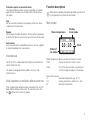
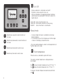
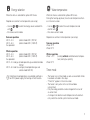
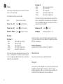
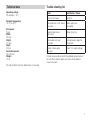
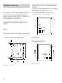
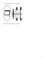
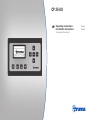
CP 25-UK
Operating instructions
Installation instructions
To be kept in the vehicle!
Page 2
Page 8
CP 25-UK
Table of contents
Operating instructions
Operating instructions
Symbols used ........................................................................
Safety instructions ............................................................
Intended use ..........................................................................
Initial operation or activation after a power cut ...................
Function description ..........................................................
Main screen ...........................................................................
On / Off ..................................................................................
Room temperature ................................................................
Energy selection ....................................................................
Water temperature ................................................................
Setup .....................................................................................
Maintenance .........................................................................
Disposal .................................................................................
Technical data .....................................................................
Trouble-shooting list ..........................................................
2
2
3
3
3
3
4
4
5
5
6
6
6
7
7
Installation instructions
Please be sure to read the instructions for installation
and use before attempting to connect and use this
device!
Symbols used
Symbol indicates a possible hazard.
Comment including information and tips.
Safety instructions
To protect you from electrical shocks, injury or burns
the following basic safety principles must be observed
when using electrical devices. Please read and follow these
instructions before using the device.
Panel ...................................................................................... 8
Installation
Ensure that the devices are positioned safely and cannot fall
down or over. Always position the cables to ensure they do
not pose a tripping hazard. Do not expose electrical devices to
rain. Do not operate electrical devices in damp or wet environments. Do not operate electrical devices close to flammable
liquids or gases. Position the devices so that they are out of
the reach of children.
2
Protection against an electrical shock
Only operate devices whose casings and cables are undamaged. Ensure the cables are installed safely. Do not pull on
the cables.
Use
Do not use electrical devices for purposes other than those
stated by the manufacturer.
Function description
More details regarding the operating modes you will find
in the operating instruction of your Combi.
Main screen
Repairs
Do not repair or modify the device. Please contact your dealer
or the Truma Service (see service manual or www.truma.com).
Accessories
Only use accessories and additional devices that are supplied
or recommended by the manufacturer.
Room temperature
Display
timer mode
10:10
Clock
Status of
the heater
Intended use
The CP 25-UK is a digital operating / display and control unit
for the Combi 4 E / 6 E.
Room temperature: Display on when the heater is active
Timer:
Display on when the timer is active
Clock:
The device is designed to be installed in caravans and
motorcaravans.
Initial operation or activation after a power cut
Only if the clock has been set, otherwise
the Truma logo will appear in the display
Status of the heater:
H:
Set room temperature (e.g. 18 °C)
EG:
Energy selection (E = Electro, G = Gas)
W:
Set water temperature
After the operating voltage has been connected, the unit will
beep and the display remains dark. To switch on, press the
and the main screen will appear.
key
3
On / Off
– Display and heater is switched on and / or off
– The clock is shown when the time is set
– After an interruption in the operating voltage, the display
and the heater are switched off. If the time is shown, this
needs to be set.
Green LED shines when the heater is on
Green LED flashes when the heater is after-running
Red LED
shines when there is a malfunction
Manual mode
Selection key upwards to select functions or
set values
Selection key downwards to select functions or
set values
– In manual mode, the heater is controlled via the 4 keys
below the display.
– It is not necessary to set the time because the Truma logo
is shown in the display instead of the time.
A pre-selection between summer / winter operation must
be made via the setup.
Selection key backwards to select values
Room temperature
Selection key forwards to select values
When the menu is selected the yellow LED shines.
The current set room temperature is displayed and can
be changed.
Key
Key
increases the room temperature (max. 30 °C) by 1 °C
reduces the room temperature (min. 5 °C) by 1 °C
A change in the room temperature needs to be confirmed
with .
4
Energy selection
When the menu is selected the yellow LED shines.
Water temperature
Depends on summer / winter operation (see setup)
When the menu is selected the yellow LED shines.
During the heating-up phase, the set water temperature flashes in the main screen.
– Use key
or
to select the energy source and confirm
with .
– Bar shows current mode
or
to select the water temperature and
– Use key
confirm with .
– Bar shows current mode
Summer operation
230 V – 4 A
(electro mode 230 V, 900 W)
230 V – 8 A
(electro mode 230 V, 1800 W)
Gas powered
Depends on summer / winter operation (see setup)
Winter operation
230 V – 4 A
(electro mode 230 V, 900 W)
230 V – 8 A
(electro mode 230 V, 1800 W)
Gas powered
230 V – 4 A and gas (mixed operation gas and electro mode
900 W)
230 V – 8 A und Gas and gas (mixed operation gas and
electro mode 1800 W)
If electro or mixed operations are selected and there is
no 230 V power supply, the heating will not function.
Summer operation
Water 40 °C
Water 60 °C
Winter operation
Water > 0 °C
(heating without controlled water temperature, heating has priority)
Water 60 °C
Timer mode
– The heater runs in timer mode as soon as one or both timers
have been activated in the setup
– “Timer On” appears in the main screen
– The heater is only active in the set time window
(active timer)
– Only the energy selection can be changed in the case of
an active timer
– A change in the room or water temperature will automatically switch the control system into manual mode
5
Setup
In the main screen display you can enter the setup
menu via the setup key.
Set timer 2
Back
Start
Stop
Water
Temp
(Return to main screen)
(Set start time)
(Set stop time)
(Set water temperature)
(Set room temperature)
The following settings can be made:
Back
(return to main screen)
Timer 1 on / off
(select
on / off wählen)
The timer settings can be made every day until the
timer is switched off. If the room or water temperature is changed outside the timer menu, the timer is
automatically switched off.
Timer 2 on / off
(select
on / off wählen)
Buzzer on / off (select
summer / winter)
Backlight
Summer / Winter (select
on / off)
(brightness levels 0 – 9)
Set clock
Set timer 1
Back
Start
Stop
Water
Temp
(Return to main screen)
(Set start time)
(Set stop time)
(Set water temperature)
(Set room temperature)
The timer settings can be made every day until the
timer is switched off. If the room or water temperature is changed outside the timer menu, the timer is
automatically switched off.
If no action is taken, the display switches back to the
main screen after a few seconds. The lighting switches
off after a short delay.
Further information
see operating instructions Combi 4 E / Combi 6 E
Maintenance
Clean the panel with a dry and fluff-free cloth.
Disposal
The device must be disposed of in line with the administrative
regulations of the respective country in which it is used.
National regulations and laws (in Germany, for example, the
End-of-life Vehicle Regulation) must be observed.
6
Technical data
Operating voltage
DC voltage 8 – 16 V
Ambient temperature
-20 °C to +60 °C
Front panel
Plastic
Width
190 mm
Height
110 mm
Depth
29 mm
Cutout dimensions
165 x 90 mm
Weight
170 g
Trouble-shooting list
Fault
Rectification / Cause
Clock is not shown
Set clock
Activated timer is not shown
any more
Power supply was
interrupted
Room temperature is
not shown
Heater not active
Device does not react
any more
Interrupt power supply for
10 seconds
Heater / display does
not react
Check 12 V supply voltage
If these measures do not rectify the problem, please contact
the next Truma Service point (see Truma service book or
www.truma.com).
The right to effect technical modifications is reserved!
7
Installation instructions
The installation in the vehicle must comply with the technical
and administrative provisions of the respective country in
which it is used (e.g. EN 1648, VDE 0100-721). National regulations and guidelines must be observed.
In other countries always observe the respectively valid
regulations.
Panel
– Connect the cable (TIN-Bus) to the display and lead toward
the heater.
– Connect the 12 V plug and connect with the 12 V operating
voltage. Secure the plus cable with a 1 A fuse.
– Connect GSM module (optional). The heater can be
switched on remotely via the GSM module.
12 V
+
-
2 x TIN-Bus
GSM
Install the panel in a place that is protected from damp and wet.
View from the back
– Prepare an installation opening for the display.
– Attach the panel with 4 screws.
6.5
110
90
max. 4
165
2 x TIN-Bus
GSM
13.5
190
View from the front
Dimensions in mm.
8
+-
– Press the frame of the panel until it clicks into position.
The right to effect technical modifications is reserved!
9
In Germany, always notify the Truma Service Centre if
problems are encountered; in other countries the relevant
service should be contacted (see Truma Service Booklet or
www.truma.com).
34020-98600 · 01 · 07/2011 · Fo · ©
Having the equipment model and the serial number ready
(see type plate) will speed up processing.
Sales and Service in UK and Eire:
Truma (UK) Limited
2000 Park Lane, Dove Valley Park
Foston
South Derbyshire DE65 5BG
Service
telephone: (01283) 58 60 20
telefax:
(01283) 58 60 29
[email protected]
www.trumauk.com