1
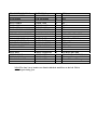
TRACE ELLIOT
SERVICE MANUAL NO. SM00019
ISSUE 1
Date:
Product Code :
Model No :
Technical File No :
October 28, 1996
T0105
V-Type V4 Head
TE00019
Issued by:
Trace Elliot Limited.
Blackwater Trading Estate
The Causeway, Maldon
Essex CM4 4GG.
C12-PCB-VTYP-C/Hx1.
V-TYPE COMBO/HEAD PREAMP MAIN BOARD.
ISSUE 1 INSERTION LIST. ANDY EWEN 11/8/98.
DESCRIPTION
PART CODE
QTY
WHERE USED
PCB PC00008 ISSUE 2
ZENER DIODE 27V
DIODE
RES 2.5W 4K7
RES 2W 100K
RES 1/2W 10K
ZERO OHM LINK
RES 1/4W 100K
RES 1/4W 100R
RES 1/4W 10K
RES 1/4W 10M
RES 1/4W 150K
RES 1/4W 1K5
RES 1/4W 1M
RES 1/4W 27K
RES 1/4W 330K
RES 1/4W 47K
RES 1/4W 560K
RES 1/4W 560R
RES 1/4W 5K6
RES 1/4W 8K2
73-PCB-PC00008
72-D-BZX55C27V
72-D-IN4007
72-RWW4K7-2.5W
72-RC100K-2W
72-RC10K-.5W
72-RCZERO
72-RM100K
72-RM100R
72-RM10K
72-RM10M
72-RM150K
72-RM1K5
72-RM1M
72-RM27K
72-RM330K
72-RM47K
72-RM560K
72-RM560R
72-RM5K6
72-RM8K2
1
1
10
1
4
2
28
2
1
1
1
1
3
7
1
1
8
1
2
1
1
ZD1
D1-D10
R35
R8 R10 R17 R20
R9 R36
AS MARKED
R2 R5
R40
R24
R14
R23
R6 R16 R18
R3 R4 R7 R12 R15 R21 R22
R1
R13
R25-R32
R11
R33 R34
R37
R19
CAP 1uF POLY BOX
CAP 1uF ELEC RADIAL
CAP 10uF ELEC RADIAL
72-C1-250VP
72-C1-63VER
72-C10-35VER
1
2
2
CAP 10uF ELEC RADIAL
CAP 1000uF ELEC RAD.
CAP 100N POLY BOX
CAP 100P CER DISC
CAP 150P CER DISC
CAP 200P Polystyrene
CAP 22uF ELEC AXIAL
CAP 22N POLY BOX
CAP 47uF ELEC RADIAL
CAP 470uF ELEC RAD.
CAP 470N POLY BOX
CAP 47N POLY BOX
CAP 47N POLY BOX
CAP 4N7 POLY BOX
CAP 100uF ELEC RAD.
72-C10-63VER
72-C1000-63VER
72-C100N-250VP
72-C100P-100VCD2
72-C150P-50VCD
72-C200P-630VPA
72-C22-450VEA
72-C22N-400VP
72-C47-63VER
72-C470-63VER
72-C470N-250VP
72-C47N-100VP
72-C47N-400VP
72-C4N7-400VP
72-CAP-100400V
2
1
5
2
1
1
2
2
2
1
1
1
2
1
1
C2
C14 C15
MOD ACROSS R28 & R29
+ve legs nearest IC1.
C16 C17
C22
C4 C24 C25 C26 C27
C18 C28
C8
C3
C20 C21
C12 C13
C9 C10
C23
C11
C1
C5 C7
C6
C19
TRANSISTOR BC549C
8-WAY SOCKET
IC RC4558P
72-TBC549C
72-SOCKET-8W
72-IC-RC4558P
1
1
1
TR1
FOR IC1
IC1
POT A 1MEG
POT A 250K
POT A 25K
POT A25K PULL SWITCH
73-POT-A1M
73-POT-A250K
73-POT-A25K
73-POT-A25K-PS
1
2
1
1
P1
P2 P4
P5
P3
MINI TOGGLE SWITCH
73-SWT-M-TGL-PCB
4
SW1 SW3 SW4 SW5
2-WAY HEADER 0.1”
8-WAY HEADER 0.2”
VALVE BASE 9-WAY
XLR PLUG NEUTRIK
JACK SOCKETS
72-HEAD-2W
72-HEAD-8W
73-VAL-SOCKET
73-XLR-PCB-M-N
72-SKT-JCKBNBG
4
1
2
1
2
HP1-HP4 (SEE NB1)
PL1
VT1 VT2
XLR1
SK1 SK2
FLYLEAD
SIGNAL LEAD
SIGNAL LEAD
LEAD FOR LAMP
C00-FLY-HEATER
LOOM-00275
LOOM-00276
LOOM-00277
1
1
1
1
ACROSS HP1-HP4
From L/0(F) to PC00009
From send/return to PC00009
From PL3 to 6.3V lamp
N.B.1 The four 2-way headers are fitted with their small face to the left. This is
with the pots facing you.
PROCEDURE FOR BIASING V4/V6
ISSUE 1 PS 31/8/99
1) Connect ‘BIAS KING’ valve plug/sockets to rear middle two valve
sockets on amplifier chassis.
2) Insert matched set of KT88’s into all positions.
3) Switch unit to Standby mode and allow valves to warm up for at
least 1 minute.
4) During this time connect unit to appropriate load and set all
controls to minimum.
5) Switch unit from Standby to fully On.
6) By observing the current read out on the LCD display of the BIAS
KING and switching between the two valves, adjust the quiescent
cathode current to give 30mA (+/- 2mA) on each valve. The trim
pots are accessible from the top of the chassis and can be
adjusted using a trimmer tool.
7) Switch unit to Standby and then Off.
8) When cool enough remove BIAS KING from between valves and
re-insert them into bases.
9) Turn to Standby again, warm up and then switch on.
10) Connect a signal generator to the INPUT and set up controls to
give maximum power output.
11) Check that this is an acceptable power for the unit in question
and that there is no excessive distortion.
12) Gently tap each valve with a screwdriver, signal on scope
should remain stable.
2