1
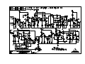
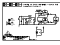
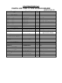
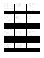
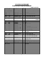
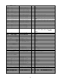
TRACE ELLIOT
SERVICE MANUAL NO. SM00080
ISSUE 1
Date:
Product Code :
Model No :
Technical File No :
July 13th, 2000
T0136
V8
TE00080
Issued by:
Trace Elliot Limited.
Blackwater Trading Estate
The Causeway, Maldon
Essex CM4 4GG.
cd0119x1.sch-1 - Tue Jul 11 17:20:27 2000
cd0120x1.sch-1 - Tue Jul 11 17:21:56 2000
C12-PCB-PC00121x2
PARTS LIST FOR V-TYPE V8 BACK BOARD
Description
PCB
Part Code
ISSUE 2 5/5/00 PS
Where Used
Qty
PC000121 issue B
1
72-RM560R
72-RM12K
72-RM22K
72-RM47K
72-RM330K
72-RM1M
2
1
2
5
1
1
R1
R4
R7
R5
R3
R6
R2
100p
100V axial
1u5 35V tant
72-C100P-100VCA
72-C1.5-35VT
2
2
C5
C3
22u 63V elect rad
72-C22-63VER
2
C1
C6
C4 (Insert C4 opposite
way round to normal)
C2
72-IC-RC4558P
1
IC1
72-HEAD-3W-2
1
FX1
¼” Mono Jack SKT
XLR Plug Neutrik
72-SKT-JCKBNBG
73-XLR-PCB-M-N
3
1
SK2 SK3 SK4
SK1
SWITCH
73-SWT-F2UEE
2
SW1 SW2
RESISTORS
560R
12K
22K
47K
330K
1M0
1W
1/4W
1/4W
1/4W
1/4W
1/4W
R8
R9
R13
R10 R11 R12
CAPACITORS
SEMICONDUCTORS
RC4558
CONNECTORS
3 way 0.1”
SOCKETS
C12-PCB-PC00123xC
PARTS LIST FOR V8 400W VALVE POWER BOARD
Description
PCB
Part Code
ISSUE C 2/3/00 PS
Where Used
Qty
PC000123 issue 1
1
RESISTORS
1R0
2R2
10R
47R
100R
680R
1K0
1K5
1/4W
1W
1/4W
1/4W
1/4W
1/4W
1/4W
1/4W
72-RM1R
72-RM2R2-1WATT
72-RM10R
72-RM47R
72-RM100R
72-RM680R
72-RM1K
72-RM1K5
1
2
1
1
1
1
2
8
3K3
10K
10K
15K
22K
27K
47K
47K
100K
220K
10R
1/4W
1/4W
1W
1/4W
1/4W
1/4W
1/4W
1W
1/4W
1W
4W
72-RM3K3
72-RM10K
72-RM10K-1WATT
72-RM15K
72-RM22K
72-RM27K
72-RM47K
72-RM47K-1WATT
72-RM100K
72-RM220K-1WATT
72-RWW10R-4W
1
2
5
1
3
1
4
2
3
3
8
2K2
4W
72-RWW2K2-4W
9
R53
R54
R59
R43
R50
R1
R48
R14
R36
R2
R33
R44
R51
R3
R52
R4
R8
R9
R39
R13
R27
R15
R28
R55
R49
R17
R37
R20
R38
R23
R35
R34
R45
R46
R47
R58
R41
R42
R5
R11
R10
R40
R16
R29
R18
R30
R6
R12
R56
R19
R31
R21
R32
R7
R22
R25
R24
R57
R26
Insert wire wound resistors away from
surface of PCB, with formed leads
PCB MOUNT FUSE
72-FUS-125MA-F
1
FS5
72-D-BZX55C15V
72-D-GP02-40
72-D-IN4002
72-D-IN4007
72-D-IN5408
1
2
4
5
4
Z1
D6
D14
D1
D8
DIODES
15V ZENER
GP02-40
1N4002
1N4007
1N5408
D7
D15
D9
D10
D18
D11
D12
D19
D13
D16
C27
C28
C24
C32
CAPACITORS
100n
330n
100V axial
50V axial
72-C100N-100VCA
72-C330N-50VCA
2
1
C3
C30
C4
100p
10n
22u
47u
1000u
1KV ceramic
400V poly box
160V elect radial
63V elect radial
35V elect radial
72-C100P-1KVCD
72-C10N-400VP
72-C22-100VER
72-C47-63VER
72-C1000-35VER
2
4
2
4
2
C5
C9
C1
C16
C22
C25
C19
C2
C17
C23
1
D17
2200u 35V elect radial
22u 450V elect radial
220u 400V elect radial
470u 400V elect radial
72-C2200-35VER
72-C22-450VER
72-CAP-220400V2
72-CAP-470400V
4
5
2
2
C14
C11
C10
C8
C15
C12
C29
C26
C33
C13
C34
C20
72-T2N3904
72-T2N3906
72-TBD647
72-LED-RED-3MM
3
2
1
4
TR1 TR4 TR5
TR2 TR3
TR6
(see below for heat sink)
D2 D3 D4 D5 (Bottom of PCB)
72-HEAD-3W-2
72-HEAD-3W-3
72-HEAD-10W
2
1
2
PL3 PL4
FAN1
PL1 PL2
72-SKT-JCKBNBG
72-SKT-JCKBBBG
73-XLR-PCB-F-N
1
1
1
SK2
SK3
SK1
73-SWT-SLIDER-DP
2
SW1 SW2
72-PRESET-47K-V
2
RV1
RV2
PCB panel access
32mm PCB fuse clip
Small PCB fuse clip
72-FUS-HLD-PCB
72-FUS-HLD-PDB-2
72-FUS-HLD-PCB-4
4
2
2
FS1
FS6
FS8
FS2
FS7
CRIMP CONNECTORS
72-CRIMP-PCB-TAB
22
TX1-17
STBY1-4
BIAS TEST POINTS
73-TERM-SCREW-M3
3
BIAS0
BIAS1
0V TEST POINT PIN
73-TERM-PIN
1
TP0
HEATER WIRING
C00-LEAD-V8-HTR
2
H1-H20
OCTAL VALVE BASES
73-VAL-SOCKET-2
8
V1-V8
TO220 HEATSINK
M3 SCREW
M3 WASHER
M3 WASHER
M3 NUT
INSULATING KIT
Heat sink compound
G13-HS-TO220-14H
71-SCR-M3X12PPB
71-WAS-M3INTSP
71-WAS-M3ABLK
71-NUT-M3ZINC
72-MOS-PAD-TO220
1
1
1
1
1
1
TR6
Part of heat sink assembly
“
“
“
“
Between TR6, heat sink & chassis
C21
(PHILIPS 157 46471)
SEMICONDUCTORS
2N3904
2N3906
BD647
3mm RED LED
CONNECTORS
3 way 0.1”
3 way 0.2”
10 way 0.1”
SOCKETS
¼” MONO
¼” STEREO
XLR FEMALE PCB
SWITCHES
POTENTIOMETERS
(301-190 VDC)
FUSE HOLDERS
2
FS3
FS4
(check insertion)
EARTH
BIAS2
C12-PCB-V8-PREAMP
PARTS LIST FOR V8 PREAMP
Description
Part Code
Qty
PCB
PC00120 issue 1
*** = formerly obsolete
1
ISSUE 1 4/5/00 PS
Where Used
(Part to be used when old part is used up)
A.I. MACHINE
100R
220R
470R
470R
1K0
1K0
1K5
1/4W
1W
1/4W
1W
1/4W
1W
1/2W
72-RM100R
72-RM220R-1WATT
72-RM470R
72-RM470R-1WATT
72-RM1K
72-RM1K-1WATT
72-RM1K5-.5W***
2
5
1
5
2
1
7
R19
R11
R81
R9
R48
R25
R41
R20
R13 R30 R33 R36
3K3
4K7
7K5
8K2
10K
10K
22K
47K
47K
82K
100K
100K
1/4W
1/4W
1/4W
1/4W
1/4W
1W
1/4W
1/4W
1W
1W
1/4W
1W
72-RM3K3
72-RM4K7
72-RM7K5
72-RM8K2
72-RM10K
72-RM10K-1WATT
72-RM22K
72-RM47K
72-RM47K-1WATT
72-RM82K-1WATT
72-RM100K
72-RM100K-1WATT
2
1
1
1
3
1
1
3
6
1
3
9
R75
220K
220K
470K
1M0
1/4W
1W
1/4W
1/4W
72-RM220K
72-RM220K-1WATT
72-RM470K
72-RM1M
6
4
5
13
3M9
10M
1/4W
1/4W
72-RM3M9
72-RM10M
1
10
72-C47N-100VCA
72-C100N-100VCA
72-D-IN4148
72-D-IN4007
2
2
7
3
R73
R85
R67
R5
R8
R53
R77
R22
R38
R83
R15
R16
R74
R17
R39
R3
R10
R51
R63
R1
R43
C23
C35
D1
D3
R91
R12 R29 R32 R35
R93
R52 R55 R57 R62 R66 R69
(72-RM1K5)
47n
100V axial
100n
100V axial
1N4148
1N4007
NOT FITTED
1
R79 R86
R27 R28
R70 R72 R80 R89 R92
R59
R50
R88
R18
R40
R31
R23
R82
R84 R96
R54 R56 R60 R64 R65
R2
R61
C48
C36
D2
D4
R95
R4 R6
R71
R7
R14 R34
D5 D6
D10
D7
D8
R21
R46
R58
R24
R87
R44
R68
R78
R26
R90
R47 R76
R97
R42 R45 R49
R94 R98
D9
2nd STAGE
82R
100p
150p
200p
4W
1KV ceramic
630V poly
630V poly
72-RWW82R-4W
72-C100P-1KVCD
72-C150P-630VPS
72-C200P-630VPA
1
2
1
1
R37
C27 C30
C3
C8
470p
4n7
22n
630V poly
400V poly box
400V poly box
72-C470P-630VPA
72-C4N7-400VP
72-C22N-400VP
4
1
8
47n
100n
220n
400V poly box
400V poly box
250V poly box
72-C47N-400VP2
72-C100N-400VP
72-C220N-250VP
5
7
1
C1
C7
C16
C47
C5
C9
C31
1u5
2u2
15u
35V tant
63V elect rad
63V elect axl
72-C1.5-35VT
72-C2.2-63VER
72-C15-40VEA***
1
1
13
C39 C42 C43
NEW PART
C17 C22 C33 C40 C44 C45
C6 C25 C28 C38
C20 C49 C50 C51 C52 C53
C41
C2
C4 C12 C13 C15 C18 C19 C21
C24 C26 C29 C32 C34 C46
(72-C2263VER)
47u
22u
63V elect rad
450V axial
72-C47-63VER
72-C22-450VEA
2
1
C14 C37
C11
72-FET-J-112P
72-LED-BLU-3MM
72-LED-RED-3MM
1
1
1
TR1
LED2
LED1
72-HEAD-3W
72-HEAD-10W
72-SKT-JCKBNBG
1
2
2
HTR1
PL1 PL2
SK1 SK2
73-SWT-F2UEE
3
SW1 SW2 SW3
1M0 Log
1M0 Log Pull Switch
100K Log
250K Log
25K Log Pull Switch
50K Lin
73-POT-A1M
73-POT-A1M-PS
73-POT-A100K
73-POT-A250K
73-POT-A25K-PS
73-POT-B50K
1
1
2
2
1
1
RV1
RV2
RV3 RV8
RV4 RV6
RV5
RV7
RELAY Omron G5V-1
73-RELAY-5V-SPCO
5
RL1 RL2 RL3 RL4 RL5
B9A PCB base gold
73-VAL-SOCKET-G
8
V1 – V8
SEMICONDUCTORS
J112 FET (selected)
Blue 3mm
LED
Red 3mm
LED
CONNECTORS
3 way 0.1”
10 way 0.1”
¼” Mono Jack SKT
SWITCH
POTENTIOMETERS
2 track modifications
2
(on underside of PCB)
V-TYPE V8 TEST PROCEDURE
ISSUE A PS 2/3/2000
Initial Checks
1)
Check the polarity of all electrolytic capacitors and diodes on power board.
2)
Install all fuses and valves (see accompanying sheet).
3)
Set all rotary controls to midway position, all push switches out. (front and rear)
Set to FULL POWER and turn both BIAS ADJUST pots fully clockwise.
Set rear panel mains switch to OFF and front panel toggle to STANDBY.
Connect unit to (4Ω) load station. Connect mains socket to variac set at minimum.
4)
Switch unit to standby mode. Gradually turn up the variac to the appropriate voltage.
Green lamp and front and green mains switch will light up.
Voltage Tests
5)
Check following Test Points (TP):-
(all DC TP’s are w.r.t. TP0 0V)
TP1/TP2
TP3
TP4
TP5
TP6
6.3vac ±0.6vac
24V ±1V
12V ±0.5V
-60V ±3V
-60V ±3V
6)
Turn variac to minimum. Switch from STANDBY to ON, return variac to correct voltage.
7)
Set bias as follows:Insert black DMM probe (-) into 0V hole, red (+) into V1 on rear panel.
Slowly turn left hand ADJUST control to give a reading of 0.300V ±0.03V.
Insert black probe into V2, carefully rotate the right hand ADJUST to give 0mV ±0.01V.
Repeat above procedure as appropriate until settings are correct.
(The setting of the two ADJUST pots interact)
8)
Check biasing of other valves, if necessary adjust bias again to bring all valves within the
0.270 – 0.330V range.
V1 - TP15
V2 - TP16
9)
V3 - TP17
V4 - TP18
V5 - TP19
V6 - TP20
Check the following Test Points:TP7
TP8
TP9
TP10
TP11
TP12
TP13
TP14
(CT)
(G2)
(HT1)
(HT2)
(HT3)
(HT4)
(HT5)
(HT6)
1
690V
360V
330V
295V
270V
270V
240V
225V
±15V
±15V
±15V
±15V
±12V
±12V
±10V
±10V
V7 - TP21
V8 - TP22
Sine wave tests
10)
Insert 1Khz, -20dBu (77mVrms) sine wave into the PASSIVE INPUT.
Turn up GAIN I fully then adjust MASTER until the output starts to clip.
Check the power is >400W (40vrms @ 4Ω
Ω ) and the EM84 display valve is fully lit.
Using screwdriver handle gently tap each valve and check for microphony and instability.
11)
Switch to HALF POWER mode. (on rear panel)
Check there is a reduction in output power (~25vrms @ 4Ω
Ω ). Return to FULL POWER.
12)
Turn GAIN I back to half way. Insert sig. gen. lead into ACTIVE INPUT and then back into
PASSIVE. Check that when in ACTIVE the output level approximately halves.
13)
Press BRIGHT, signal should increase slightly.
14)
Pull out GAIN II. Check signal on scope is as shown:Adjust GAIN II & LEVEL controls to check smooth operation.
Return to half way.
15)
Push DEEP. Signal should increase slightly. Push out again.
16)
Turn TREBLE, MIDDLE & BASS to minimum.
Turn BASS to maximum, check signal on scope:Return to minimum.
17)
Turn MIDDLE to maximum, check signal on scope:Return to minimum.
18)
Turn TREBLE to maximum, check signal on scope:Return controls back to half way.
Push in GAIN II. Signal should be clean again.
19)
Switch on COMPRESSOR, signal should increase slighlty.
Turn up LEVEL, the blue LED should be lit just before full.
Turn off COMPRESSOR, blue LED should fade out.
Rear Panel
20)
Check that none of the rear LED’s are lit.
Using a screwdriver remove each fuse, one at a time. Check each LED lights up.
21)
Check correct functionality of 2 way foot switch socket.
Tip should switch from GAIN I to GAIN II, ring switches COMPRESSOR on/off.
22)
Check there is an output at the correct level from the following sockets:DI OUT – (POST/GROUND)
DI OUT – (PRE/GROUND)
LINE OUT
SEND
~20mV p/p
~350mV p/p
~1.2V p/p
~200mV p/p
23)
Turn MASTER control to minimum and switch unit to STANDBY.
Connect output to appropriate speaker cabinet and bass guitar
Aurally test main features of each channel and check for any excessive hum or noise.
24)
Connect to load & sig. gen., set up for full power and soak test for approx. 30 minutes.
End of test.
2


![Trace Elliot V4[1]](http://vs1.manualzilla.com/store/data/006017218_1-da9c5d9940e3b4825dbcd5847480f1a7-150x150.png)