1
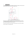
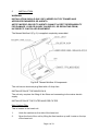
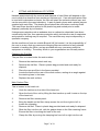
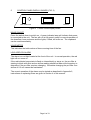
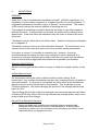
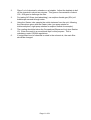
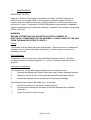
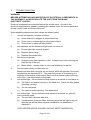
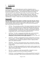
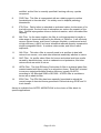
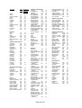
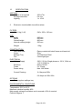
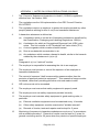
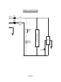
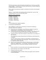
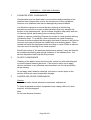
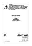
Caution:
Please read this Manual thoroughly.
If you do not understand or are unsure of any
information contained in this Manual please
contact your Agent or BIOQUELL for
clarification.
OPERATING MANUAL
ASTEC
MONAIR MINIFLOW 8
(TM190-O&M-001)
Revision 3
part of BIOQUELL (UK) Limited
© BIOQUELL UK LTD
52 Royce Close
West Portway, Andover
Hampshire, SP10 3TS
Tel: 01264 835835
Fax: 01264 835836
Email:[email protected]
http://www.bioquell.com
Page 1 of 31
1
INTRODUCTION
The Monair Miniflow 8 has been designed to produce a compact unit that will provide
operator safety with good access to the working surface.
Figure 1 Monair Miniflow 8 Airflow Schematic
The main work area has a downflow of >0.4 m/s to provide containment of fumes.
The stainless steel work surface can be removed to clean away any spills from the
tray. The airflow schematic is shown in Figure 1.
The head unit contains the mains switch, low airflow alarm, carbon filter and lights.
The unit contains 1 x 8 kg carbon filter.
Page 3 of 31
2
INSTALLATION
WARNING:
INSTALLATION SHOULD ONLY BE CARRIED OUT BY TRAINED AND
APPROVED ENGINEERS OR AGENTS.
ASTEC MICROFLOW OR ITS AGENTS CANNOT ACCEPT RESPONSIBILITY
FOR DAMAGE, LOSS OR INJURY CAUSED BY, OR RESULTING FROM,
INCORRECTLY INSTALLED EQUIPMENT.
The Monair Miniflow 8 (Fig. 2) is supplied completely assembled.
Figure 2 Monair Miniflow 8 Components
The unit has an electrical plug fitted with a 3 Amp fuse.
INSTALLATION OF THE MINIFLOW 8
The unit only requires the fitting of the filters and connecting to the mains electric
supply.
INSTALLATION OF THE FILTER AND PRE-FILTER
Main Carbon Filter
This is located in the head unit.
1.
Undo the catches on the side of the head unit.
2.
Open the front of the unit by lifting the front section up until it rests on the top
of the head unit.
Page 4 of 31
3.
Remove the filter access panel.
4.
Bring the handle on the filter clamp across the unit from right to left, to
loosen the clamping.
5.
Slide the filter into the unit, with the gasket down on the filter retaining frame.
Ensure the filter is touching the back of the unit.
6.
Clamp the filter by moving the clamping bar from left to right into the unit.
7.
Replace the front access panel.
8.
Lower the front section of the head into place and secure the catches in
place.
Pre-filter
The pre-filter is located under the work surface.
1.
Remove the stainless steel work tray.
2.
Place the pre-filter in the frame provided.
3.
Locate the frame at the rear of the work surface, resting at an angle against
the retaining bars in the base.
4.
Replace the work surface.
Page 5 of 31
3
GENERAL OPERATING INSTRUCTIONS
A.
The downflow fume enclosure may only be operated with the correct filter
installed for the application. Refer to sections 9 and 10 of this manual for
further information. If in doubt, call Bioquell UK Ltd directly, or contact your
local dealer.
B.
To start the unit, switch the power switch on. The fan will automatically run
to give 0.4 m/s downflow at the worksurface.
C.
Check the airflow and filter saturation on a regular basis. Section 6 of this
manual describes monitoring systems in greater detail and discusses
COSHH requirements.
D.
The unit has a stainless steel work tray, which can be removed to clean
under the perforated area.
E.
It should be noted that filter blocks do not absorb carbon monoxide or
hydrogen. However small quantities (such as used in schools) will not
present a hazard because of the large dilution factor from the airflow through
the unit and retardation of the chemical in the filter matrix.
F.
Astec downflow fume enclosures are designed to handle fumes and vapours
given off during normal laboratory procedures. These will be at the ppm
level in the airstream entering the filter block. It is NOT recommended that
large quantities of solvents or acids should be boiled off in the downflow
fume enclosure.
G.
Always keep a spare set of filters available.
H.
High concentrations of fumes entering the filter block may temporarily reduce
the filtration efficiency. For this reason any major spillage within the
downflow fume enclosure should be cleared up immediately, preferably
using spillage absorption granules rather than tissue paper which may
aggravate the evaporation of toxic fumes from the spillage area.
I.
Following a major spillage, the main filters must be changed, as the heat of
wetting may reduce filter efficiency. After stabilisation, the old filters can
normally be re-used, provided saturation has not been reached.
J.
The electrical equipment in the cabinet including light fittings and control
equipment are in separate enclosures, on the clean side of the filter. The
equipment should not be used in a flammable room atmosphere. Specially
modified equipment can be provided for use in solvent rooms. Contact
Bioquell UK Ltd or your local dealer/distributor for further information.
Page 6 of 31
4
FITTING AND REMOVAL OF FILTERS
Hazards associated with the removal and disposal of used filters will depend on the
use to which the downflow fume enclosure has been put. If an activated carbon filter
is used with hydrocarbon solvents, the filter will retain the solvents without loss, and
can be removed in the open laboratory. A pair of plastic gloves and a plastic bag are
supplied with each filter. The plastic gloves should be used when removing filters.
The used filters should be placed in the plastic bag and sealed prior to waste
disposal, preferably by incineration.
If dangerous materials such as asbestos dust or radioactive chemicals have been
contained by the filter, then operator protection which includes the use of respirators
and protective clothing may be required. The used filter may require disposal by a
specialist company.
As the conditions of use are outside Bioquell UK Ltd control, it is the responsibility of
the user to ensure that any personnel changing filters are advised of any potential
hazards in handling the filters, and are provided with any necessary protective
equipment or clothing. The safety officer in your organisation can normally advise.
Changing the Pre-filter
The pre-filter is located under the work surface.
1.
Remove the stainless steel work tray.
2.
Remove the old filter. Place in plastic bag provided and seal ready for
disposal.
2.
Place the new pre-filter in the frame provided.
3.
Locate the frame at the rear of the work surface, resting at an angle against
the retaining bars in the base.
4.
Replace the work surface.
Main Carbon Filter
This is located in the head unit.
1.
Undo the catches on the side of the head unit.
2.
Open the front of the unit by lifting the front section up until it rests on the top
of the head unit.
3.
Remove the filter access panel.
4.
Bring the handle on the filter clamp across the unit from right to left, to
loosen the clamping.
5.
Remove old filter. Place in plastic bag provided and seal ready for disposal.
6.
Slide the filter into the unit, with the gasket down on the filter retaining frame.
Ensure the filter is touching the back of the unit.
7.
Clamp the filter by moving the clamping bar from left to right into the unit.
Page 7 of 31
8.
Replace the front access panel.
9.
Lower the front section of the head into place and secure the catches in
place.
Page 8 of 31
5
CONTROL PANEL/DISPLAY BOARD (FIG. 3)
LOW AIRFLOW
HOUR COUNTER
ON/OFF
Figure 3 Control Panel/Display Board
MAINS ON/OFF
Press the switch down to switch on. A green indicator lamp will indicate that power
is connected to the unit. The fan will run at full speed, ready for normal operation of
the downflow fume enclosure and the lights, if fitted, will come on. The cupboard
can be used immediately.
HOUR METER
This indicates the total number of hours running time of the fan.
LOW AIRFLOW ALARM
The alarm is a red light located at the front of the unit. In normal operation, the red
light will not come on.
If the red indicator lamp starts to flash on intermittently or stays on, the pre-filter is
starting to block with dust and an airflow reading should be taken at the aperture to
determine if the pre-filter requires changing. We advise changing the pre-filter if an
airflow of 0.3 m/s cannot be maintained.
The correct operation of the alarm may be tested as described in Appendix 2,
instructions on replacing filters are given in Section 4 of this manual.
Page 9 of 31
6
MONITORING
GENERAL
Under the “Control of Substances Hazardous to Health” (COSHH) regulations, it is
mandatory to check safety equipment at “suitable intervals” for correct operation. A
suggested maintenance schedule is given in Section 7 of this manual. This section
of the manual reviews the manual methods of checking the unit.
The purpose of monitoring is to detect when the pre-filters or main filters cease to
operate effectively. If the pre-filters are blocked, the airflow will be reduced at the
worksurface. If the main filters are saturated, they will cease to remove the fumes
effectively.
The Monair units are fitted with a low airflow alarm. Details for testing and calibration
are in Appendix 2.
The Monair units do not have any filter saturation detectors. You should carry out a
manual check of filter saturation once every three months, as described below.
If an odour is noticed, it is sensible to check the unit. However, it must be
remembered that the sense of smell is very sensitive for some chemicals (e.g.
ammonia or hydrogen sulphide) and a slight smell does not mean that the exhaust
levels of chemical have approached the maximum acceptable concentration.
MANUAL MONITORING
Manual monitoring should be carried out yearly to check the integral systems on the
unit.
Airflow Measurements
An anemometer should be used to check the airflow (face velocity) at the
worksurface. Any suitable anemometer may be used, including hot wire, propeller or
vane anemometer. A minimum of six readings should be taken at the worksurface.
Note the result in a record book kept for this purpose. This is mandatory under
COSHH regulations. We advise changing the pre-filter if the average airflow drops
below 0.3 m/s.
The pre-filters will normally need to be changed more frequently than the main filters.
A blocked HEPA filter (where fitted) is also indicated by reduced airflow, which is not
restored after a pre-filter change.
Manual Filter Saturation Detection
1.
Select a suitable test chemical and matching Gastec sampling tube.
Examples include alcohols, toluene, trichloroethylene, or any suitable
chemical in routine use in the downflow fume enclosure, provided it is well
adsorbed and is not dangerously toxic.
Page 10 of 31
2.
Place 3 ml of chemical in a beaker on a hotplate. Adjust the hotplate to boil
off the chemical in about two minutes. This gives a concentration of about
100 - 200 ppm to challenge the filter.
3.
For testing ACI filters (acid adsorbing), use sulphur dioxide gas (SO2) at 1
bubbles per second through water.
4.
Using the Gastec tube, sample the outlet airstream from the unit, following
the instructions given with the Gastec tube (one pump stroke for
trichloroethylene, eight pump strokes for sulphur dioxide for example).
5.
The reading should be below the Occupational Exposure Limit (see Section
10). Enter the result in a record book kept for this purpose. This is
mandatory under COSHH regulations.
6.
If a significant level of chemical is noted in the exhaust air, the main filter
should be changed.
Page 11 of 31
7
MAINTENANCE
IMPORTANT NOTICE
Under the "Control of Substances Hazardous to Health" (COSHH) regulations,
effective from 1st October 1989, it is mandatory to maintain written records of
checks, tests and repairs carried out on safety equipment, and these records must
be kept for 5 years. A summary of COSHH Regulations are provided in Appendix 1.
Regular maintenance will reduce the possibility of hazard to the operator and prolong
the life of the unit.
WARNING:
BEFORE ATTEMPTING ANY INSPECTION OR REPLACEMENT OF
ELECTRICAL COMPONENTS IN THE ASSEMBLY, ALWAYS ISOLATE THE UNIT
FROM THE MAINS ELECTRICITY SUPPLY.
Airflow
The Monair units are fitted with a low airflow alarm. With this model you should test
the alarm once a year as described in Appendix 2 of this manual, to ensure it is
operating correctly.
Filter Saturation
The Monair units do not have any filter saturation detection systems. The filter
condition should be monitored regularly, i.e. every 3 months or more frequently if
required.
Cleaning and Inspection
You should carry out the following procedures at six monthly intervals:
1.
Remove the spillage tray (where fitted) and wash in dilute detergent solution.
2.
Wash the interior surface of the cupboard with dilute detergent solution.
3.
Inspect the cupboard frame and panels for mechanical damage.
The following checks should be made every 12 months:
1.
Check the condition of the electric cable and plug.
2.
The electrical earthing and insulation should be inspected by a qualified
electrician.
3.
Check the fan for correct running.
Page 12 of 31
8
TROUBLE SHOOTING
WARNING:
BEFORE ATTEMPTING ANY INSPECTION OF ELECTRICAL COMPONENTS IN
THE ASSEMBLY, ALWAYS ISOLATE THE UNIT FROM THE MAINS
ELECTRICITY SUPPLY.
Electrical components are mounted behind the control panel. Access to the
electrical components is gained by undoing the catches under the control panel and
raising it until it rests on the top of the unit.
Some possible problems and their causes are shown below:
1.
2.
3.
4.
Unit will not operate, no lights or airflow:
(a)
Check that unit is plugged in and switched on.
(b)
Check fuse in mains supply or plug (where fitted).
(c)
Check fuses in electrical input socket.
Unit operates, but the fluorescent light does not come on.
(a)
Ensure light tube correctly seated.
(b)
Replace starter lamp.
(c)
Replace fluorescent tube.
Fan does not operate.
(a)
Change motor start capacitor on fan. Access to fan is by removing the
plate on top of the unit.
(b)
Motor failure - contact Astec or your local distributor for advice.
Fan operates initially, but then cuts out.
Motors are fitted with a thermal cut-out device, which will operate if the motor
temperature rise exceeds 95°C. The most likely cause of overheating is a
blockage of the airflow, either at the filters or at the exhaust outlet at the top
of the unit. Low airflow alarm will operate.
5.
6.
Low airflow light - the red indicator lamp comes on at switch on and stays on.
(a)
The filter is not sealed correctly in the head unit. Check the filter gasket
is sealing correctly.
(b)
The fan has failed.
(c)
The alarm is malfunctioning - See Appendix 2.
Low airflow light - the red indicator lamp comes on at switch on, goes off,
then comes on again.
(a)
The pre-filter is blocked with dust.
(b)
If replacement of the pre-filters does not cause the red light to stay off,
then the low airflow alarm requires recalibration, as described in
Appendix 2.
FOR FURTHER ADVICE PLEASE CONTACT ASTEC MICROFLOW.
Page 13 of 31
9
FILTER TYPES
PRE-FILTERS
Filtrete pre-filter. This is a high performance pre-filter, designed to remove
particulates from the airstream. The filter material is based on electrets, which are
permanently charged di-electrics. They remove particulates from polluted air by
strong electrostatic forces generated by the fibres from which they are made.
The combination of strong electric charge and open structure provides a filter with
high efficiency, low airflow resistance and high loading capacity. Measured
efficiency figures for particles in the 0.5 - 2.0 micron range is 99%, with loading
capacities up to 113 g/m². Filtrete will remove fine particles, aerosols and mists.
MAIN FILTERS
Fourteen different types of filter media are available for the main filter bed. Most of
these are impregnated activated carbon, to provide a higher filter capacity for lower
molecular weight organic compounds and inorganic gases and vapours. A number
of filter efficiency studies have been carried out, and all results using single bed
filters show efficiencies very close to 100%.
1.
GP Filter. The most widely used filter in the range, primarily for solvent fume
removal. It is manufactured from coconut-shell based activated carbon of 510 mesh size and surface area up to 1300 m²/gm. Filtration is achieved by
the physical adsorption of molecules in the pores of the activated carbon by
Van de Waals forces. This filter will remove any chemical with a molecular
weight greater than 30 and a boiling point greater than 60°C.
2.
ACR Filter. This filter is impregnated with halide salts, and is used for the
high efficiency removal of radioactive iodine and methyl iodide. It is
frequently used for iodination reactions with low-level radioactive iodine, and
efficiencies in excess of 99.99% have been measured.
3.
ACM Filter. This filter is impregnated with iodine compounds for removal of
mercury vapour. The filter has been demonstrated to remove mercury from
a saturated airstream at ambient temperature to below 5 parts per billion
(ppb) in the exhaust airstream.
4.
AMM Filter. This filter is impregnated with copper compounds to efficiently
remove vapour from dilute ammonia solutions, and to remove low molecular
weight amines.
5.
ACI Filter. This alkali impregnated filter will neutralise volatile inorganic acid
vapours such as hydrochloric and hydrofluoric acids, and acid gases such as
sulphur and nitrogen dioxides.
6.
SUL Filter. A potassium iodide impregnated filter, designed to remove
hydrogen sulphide and low molecular weight mercaptans.
7.
CYN Filter. A multi-impregnated filter to a military specification, for removal
of hydrogen cyanide gas. Many cyanide compounds will evolve HCN gas if
Page 14 of 31
acidified, so this filter is normally specified if working with any cyanide
compound.
8.
FOR Filter. This filter is impregnated with an oxidising agent to oxidise
formaldehyde to formate salts. It is widely used in hospital pathology
laboratories.
9.
ETH Filter. Diethyl ether is adsorbed on activated carbon, but because of its
low boiling point, the local heat of adsorption can reduce the capacity of the
filter. Special impregnation allows a chemical reaction, which increases filter
capacity.
10.
MIL Filter. As the name implies, this filter is multi-impregnated to handle a
wide range of chemicals defined by the Ministry of Defence. It will efficiently
remove solvent fumes, acid fumes, hydrogen sulphide, cyanides and arsine
at high efficiency (>99%) but has a somewhat reduced capacity compared to
single impregnated filters. It contains noble metals, and is thus rather
expensive.
11.
OAL Filter. This odour filter is normally used in air purifiers to deal with
odours from excreta, urine and other materials essentially alkaline in nature.
12.
OAC Filter. Air purifier odour filters for human and animal acid type smells
caused by bacterial decay, such as cadaverine and putrescine, and other
odours which are acidic in nature.
13.
HEPA Filter. The High Efficiency Particulate Air filter is a pleated glass-fibre
material sealed with epoxy resin in an aluminium frame. Each filter is tested
to ensure a stated particulatle filtration efficiency (usually 99.997%)
according to US Standard 209B or BS 3928. A HEPA filter is sometimes
known as an absolute filter.
14.
EDU Filter. The EDU filter has been specially formulated to adsorb the
normal range of chemical fumes generated in Schools during GCSE and 'A'
level classes.
Advice is available from ASTEC MICROFLOW on the choice of filter block for
specific applications.
Page 15 of 31
10
UK OCCUPATIONAL EXPOSURE LIMITS 2000
The Updated Occupational Exposure Limits are available on
www.hse.gov.uk/coshh/table1.pdf.
The exposure limits are expressed in parts per million by volume (ppm)
under the following headings:
(a)
LTEL - Long Term Exposure Limit (8 hour time weighted average
reference period).
(b)
STEL - Short Term Exposure Limit (15 minute reference period).
Gastec and Dräger sampling tubes are available for most chemicals.
Page 16 of 31
11
CHEMICAL APPLICATIONS
INTRODUCTION
The table overleaf gives a list of common laboratory chemicals, together with the
filter recommended and an estimate of filter capacity.
The recommended filter is the main single-layer filter used for the application. It may
be possible to use other filters, such as the MIL filter or a Multi Layer filter. In all
cases the filter efficiency for a single layer filter will be close to 100%. Chemicals
marked * are poorly absorbed by all filters and should be used in small quantities
only. Their exhaust concentration may however be quite low due to dilution with air
and retardation in the filter matrix.
The filter capacity is given as the equilibrium saturation capacity, a standard test
procedure for activated carbon (ASTM-D3467). The capacity is expressed as the
final filter weight at saturation as a percentage of initial filter weight. In many cases
these values have been determined by experiment, in other cases estimated values
are used based on experience with activated carbon material and a knowledge of the
chemical structure. The actual capacity obtained will depend on the conditions of
use, but the breakthrough point to reach the OEL of the chemical may be up to 70%
of this value for normal input loadings.
Page 17 of 31
Chemical
Filter
Type
Equilibrium
Saturation
Capacity %
Acids
Acetic
Acetic anhydride
Acrylic
Butyric
Caprylic
Carbolic
Formic
Lactic
Osmium tetroxide
Palmitic
Phenol
Proprionic
Valeric
GP
GP
GP
GP
GP
GP
ACI
GP
GP
GP
GP
GP
GP
33
33
40
40
40
40
20
40
40
40
40
40
40
Alcohols
Ethyl
Amyl
Butyl
Cyclohexanol
Isopropyl
Methyl (methanol)
Propyl
GP
GP
GP
GP
GP
GP
GP
32
40
40
45
40
32
40
Aliphatic Hydrocarbons
Acetylene
GP
Iso-butane
GP
Butylene
GP
Butadiene
GP
Cyclohexane
GP
N-decane
GP
Ethane *
GP
Ethylene *
GP
N-heptane
GP
Heptylene
GP
Hexane
GP
Hexylene
GP
Methane *
GP
N-nonane
GP
N-octane
GP
N-octylene
GP
Pentane
GP
Propane *
GP
Propylene
GP
20
10
10
35
35
26
10
Aromatic Hydrocarbons
Benzene
GP
Napthalene
GP
Ninhydrin
GP
Styrene monomer
GP
Toluene
GP
Toluidine
GP
Xylene
GP
40
47
47
47
47
47
40
Esters
Butyl acetate
Cellosolve acetate
Ethyl acetate
Ethyl acrylate
Ethyl formate
Isopropyl acetate
Methyl acetate
Methyl acrylate
Methyl formate
Methyl methacrylate
40
45
40
45
40
45
40
45
40
45
GP
GP
GP
GP
GP
GP
GP
GP
GP
GP
Aldehydes and Ketones
Acetone
GP
Acetaldehyde
FOR
Acrolein
GP
Benzaldehyde
GP
Butyraldehyde
GP
Caproaldehyde
GP
Crotonaldehyde
GP
Cyclohexanol
GP
Diethyl ketone
GP
Dipropyl ketone
GP
Formaldehyde
FOR
Gluteraldehyde
FOR
Mesityl oxide
GP
Methyl butyl ketone GP
Methyl ethyl ketone GP
Methyl isobutylketoneGP
Propionaldehyde
GP
Valeraldehyde
GP
Valeric aldehyde
GP
Ethers
Amyl
Butyl
Cellosolve
Dioxan
Diethyl (ethyl)
Ethylene oxide
Isopropyl
Methyl cellosolve
Methyl *
Propyl
GP
GP
GP
GP
ETH
GP
GP
GP
ETH
GP
Halogens
Bromine
GP
Butyl chloride
GP
Carbon tetrachloride GP
Chlorine
GP
Chlorobenzene
GP
Chlorobutadiene
GP
Chloroform
GP
Chloro picrin
GP
Chloro nitropropane GP
Dibromoethane
GP
Dichlorobenzene
GP
Dichlorodifluoro
methane
GP
Dichlorodifluoro
ethane
GP
Dichloroethylether GP
Dichloromethane
GP
Dichloromonofluoro
methane
GP
Dichloropropane
GP
Dichlorotetrfluoro
ethane
GP
Ethyl bromide
GP
Ethyl chloride
GP
Ethylenechlorohydrin GP
Ethylene dichloride GP
Fluorotrichloro
methane
GP
Freon (BP > -20°C) GP
Hydrogen bromide ACI
Hydrogen chloride ACI
Hydrogen iodide
ACI
Iodine
GP
Iodoform
GP
Methyl bromide
GP
Methyl chloride
GP
Methyl chloroform
GP
Methylene chloride GP
Monochlorobenzene GP
Fluorotrichloro
methane
GP
Page 18 of 31
32
10
32
40
32
40
40
40
32
40
10
10
40
40
32
40
32
40
40
35
35
40
45
10
20
25
45
10
30
53
40
65
20
53
40
60
65
60
60
60
20
40
53
53
20
53
20
20
20
40
53
50
45
5
5
7
55
53
25
20
45
45
45
45
Paradichlorobenzene GP
Perchloroethylene GP
Phosgene
MIL
Propyl chloride
GP
Tetrachloroethane GP
Tetrachlorotheylene GP
Vinyl chloride
GP
45
45
20
40
53
53
20
Sulphur Compounds
Carbon disulphide GP
Dimethyl sulphate
GP
Ethyl mercaptan
SUL
Hydrogen sulphide SUL
Mercaptans-high MW SUL
Sulphur dioxide
ACI
Sulphur trioxide
ACI
Sulphuric acid
ACI
Tetrahydrothiapene GP
20
50
40
20
40
10
20
40
40
Nitrogen Compounds
Acetonitrile
CYN
Ammonia
AMM
Amines - low MW
AMM
Amines - high MW AMM
Aniline
GP
Diethyl amine
AMM
Diethyl aniline
GP
Dimethyl amine
AMM
Ethyl amine
AMM
Hydrogen cyanide
CYN
Indole
GP
Nicotine
GP
Nitric acid fumes
ACI
Nitrobenzene
GP
Nitroethane
GP
Nitrogen dioxide *
ACI
Nitroglycerine
GP
Nitromethane
GP
Nitropropane
GP
Nitrotoluene
GP
Pyridine
AMM
Urea
GP
Uric acid
GP
20
10
10
40
40
20
53
20
20
20
53
40
10
53
53
53
40
40
53
53
53
53
Miscellaneous
Adhesives
Animal Odours
Camphor
Carbon monoxide *
Carbon dioxide *
Citrus fruits
Cooking odours
Deodorisers
Detergents
Hospital odours
Human odours
Leather
Ozone
Nicotine
Perfumes
Petrol
Putrescine
Resins
Toilet odours
40
30
40
40
40
20
40
30
30
30
30
30
30
40
30
30
30
GP
OAL
GP
GP
GP
GP
GP
GP
GP
OAC
OAC
GP
GP
GP
GP
GP
OAC
GP
OAL
12
SPECIFICATION
AIRFLOW
Volume of air treated
Average downflow
Lighting
2.
250 m3/hr
0.4 m/s
1 x 15 W
Electronic visual/audible low airflow alarm
FILTERS
Main 8 kg (1 off)
540 x 350 x 100 mm
SIZE
Width
Depth
Overall height
Internal working height
Weight
CONSTRUCTION
Head and base
Colour
Spillage Tray
Fan
ELECTRICAL
Voltage Supply
600 mm
600 mm
800 mm
500 mm
50kg
Epoxy coated mild steel frame and head unit.
Grey
316 Stainless Steel
Centrifugal type
Switches
Fuses
Power rating
230 V, 50 Hz, Single phase or 120 V, 60Hz or
100 V 50/60 Hz
Mains On/Off
2 x 3 Amp
Max. 690 Watts
Current Drawing
0.4 Amps at 230v
0.8 Amps at 120v/100v
OPTIONS
Polypropylene spillage tray.
ENVIRONMENTAL CONDITIONS
Indoor use only
Temperature 10°C to 35°C
Maximum relative humidity 80%.
Main supply voltage fluctuations not to exceed ±10% of nominal.
Pollution degree 1.
Page 19 of 31
APPENDIX 1 - NOTES ON COSHH REGULATIONS (UK ONLY)
1
The "Control of Substances Hazardous to Health" (COSHH) regulations,
effective from 1st October 1989.
2
The regulations are the UK implementation of an EEC Council Directive
80/1107/EEC.
3
The regulations require an employer to protect his employees and any other
people (whether working for him or not) from hazardous substances.
4
A hazardous substance is defined as:
(a)
A substance which is on the list of hazardous substances as defined by
the Classification, Packaging and Labelling Regulations 1984 (b).
(b)
A substance for which an Occupational Exposure Limit (OEL) value
exists. This list is similar to US Threshold Limit Value levels (TLV).
(c)
A micro-organism which creates a health hazard.
(d)
Dust at a substantial concentration in air.
(e)
Any substance which creates a hazard to health, similar to the hazards
created by the substances in (a) to (d).
Note:
Paragraph 4 (e) is a "catch-all" section.
5
The employer is responsible for assessing the risk to an employee.
6
The employer must prevent or control the exposure of an employee to
hazardous substances.
7
The control of exposure "shall be secured by measures other than the
provision of personal protective equipment". This means the fumes must be
contained, rather than providing protective suits and masks to staff.
8
OEL values must not be exceeded.
9
The employer must ensure that safety equipment is properly used.
10
The employee must use safety equipment provided correctly.
11
The employer must maintain safety equipment in good working order; in
particular:
12
(a)
Exhaust ventilation equipment must be examined every 14 months.
(b)
Other safety equipment must be examined at "suitable intervals".
(a)
Records of checks, tests and repairs must be kept for 5 years.
Monitoring of exposure to hazardous substances must occur "in accordance
with a suitable procedure". Records of results must be kept for 5 years for
general monitoring and for 30 years when they relate to a specific employee.
Page 20 of 31
13
Regular medical checks are required when working with certain listed
substances, or where an identifiable disease is associated with a certain
substance.
14
An employer must provide suitable instruction and training to employees
regarding risks of substances and precautions to be taken.
15
Certain other regulations take precedence, such as Control of Lead at Work,
Control of Asbestos at Work, radioactive, explosive or flammable
regulations, Mines and Quarries Act, and medical treatment regulations.
Page 21 of 31
APPENDIX 2 - CALIBRATION
TESTING THE LOW AIRFLOW ALARM
WARNING:
CALIBRATION OF THE PRESSURE SWITCH INVOLVES CONTACT WITH THE
MAIN BOARD WHICH HAS ELECTRICAL CONTACTS AT MAINS VOLTAGE.
CARE SHOULD THEREFORE BE TAKEN WHEN CARRYING OUT THE
CALIBRATION PROCEDURE.
1.
Ensure that new a pre-filter is fitted in your downflow fume enclosure.
Switch on the unit, indicator lamp should be out.
2.
Switch off the unit. Cover the worksurface. Switch on. The red indicator
lamp will start to flash.
3.
If a malfunction is indicated by steps 1 or 2, then a pressure switch
calibration procedure may be required. Details are provided below.
Remember to remove the worksurface cover before returning the unit to
routine use
CALIBRATION PROCEDURE
The low airflow alarm operates using a differential pressure switch. The pressure
switch detects a “high vacuum” situation caused by a blocked pre-filter. The
pressure switch is carefully calibrated before leaving our factory, and in the majority
of cases calibration will not be required.
The factory calibration is carried out using a standard GP filter at 240, 220 or 110
Volts 50 Hz or 60 Hz mains supply, depending on the market area. Standard Filtrete
pre-filter is used. If the end-user is known then the calibration will be performed
using the correct main filter in place.
In some cases it may be necessary to recalibrate the pressure switch on site for the
following reasons
1.
A severe knock during transport.
2.
A change in the mains voltage or frequency.
3.
Use of a different main filter from the used during factory calibration.
The pressure switch is located behind the control panel.
The pressure switch is located under the electrical panel access plate on the top of
the unit.
The downflow fume enclosure should be fitted with main filter and new Filtrete prefilter. Switch on and wait 30 seconds to warm up.
1.
Unscrew (anticlockwise) switch by 2 turns. The red warning light should now
be off.
2.
Screw switch clockwise until the red warning light JUST comes on.
Page 22 of 31
3.
Unscrew switch by 5 degrees (half an hour on the HOUR hand of a clock) so
the red warning light goes out.
4.
Check calibration by switching the unit off, and covering the worksurface.
Switch on. The warning light should come on.
It should be noted that the alarm is NOT an ON/OFF device, but will start to flicker as
the pre-filter progressively blocks with dust.
Page 23 of 31
APPENDIX 3 - ELECTRICAL DIAGRAM
230 V ac
LIVE
1 AMP
1 AMP
NEUTRAL
ON/OFF
EARTH
AIRFLOW
LOW LIGHT
FLUORESCENT
LIGHT UNIT
PRESSURE
SWITCH
FAN
CAPACITOR
Page 24 of 31
APPENDIX 4 - PROTOCOL FOR TESTING, MONITORING, REPLACEMENT AND
DISPOSAL OF FILTERS
1
BEST PRACTICE
In order to clarify best practice for the use of carbon filters Astec Microflow
would like to recommend the following guidance. This guidance is primarily
for Carbon filters but High Efficiency Particulate (HEPA) filters are referred to
when appropriate.
2
FILTRATION
Carbon filter technology has been safely applied for the absorption of
harmful vapours and fumes for many years. However, there still exists some
doubt with users as to the best practice with regard to filter monitoring and
changing. Astec Microflow has detailed best practice in the following product
group Tables 1, 2 and 3. Each of these tables express recommended test
monitoring and change periods in months, (assuming a 40 hour working
week).
3
TEST PROTOCOL - TERMS
The test period is the maximum period between the filter installation test and
the next test for fume bypass of the filter, in some applications where heavier
loads of chemicals are applied or the chemicals are dangerous then filter
testing should be completed weekly or monthly.
The monitoring period is the maximum period between the filter installation
test and the regular weekly/monthly filter monitoring for fume bypass.
The change period is the maximum period between the filter installation and
the time to change the filter.
All the test, monitor and change periods are expressed in months.
Therefore, in units of higher usage the month recommendation will be
superseded by the earlier number of hours.
Note:
The test, monitor or change should be completed at the earliest point
whether this be, for example, 6 months or 1000 hours which ever is sooner.
4
CARBON FILTER LIFE
It is important to note that once the sealed bags containing carbon filters
have been opened they will absorb water from the atmosphere. Therefore
after 24 months the filters potential life cannot be assured and should be
replaced.
Page 25 of 31
The filter test protocol should be applied during all test, monitoring, and filter
change stages. The protocol is to confirm that the filter is correctly fitted and
is absorbing the fumes intended.
Filters ought to be tested six monthly, monitored nine monthly and changed
12 monthly.
Tables 1, 2 and 3 detail each product and the relevant test, monitor, and
change periods for the main and safety filters.
Months to Hours conversion
1 month = 175 hours
3 months = 500 hours
6 months = 1000 hours
9 months = 1500 hours
12 months = 2000 hours
Note:
Use the shortest time scale that applies.
5
FILTER TEST PROCEDURE
After installation or when test or monitoring is required the following
procedure should be completed:
(a)
Ensure the unit is switched on and confirm the airflow is correct by
measurement or examination of the low airflow alarm.
(b)
Introduce the chemical challenge that is normally in use within the unit
or a less harmful equivalent for example Iso Propyl Alcohol (IPA).
(c)
Test the exhaust or the filter test port to confirm there is no evidence of
the chemical.
If the chemical has been detected then the following checks should be
completed.
This test can be simply carried out using Gastec or Draeger detector
tubes and the appropriate hand held pump. Test pumps and tubes can
be supplied by Astec Microflow.
(d)
Note for some chemicals the chemical tube technique is not the best
method for measurement. For example, Gluteraldehyde should be
tested using OSHA 64 (American standard) method for accuracy.
Notes:
1
Ensure the filter is correctly fitted with the seal seated and compressed.
2
Ensure that there are no gaps in the filter seal.
3
Change the filter and retest.
4
If the chemical by pass continues contact your agent, service provider
or Astec Microflow.
Page 26 of 31
6
FILTER DISPOSAL
HEPA and carbon filters must be disposed of safely and in accordance with
local legislation and regulations.
Page 27 of 31
APPENDIX 5 – CARE AND CLEANING
1
STAINLESS STEEL COMPONENTS
Considerable care has been taken in the selection and processing of the
stainless steel components used in the construction of this equipment,
however even stainless steel can be damaged by chemical attack.
It is therefore important to ensure that any cleaning or disinfecting
procedures used will not cause a chemical attack that may damage the
surface of the stainless steel. Work surfaces should be kept clean and free
of chemical liquids, particularly those containing Chlorine.
Liquids or vapours containing Chlorine are known to cause gradual staining
of stainless steel. To avoid this, when chemicals are used containing
Chlorine all surfaces should be thoroughly dried and all traces of the solution
removed, the area should then be treated with a neutralising agent. Open
vessels left inside the equipment which are likely to cause Chlorine vapours
may also result in staining of the metal surfaces.
Should the surface of the stainless steel become stained, it may be cleaned
by mechanical polishing and special treatment of the affected area. Our
service department can help with this process.
2
PLASTIC COMPONENTS
Cleaning of the plastic items should only be carried out with mild detergent
or chlorine based cleaning solutions. Care must be taken not to apply
chlorine solutions to any stainless steel metalwork, as this will potentially
cause staining.
Do not apply heat, abrasive materials, solvents or solvent wipes to the
surface as this can cause irreparable damage.
3
PAINTED AND OTHER COMPONENTS
Caution:
Do not use water around electrical connections, switches etc.
To clean all painted and other components use a damp cloth and, when
required, a liquid detergent.
Note:
Do not use abrasive cleaners.
Page 28 of 31
APPENDIX 6 CE CERTIFICATE
Page 29 of 31
APPENDIX 7 WARRANTY INFORMATION
BIOQUELL UK Ltd. produces products that are warranted under normal usage
against defects in workmanship and materials for one-year parts and labour costs,
from the date of manufacture. The Warranty is stated in the Standard Terms and
Conditions of sale.
Export and Agent retailed products are warranted directly by the Agent. Please
confirm your warranty and liability status with the Agent.
In addition, the Warranty is void unless the following conditions are met:
(a)
The product has been installed and used as stated within the Instruction
Manual.
(b)
The warranty does NOT include servicing or maintenance. An approved
service company who have attended our training courses for your product
must carry out maintenance of product. Failure to maintain or service this
product will invalidate the warranty. Maintenance must be carried out in
accordance with the Service Manual and include tasks within stated periods.
Failure to use approved service companies or BIOQUELL UK Ltd. trained
personnel for maintenance also affects the CE Marking status of the product,
removing BIOQUELL’s Duty of Care and responsibility
(c)
Consumables such as: pre-filters, main filters, light bulbs and tubes, not
warranted.
(d)
This Warranty is void if faults are caused by accidental damage, mishandling,
adjustment by unauthorised personnel or failure to follow the correct
maintenance and safety precautions as stated in the Instruction Manual.
(e)
The Warranty expressly provided for herein is the sole Warranty provided in
connection with the product and no other Warranty, expressed or implied, is
provided. BIOQUELL UK Ltd. assumes no responsibility for any other claims,
consequential (including lost time or profit) or other damage, whether based in
contract, tort or otherwise, not specifically stated in this Warranty.
(f)
Except in respect of death or personal injury caused by Seller’s negligence, or
as expressly provided in these Conditions, Seller shall not be liable to Buyer
by reason of any representation (unless fraudulent), or any implied warranty,
condition or other term, or any duty at common law, or under the express
terms of the Contract for any loss of profit or any indirect, special or
consequential loss, damage, costs, expenses or other claims (whether caused
by the negligence of Seller, its servants or agents or otherwise) which arise
out of or in connection with the supply of the Goods or their use or resale by
Buyer, and the entire liability of Seller under or in connection with the Contract
shall not exceed the price of the Goods.
Note:
When requesting a Warranty visit, please have the following information
available:
(i)
Product model number and name.
Page 30 of 31
(ii)
Serial number.
(iii)
Date of last service, and Service Company.
(iv) Nature of fault and any other comments likely to indicate cause of fault.
(v)
A Purchase Order number to cover costs incurred if visit is outside the
scope of the Warranty.
BIOQUELL UK Ltd., or other nominated personnel will carry out warranty
visits.
(g)
In the event of any health and safety incidents please advise us in writing at
the earliest opportunity.
(h)
This warranty and all other contractual issues shall be governed by English
law and the parties agree to submit to the nonexclusive jurisdiction of the
courts of England.
Page 31 of 31