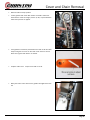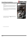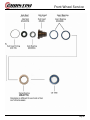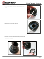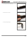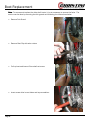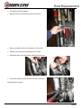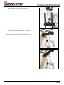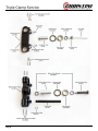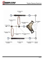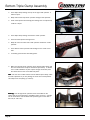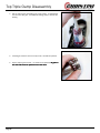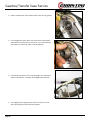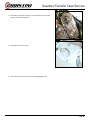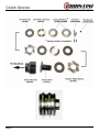
1
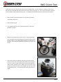
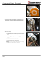
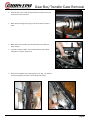
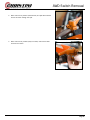
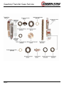
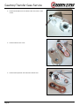
Service Manual
CHRISTINI AWD KTM
Christini Technologies, Inc.
[email protected]
Version 2011-1.0
Warnings:
•
Do not adjust the choke while the bike is moving!
Page 2
Page 3
Table of Contents
Table of Contents
Introduction; required tools
5
AWD detailed illustration
6
Routine maintenance schedule
7
AWD clutch test
8
AWD chain removal
9
AWD engagement adjustment
11
Front wheel removal
12
Front wheel service
14
Fork removal and installation
21
Dropout service
23
Fork spline bearing service
32
Boot Replacement
37
Triple clamp removal
39
Bottom triple clamp disassembly
41
Bottom taper bearing removal
48
Bottom triple clamp assembly
49
Top triple clamp disassembly
53
Top taper bearing removal
54
Top triple clamp assembly
55
Main drive shaft service
56
Headset bearing service
57
Gearbox removal
64
AWD cable removal
65
Gearbox/Transfer Case Service
67
AWD clutch Service
81
Troubleshooting
85
Warranty
86
Page 4
Required Tools
The Tools You Will Need for Maintenance
Page 5
•
Socket set, metric
•
Pliers set
•
Ball peen/ dead blow hammers
•
Soft tip metal punch (brass/aluminum)
•
Screw driver set
•
AWD clutch wrench (optional)
•
Open ended wrenches, metric
•
Allen key set, metric
•
Snap ring pliers, 45 or 90 degree
•
Bearing punch set
•
Blind side bearing removal kit (Motion Pro 08-0292)
•
2 large adjustable wrenches
•
Torque wrench 0-75 ft-lbs
•
Split bearing puller
•
Small pick or awe
•
Safety wire pliers
•
Safety wire .032”
•
Grease gun (included with frame kit. Fill with Shell grease)
•
Shell Albida EP1 Lithium grease (do not substitute)
•
Spectro SPL grease of equivalent
•
Blue Loctite #242
•
Red Loctite #262
•
Green Loctite #609
AWD Detail Illustration
Page 6
Routine Maintenance
Pre-ride check list:
•
Check secondary AWD chain tension.
•
Lube secondary AWD chain.
•
Check clutch setting with front wheel torque test (see next page).
•
Check front wheel rim lock nut torque.
As Needed
•
Replace bearings if excessive noise or friction develops.
•
Lubricate spline shafts through grease port with supplied grease
gun and Shell grease.
•
Replace worn or damaged seals and boots.
AVOID:
•
Page 7
Pressure washing the dropouts, head tube area, side bar
and main gearbox.
AWD Clutch Test
There are two ways to check that the clutch is set to the right torque. The first method is to take the clutch off the
bike and use the Christini AWD clutch tools and a torque wrench (see page 74). This is only recommended when the
clutch assembly is being rebuilt with new pads. The following test should be sufficient under most circumstances:
•
Place the bike on a stand and mak e sure that the front wheel is
not touching the ground.
•
Shift the bike into gear.
•
Turn the AWD switch to the on position and check to make sure
the AWD is engaged.
•
Grab the front wheel with two hands and try to spin it backwards.
The front wheel should spin backwards but require a larg e amount
of effort to do so. If the wheel will not break free, the clutch is set
too high. If the wheel turns backwards very easily, the clutch is set
too low.
•
If the clutch needs to be adjusted, pull the gas tank off the bike.
Loosen the set screw on the clutch locknut and turn the lock nut in
or out a 1/2 turn at a time until the front wheel moves backward
with the correct amount of force. Make sure the set screw is positioned over a flat in the clutch hub and tighten the set screw down
and reinstall the tank. (note: picture shows clutch off the bike for
clarity).
Page 8
Cover and Chain Removal
•
Remove the 4 cover bolts with an 8mm socket or t-handle and pull
cover off of the frame.
•
To remove the chain, pull the sprocket out with fingers or nonmarring pliers. Remove the chain from countershaft sprocket.
•
Check the following:
1. Sidebar bearing and cover bearing should be smooth turn
ing.
2. Check engagement spline action by engaging and disengaging switch on handle bars.
3. Sidebar seal and cover seal for wear.
4. Excessive wear on chain tension block.
Warning: Do not use an O-ring chain as there is not enough
clearance for one and it would rub the frame.
Page 9
Cover and Chain Removal
•
Reinstall chain and top sprocket.
•
Loosen gearbox with 4mm Allen wrench and slide it forward or
back until the chain has roug hly 40mm (1.5in) of space between
sides when pressure is applied.
•
If the gearbox is all the way forward and the chain is still too slack,
keep moving the set screw on the chain cover closer to the rub
block until a good chain tension is created.
•
Replace chain cover. Torque cover bolts to 8 ft-lb.
•
Move jack bolt in until it touc hes the gearbox and tighten the locknut.
Page 10
AWD Engagement Adjustment
•
Put motorcycle on a stand so both wheels are off the ground and
make sure the bike is in neutral.
•
Turn engagement switch back towards rider to the on position.
•
Spin rear wheel of motorcycle and make sure that the front wheel
is spinning as well (it may take a few turns before AWD clicks in).
•
Push engagement switch forward to the off position.
•
Spin rear wheel and make sure front wheel is no longer moving.
•
If the front wheel is still moving. Turn barrel adjuster on cable out
until the AWD system disengages and front wheel is no longer
moving.
Page 11
Front Wheel Removal
Note: Due to AWD hub design, front wheel removal and installation is
aided by removing front caliper first.
•
Remove front brak e caliper (note: do not squeeze front brake
lever while caliper is off.
•
Remove axle bolt from axle.
•
Loosen axle pinch bolts on both sides of dropout.
•
Slide axle throug h wheel and remove.
•
Remove front wheel from dropouts.
Note: The hub inserts will not fall out like the spacers on a normal hub.
They will also rotate independent of each other; this is ok.
Page 12
Front Wheel Installation
•
Lightly grease dropout o-rings and hub seals before installing the
front wheel.
•
With brak e caliper removed, install front wheel into forks by carefully aligning right drive carrier on dropouts with hub inserts. Once
the right carriers are seated, slide axle throug h to other end of
hub.
•
Carefully align lef t carriers and slide axle completely throug h to the
other side. Note, a flat blade screw may be needed to align hub
insert with drive carrier. Note that the hub inserts will only rotate
in one direction in the hub.
•
Thread axle bolt back into the end of axle and tighten to 12ft-lb.
Tighten axle pinch bolts to 12 ft-lb. Note: If wheel does not spin
freely, axle bolt is too tight!
•
Reinstall front brake caliper.
Page 13
Front Wheel Service
Page 14
Front Wheel Service
Warning: Before taking hub apart, make sure that you have a full set
of spare sprag bearings. Sprag bearings are likely to be damaged during the disassembly process and new onesmay be required.
•
Using a soft punch, remove the hub inserts from either side of the
hub.
•
Carefully remove all bearings, sprags and spacers from hub with a
punch and hammer. Be careful not to tap bearings out crooked as
it may damage hub shell.
Page 15
Front Wheel Service
•
Pry the insert seals out of the inserts using a flat bladed screwdriver.
•
Remove the hub insert o-rings with a pick.
•
Punch the axle bearings out of the inserts using the access holes
in the back of the inserts.
Page 16
Front Wheel Service
•
Using a bearing punch, install new axle bearings into the hub inserts.
•
Press the axle seals into the hub inserts.
•
Install the hub insert o-rings.
Page 17
Front Wheel Service
Warning: Sprag bearings must be installed in the correct orientation in the hub for the AWD system to work properly.
If the sprag bearings are not installed correctly, the AWD system can be damaged.
•
Press CB-6905 bearing into the Hub Inner Race
•
Be sure that the bearing is seated completely
•
Insert sprag bearing into hub shell. (correct direction will be determined in next steps.). Lightly grease inside of sprag bearing with
Shell grease.
Page 18
Front Wheel Service
•
Test fit hub insert into hub, twisting as it is inserted.
•
Spin the hub insert and check to make sure it is freewheeling in
the correct direction. If it is not, remove the hub insert and flip the
sprag bearing around. Recheck to verify that hub insert freewheels in the correct direction before moving on to next step.
Page 19
Front Wheel Service
•
Remove hub insert and press insert bearings into hub.
•
Grease hub insert seal, and slip hub insert into hub. It may be
required to tap hub insert into hub with a soft faced hammer.
•
Grease axle seal.
•
Repeat procedure for the other side of hub.
Page 20
Fork Removal
Warning: If removing forks for rebuild service, the fork dropouts must
be disassembled so that the drive system parts are not contaminated
during the service.
•
Loosen the housing cap from the linear bearing housing and unscrew it completely
•
Slide the housing down off the sprocket driveshaft
•
Looser top and bottom triple clamp bolts. Be sure to hold fork
while loosening bolts so it does not fall out. Slide fork out of triple
clamps and remove.
Warning —When fork is off the bike do not apply side pressure to spline
shafts as it is possible to bend them if enough force is applied.
Page 21
Fork Installation
•
Carefully slide forks into triple clamps.
•
If Honda 2004 or earlier forks are used, make sure they are at or
above the scribe line when inserted into the upper triple clamps.
Running the forks lower in the triple clamps may damage the linear spline bearings.
•
Set desired fork heig ht and torque triple clamp bolts to the following:
15 ft-lbs Lower
17ft-lbs Upper
•
Slide the linear bearing housing over the drive sprocket shaft
•
Tighten the housing cap down with 2 adjustable wrenches
•
Page 22
Dropout Disassembly
Page 23
Dropout Disassembly
•
Remove the front wheel and front fork.
•
Remove bellow clamp and bellow from spline driveshaft. Pry
gently with small flathead screw driver to undo clasp on clamp.
The clamps are not reusable!
•
Remove set screw from driveshaft with 2.5mm Allen key.
•
Remove driveshaft from pinion gear by lightly tapping lower
driveshaft with a plastic hammer while pulling the driveshaft
away from the dropout.
•
Remove 6 cover bolts on the outside of the gearbox using a
4mm Allen wrench.
• Rotate the cover and pull it off of the dropout.
Page 24
Dropout Disassembly
•
Remove drive insert bearing from inside of dropout. Bearing is a
slip fit so only light pressure from screw driver is required to
remove.
•
Tap down on pinion gear with plastic face hammer. After pinion is
removed, slide the bottom bearing out of dropout bore. If bearing
stays on pinion shaft, remove by hand or with split bearing puller.
Note: lower pinion bearing is angular contact so if pressure is
applied in the wrong direction it may come apart. If bearing comes
apart, it must be replaced.
•
Remove top driveshaft seal from dropout using small flat blade
screwdriver. Be careful not to scratch inner bore.
•
Remove top pinion bearings from upper bore by tapping them
lightly tapping from inside the dropout with non-marring punch.
•
Pry axle o-ring from dropout using small pick.
Page 25
Dropout Disassembly
•
Remove 4 drive carrier bolts with 4mm Allen wrench. The inner
hardened bevel gear can be clamped with soft jaws in a vise or the
drive carrier can be held with square bar stock to keep the
assembly from moving as you unscrew the bolts.
•
Lightly tap the outside face of drive carrier with plastic hammer to
break it free from gear and drive insert.
•
Remove axle o-ring from drive carrier with pick.
•
Remove cover o-rings and drive carrier o-ring.
Page 26
Dropout Disassembly
•
Remove cover bearing with bearing removal punch. Note o-ring lip
near inner race of bearing is easily damaged. Only apply pressure
to inner race of bearing.
•
Remove drive insert from gear with hammer and bearing removal
tool.
•
Before reassembly of dropouts, all parts must be cleaned and
inspected individually for damage or wear. Parts can be cleaned
with solution no different then OEM fork. Be sure to blow dry
dropouts and parts prior to reassembly if cleaning solution is used.
•
Pinion and bevel gear must be replaced as a set.
•
If bearings are seized or hard to turn by hand they must be
replaced or cleaned and repacked with grease.
•
Be sure to grease all o-rings and gears during reassembly.
Page 27
Dropout Assembly
•
Drive cover bearing into cover with bearing installation tools and
install inner and outer cover 0-rings. Note: all 0-rings should be
lightly coated with grease before being reassembled.
•
Insert drive carrier o-ring on drive carrier and insert drive carrier
into cover and tap into place. Note: face of drive carrier should be
flush with cover bearing and machined cover surface.
•
Place drive insert on tooth side of bevel gear and line up all four
threaded holes with clearance holes on gear.
•
Set cover and drive carrier on top of bevel gear assembly, with
smooth side of gear facing the cover. Line up 4 bolt holes and
thread drive carrier bolts into drive insert. Blue Loctite should be
used on bolts. Final tightening of bolts will require a square bar or
soft jaws to keep gear from spinning. Torque bolts to 8ft ft-lbs.
•
Check that bevel gear spins freely on cover. If it does not spin
freely, check to make sure all o-rings and the cover bearing are
properly seated. If new o-rings are used, there may be more
friction until o-rings seat and break in.
•
Insert axle o-ring into drive carrier.
Page 28
Dropout Assembly
Warning: Bevel gears are right and left hand specific and must be installed in the correct dropout or damage to the
system can occur. The Left Bevel Gear Set shown below must go in the disk side dropout. Note the difference in the
spiral direction on each gear set.
Note: Be sure dropout is clean before proceeding
•
Insert top pinion bearings and seal into driveshaft bore at top of
dropout using bearing driver. Note, be careful not to damage seal
or nick chrome fork plating with hammer. Use plastic faced
hammer.
•
Apply light grease to pinion seal
•
Insert bottom pinion bearing onto pinion gear.
WARNING: black seal must be facing down towards gear teeth. If
bearing is not inserted correctly, severe damage can occur!
•
Page 29
Slide bearing and pinion gear into bore. Make sure bearing is fully
seated.
Dropout Assembly
•
If needed use hammer and soft punch to tap end of pinion gear to
seat bearing.
•
Insert axle o-ring into dropout.
•
Install drive insert bearing and wedge small flat blade screwdriver
in between pinion gear and inner bearing to keep pinion gear in
place when the splined shaft is installed.
•
Slide splined driveshaf t onto pinion gear, making sure to line up
the set screw holes. Lightly tap end of spline shaft with plastic
faced hammer to slide it down onto pinion gear and line up set
screw holes.
Page 30
Dropout Assembly
•
Insert set screw with light dab of blue Loctite. When set screw is
fully seated, it will be slightly below the surface of driveshaft. If
not, make sure that spline shaft is fully seated on pinion gear.
•
Grease pinion gear and bevel gear with Shell Lithium grease.
•
Insert cover/bevel gear assembly onto dropout.
•
Insert 6 cover bolts and tighten in a cross star pattern using a
4mm Allen wrench. Tighten to 8ft-lbs.
•
Check that drive carrier spins freely and wipe excess grease from
outside of dropout.
•
Reinsert bellow and bellow clamp over spline shaft and crimp
bellow down using crimping tool or vise grips.
WARNING: The band of clamp must be over the set screw to ensure
that the set screw can not back out.
•
Lightly grease spline shaft with Shell Lithium grease.
•
Reinsert forks into triple clamps.
Page 31
Fork Spline Bearing Service
Page 32
Fork Spline Bearing Service
•
Cut Safety wire from boot and slide it off the housing.
•
Remove forks from triple clamps (see page 25).
•
Slide housing assembly off of linear driveshaft.
Page 33
Fork Spline Bearing Service
•
Unscrew grease port from linear bearing housing.
•
Slide housing sleeve off of housing.
•
Remove linear bearing retaining ring.
Page 34
Fork Spline Bearing Service
•
Slide linear bearing out of housing and inspect. If ball bearings
inside of the case are corroded or worn, replace linear bearing.
Warning: Do not use hammer and punch to remove bearing as it may
damage the bearing. If bearing will not slide out apply pressure to the
bearing lip with an 8mm nut driver to remove it.
•
If shaft seal is damaged or worn, pry it out and replace it with a
new seal.
•
Remove felt from housing sleeve and inspect. If needed, replace
felt.
Note: Dirt will pack up in felt. The felt can be cleaned and reused.
Page 35
Fork Spline Bearing Service
•
Saturate felt with gear oil and place it back in housing sleeve.
•
Reassembly of linear bearing housing is the reverse of
disassembly.
Warning: Use red Loctite on grease fitting or it may back out and cause
the housing sleeve to slide down while riding.
Warning: When sliding linear bearing housing back unto driveshaft,
carefully align the ball bearings with the grooves in the driveshaft. Do
not force the housing onto the driveshaft. Groove should be
approximately 90 degrees to the grease fitting.
Page 36
Boot Replacement
Note: To remove and replace the drive shaft boots, it is not necessary to remove the forks. The
service can be done by removing the fork guards and following the instructions below.
•
Remove Fork Guard
•
Remove Boot Clip with wire cutters
•
Pull up boot and loosen Drive shaft set screw
•
Insert screw drive in vent holes and tap screwdriver.
Page 37
Boot Replacement
•
The shaft will slide upwards
•
Remove Old boot and replace with a new boot.
•
Be sure to add the clip on the bottom of the shaft
•
Reinstall the drive shaft and tighten set screw
•
Slide boot back over the bottom shaft and set screw.
•
Crimp the clamp around the boot and set screw and
reinstall the fork guard
Page 38
Triple Clamp Removal
Note: To service the triple clamp chains, sprockets and bearings it is recommended that you leave the bottom triple
clamp attached to the bike. This will make it easier to pull the cover off. For servicing the steerer tube bearings, or
replacing the head tube gears, the triple clamps will need to be removed.
•
Remove forks and front fender from triple clamps.
•
Loosen the two preload bar pinch bolts.
•
Remove the preload bolts with a 22mm Wrench.
•
With a plastic faced hammer, tap the bottom triple clamp to
unseat it from the frame.
Page 39
Triple Clamp Removal
•
Slide the bottom triple clamp out of the frame.
•
Pull the top triple clamp assembly out of the frame.
Note: It may be necessary to tap the underside of the top triple clamp
with a plastic faced hammer to unseat it from the frame.
Page 40
Triple Clamp Service
Page 41
Triple Clamp Service
Page 42
Bottom Triple Clamp Disassembly
Note: To service the triple clamp chains, sprockets and bearings it is recommended that you leave the bottom triple
clamp attached to the bike. This will make it easier to pull the cover off. For servicing the steerer tube bearings, or
replacing the head tube gears, the triple clamps will need to be removed. For picture clarity, the triple clamp was removed from the bike.
•
Remove the forks and spline bearing assembly.
•
Remove the 4 cover bolts from the bottom of the triple clamp with
a 6mm Allen wrench.
•
Carefully pull on the shaft sprockets and ease the cover down from
the bottom triple clamp. The Left shaft will pull down with the
cover. The right shaft will stay in place and the cover will slide
down over it.
Page 43
Bottom Triple Clamp Disassembly
•
Remove the right shaft sprocket and the chain inside of triple
clamp cavity.
•
Pull center bottom sprocket off of the cover and remove the chain.
•
Pull both shaft sprockets out of cover. Be careful of seal as it
slides over snap ring grooves as it can tear the seal.
Page 44
Bottom Triple Clamp Disassembly
•
Remove cover bearings from cover with bearing puller if they need
to be replaced.
•
Remove cover seals and inspect. Replace if needed.
Page 45
Bottom Triple Clamp Disassembly
•
Remove sprocket snap ring .
•
Remove sprocket and gear by tapping the gear through the
sprocket with a plastic faced hammer and pulling it out the top of
the steerer tube.
•
Remove gear from steerer tube. If bearing comes out with gear,
remove bearing from gear with split bearing puller if it does not
slide off easily.
•
If top bearing remains in steerer use a punch to remove it.
Page 46
Bottom Triple Clamp Disassembly
•
Tap the bottom output bearing from the bottom steerer tube.
•
Inspect gears and bearing and replace any parts if needed.
Note: Head tube gears must be replaced in sets.
Page 47
Bottom Taper Bearing Removal
Warning: Replacing the taper bearing is a job for your dealer. Do not
attempt to do this on your own.
•
Remove the preload bars from the bottom triple clamp.
•
Press the steerer tube out of the bottom triple clamp with an arbor
or hydraulic press. The steering stops should be supporting the
triple clamp as the steerer is pressed out.
•
Press the taper bearing and seal off of steerer tube with an
aluminum sleeve available from Christini.
•
Press new taper bearing and seal onto steerer tube.
•
Coat mating surface of triple clamp and steerer tube with green
Loctite.
•
Press steer tube into triple clamp.
Page 48
Bottom Triple Clamp Assembly
•
Press steerer bearing into the top of the steerer tube.
•
Press steerer bearing into bottom of the steerer tube.
•
Install bottom output gear and tap sprocket back onto bottom of
gear using a plastic faced hammer. Sprocket is fully seated when
the end of it is flush with the snap ring groove.
•
Replace snap ring.
Page 49
Bottom Triple Clamp Assembly
•
Install cover seals.
•
Press cover bearings back into outer bores of cover.
•
Insert Teflon chain guides into cover if they were removed. Note
the wear pattern and be sure that the guides are placed on the
same side as they were removed from.
Page 50
Bottom Triple Clamp Assembly
•
Insert triple clamp bearing onto top of the right shaft sprocket. It
will be a slip fit.
•
Wrap chain around top center sprocket and rig ht shaft sprocket.
•
insert shaft sprocket and bearing into bearing bore on triple clamp.
It will be a slip fit.
•
Insert triple clamp bearing onto bottom center sprocket.
•
Push left shaft sprocket through cover.
•
Wrap the chain around the left shaft sprocket and bottom center
sprocket.
•
Insert bottom center sprocket with bearing into the center cover
hole.
•
If needed, grease chains with Shell grease.
•
Slide cover and left shaft sprocket up into bottom triple clamp until
the cover meets flush the lip of the bottom triple clamp. If needed
use a small screwdriver or pick to push the right chain away from
the Teflon block as the cover slides into place.
Hint: once the cover makes contact with the bottom triple clamp, rotate
the shaft sprockets as you are pushing the cover into its final position.
This helps to line everything up correctly.
Warning: Left and right shaft sprockets must be installed on the
correct side or severe damage to the AWD system can occur. A simple
rule to remember is that the lower shaft sprocket goes on the rider’s
left side (ie: Left=Low).
Page 51
Bottom Triple Clamp Assembly
•
When cover is in place screw down the cover bolts with a 6mm
Allen wrench.
Note: Use blue Loctite on cover bolts. Torque bolts to 12 ft-lbs
Page 52
Top Triple Clamp Disassembly
•
Pull top output gear and bearing out of top steerer. If bearing does
not come out with gear, use blindside bearing puller to remove the
bearing
•
If bearing is seized or hard to turn by hand, it should be replaced.
•
Inspect output gear for wear. If it needs to be replaced, all gears in
the head tube must be replaced at the same time.
Page 53
Top Taper Bearing Removal
Warning: Replacing the taper bearing is a job for your dealer. Do not
attempt to do this on your own.
•
Loosen steerer set screw in triple clamp and remove the steerer
tube.
•
Press taper bearing and seal off of steerer tube with an arbor or
hydraulic press.
Note: A new seal will be needed as it will be damaged when the taper
bearing is pressed off the steerer.
•
Press new taper bearing and seal onto steerer tube.
•
Insert steerer tube into top triple clamp and tighten set screw to
secure steerer tube.
Page 54
Top Triple Clamp Assembly
•
Slide the steerer tube bearing back onto the output gear.
•
Press gear and bearing into top steerer tube.
Page 55
Main Drive Shaft Service
•
Remove the head tube cover from the front of the head tube.
•
Slide the input head tube gear and main driveshaft out the head
tube access port. The driveshaft will need to slide out of the clutch
hub. Be careful not to loose the key when separating the
driveshaft from the clutch hub (not all models have key).
•
If the 3 input bearings do not come out with the input gear, gently
tap them out with a punch. Make sure they do not get cocked as
they are being tapped out.
Warning: If any of the head tube gears are damaged and need to be
replaced, all of the head tube gears must be replaced together as a
set.
Page 56
Headset Bearing Service
*
*
Picture above shows a head tube not
welded to the frame for reference.
Page 57
Headset Bearing Service
•
Use a punch and remove the inner B543 bearings.
•
If the taper bearing races are corroded or pitted, remove them with
a punch.
•
Clean the headset bearing surfaces with degreaser and apply a
few drops of green Loctite.
•
Install the inner B543 bearings using a bearing punch.
•
Install the taper bearing races using a bearing punch.
Page 58
Main Drive Shaft Service
•
Slide the input bearings onto the head tube gear.
•
Slide the driveshaft the rest of the way through the frame, seating
the input bearings and gear in the head tube and the clutch hub
with the clutch basket. Use a soft punch and lightly tap the gear to
be sure it is fully seated.
Page 59
Triple Clamp Installation
•
Grease the top and bottom taper bearings and output gears with
Shell grease.
•
Check to make sure input head tube gear and bearings are
completely seated in the back of the head tube.
•
Slide top triple clamp assembly into the head tube.
•
Before seating the top triple clamp assembly, make sure the
output gear and input gear are beginning to mesh correctly.
Note: If the two gears are not meshing, it will not be possible to seat
the top triple clamp correctly.
•
Tap the top triple clamp with a plastic faced hammer to seat it
completely.
Page 60
Triple Clamp Installation
Slide the bottom triple clamp partway into the head tube as you do the
following:
•
Align the preload bars so they begin to slide into the top triple
clamp.
•
Make sure the bottom output gear and input gear are meshing
correctly.
Page 61
Triple Clamp Installation
•
Finally, spin the left side sprocket driveshaft to alig n the bottom
center sprocket (located inside the cavity) with the steerer
driveshaft. Once turning the sprocket driveshaft also turns the top
output gear, everything is aligned correctly.
•
Tap the bottom triple clamp with a plastic faced hammer to
completely seat it in the frame.
•
Screw the preload bolts down until they are flush with the top triple
clamp.
Page 62
Triple Clamp Installation
•
Turn the preload bolts evenly until there is no play in the headset
(usually 1/2-3/4 of a turn).
•
Tighten the preload bar pinch bolts.
Page 63
Gear Box/Transfer Case Removal
•
Remove chain cover, chain and sprocket from transfer case (see
chain cover removal section).
•
Slide clutch retaining snap ring up main drive shaft 6 inches or
more.
•
Slide clutch hub assembly up main driveshaft unit it clears the
clutch basket.
•
If present (certain models), remove driveshaft key with needle
nose pliers so it does not get lost!
•
Remove all 6 gearbox bolts retaining bolts (4 on top, 2 on bottom)
and remove gearbox/transfer case assembly from frame.
Page 64
AWD Switch Removal
Switch Shown in off position
Page 65
AWD Switch Removal
•
Move switch to on position (towards rider) and pull cable forward
and out of switch through the split.
•
Move switch to off position (away from rider) and remove cable
end from the switch.
Page 66
Gearbox/Transfer Case Service
Page 67
Gearbox/Transfer Case Service
Page 68
Gearbox/Transfer Case Service
•
Remove 6 M6 bolts from the transfer case cover with a 8mm
socket.
•
Remove transfer case cover.
•
Remove both sprockets and chain from transfer case
Page 69
Gearbox/Transfer Case Service
•
Remove the 4 shoulder bolts from the transfer case with a 4mm
allen wrench.
•
Separate the transfer case from the gearbox.
Page 70
Gearbox/Transfer Case Service
•
Remove O-ring from the back of the transfer case if it is damaged.
•
If the transfer case bearings need to be replaced, remove them by
tapping the bearings out with a socket or punch.
Page 71
Gearbox/Transfer Case Service
•
Remove the transfer case cover seal.
•
Remove the 6905 transfer case cover bearing with a socket or
punch.
•
Remove the 6804 transfer case cover bearing with fingers. It is a
slip fit in the bore so it should come out easily.
Page 72
Gearbox/Transfer Case Service
•
With the engag ement cable remove from the switch, pull the spline
out from the gearbox and remove the cable fitting from the spline
using a small flat blade screw driver.
•
With cable fitting removed. Pull spline and spring out of input gear
and pull the cable out the back of the gearbox.
Page 73
Gearbox/Transfer Case Service
•
Slide clutch basket off output gear.
•
Remove output seals from gear box.
•
Remove output snap ring.
Page 74
Gearbox/Transfer Case Service
•
Slide output gear and bearings out of gearbox.
•
Remove input gear and bearing from gearbox by tapping them out
throug h the access holes in the back of the gearbox.
Page 75
Gearbox/Transfer Case Service
•
Remove output retaining ring.
•
Use split bearing puller to press output bearings partially off of the
gear. After the bearings move away from the gear, use press to
remove bearings completely.
•
Use same steps to remove input bearing from input gear.
•
Inspect gears and bearings and replace if needed.
Page 76
Gearbox/Transfer Case Service
•
Reassemble gearbox in the order in which is was disassembled.
•
Grease gearbox gears.
•
Be sure that the spring retaining post is facing up inside the input
gear spline, and is positioned on the middle ledge inside the
spline.
•
Grease engag ement spring and spline with Shell grease and
reinstall with cable and fitting inside the gearbox.
Page 77
Gearbox/Transfer Case Service
•
Remount gearbox on the frame, with transfer case still removed.
Make sure engagement spline/cable assembly does not fall out of
gearbox.
•
Press engagement spline all the way into gearbox to take up spare
cable slack.
•
Reinstall cable into the engagement switch. Test switch and make
sure it is moving the engagement spline in and out of gearbox.
Page 78
Gearbox/Transfer Case Service
•
Grease shoulder bolts and reinstall transfer case onto the gearbox.
•
Push engagement switch all the way forward and install gearbox
driveshaft and sprocket into top of transfer case. Spin driveshaft
and sprocket to make sure spline is fully disengag ed.
•
If driveshaft and sprocket do not full disengage, turn cable barrel
adjuster until spline is completely disenagaged from driveshaft.
•
Test engagement by flipping switch back and forth a few times
while spinning gearbox driveshaft and sprocket.
Page 79
Gearbox/Transfer Case Service
•
Reinstall top and bottom transfer case sprockets and chain and
grease chain with Shell grease.
•
Reinstall transfer case cover.
•
See chain cover removal section for reinstalling AWD chain.
Page 80
Clutch Service
Page 81
Clutch Service
•
Remove the clutch from the main driveshaft, by first removing the
gearbox and then sliding the clutch off the main driveshaft.
•
Loosen locknut set screw so it will not interfere with the hub
threads.
Warning: Failure to remove set screw will damage threads in clutch
hub.
•
Remove locknut from clutch hub.
•
Remove spring washers, fiber pads and clutch plates and inspect
for wear or damage.
Note: If metal plates are not scored or warped, they do not need to be
replaced. Simply replace fiber plates during standard rebuilt.
Page 82
Clutch Service
•
Reassemble clutch hub noting the order of the plates, fibers and
spring washers. Be sure the spring washers are in the correct
orientation:
))
•
Use thread file to clean galled hub threads if needed
•
Apply anti seize compound to hub thread and thread locknut onto
the hub. Tighten until locknut is approximately flush with the hub.
Page 83
Clutch Service
•
Reinstall clutch on bike.
•
To check clutch settings and adjust as necessary, see
section “AWD Clutch Test”
•
Adjust locknut so set screw hole lines up with the nearest flat section on the hub, and tighten set screw.
Warning: Once set screw is tightened, do try to turn locknut as this will damage the hub threads
Page 84
AWD Troubleshooting
Problem
Solution
•
Clean and lube fork seals.
•
Check to make sure forks are not twisted in triple
clamps.
•
Lube front spline shafts with grease.
•
If this does not help, pull down dust boot and check
spline shaft for damage.
•
Disassemble spline and check bearing for corrosion and
damage.
•
Make sure engagement switch is turned on and the engagement spline is functioning properly.
•
Check clutch setting for proper torque using “wheel
check method”.
•
Check sprag bearings in hub to make sure neither side is
slipping.
•
Make sure that drive shafts are free to spin smoothly.
Occasionally mud or other debris can hinder one driveshaft from spinning at the proper rate.
Clutch Basket has notches in it.
•
This is normal. As long as the notches don’t exceed
3/16”, Replacement is not needed.
Cannot disengage system
•
With bike in neutral rock it back and forth and use the
lever to disengage the system.
•
Engagement cable has too much slack in it. Use barrel
adjuster to take slack out of cable.
Front forks feel sticky
Front wheel is not pulling
Drive system is pulling to one side
Page 85
Warranty
CHRISTINI AWD LI MITED WARRANTY
This LIMITED WARRANTY is a complete and ex clusive statement of CHRISTINI’s obligations to the
ORIGINAL OWNER of a CHRISTINI AWD Motorcycle Kit.
CHRISTINI Technologies warrants:
-All Modified frames to be free from defects in material and workmanship for a period of ONE (1) year from the date of
purchas e fo r the Original Owner.
-All other original CHRISTINI AWD components, including the fork machined parts, front hub, gear box, and the components of the CHRISTINI All Wheel Drive (AWD) system including shafts and drive gears are warranted to be free o f defects in material and workmanship for a period of ONE (1) year from the date o f Purchase for the Original Owner.
OTHER ORIGINAL COMPONENTS
Any components not produced by CHRISTINI, including the front suspension fork intern al mechanisms, bear their original
manu factu rer’s own warranty and CHRISTINI reserv es the right to direct any warranty requ est relating to those Other
Original Components to said manufacturer’s customer service dep artment.
THESE WARRANTIES DO NOT COVER:
•
•
•
•
•
•
•
•
•
•
•
•
•
•
•
•
•
•
•
•
•
•
Failures or required services which are not due to a defect in material or factory workmanship.
Replacement o f expend able maintenan ce items including, but not limited to:
Bearings, including linear bearing
Seals and O-Rings
AWD Clutch Basket, Plates, and Friction Plates
Shaft Bellows
AWD Engagement cable and housing
Sprockets and Drive Chains
Parts or accessories affected or damaged by:
Normal wear
Finish, including frame, anodized machine parts, and coatings on gears, sprockets and driveshafts
Improper maintenan ce including improper clutch settings
Lack o f proper mainten ance
Improper installation
Deterioration from exposure to the elements
The unauthorized alteration of any part
The incorporation or use of unsuitable attachments or parts
Unsuitable use in an application for which the part was not designed
Neglect
Misuse
Abuse
Vandalism
Failures caused by or related to any modification not approved by Christini Technologies, Inc.
Page 86
Warranty
•
Failures caused by or related to any installation of any parts or kits designed for “competition only” use
•
Use for the following activities: which will VOID these warranties:
• Racing
• Competition
• Rental
LIMITED REMEDY
Unless otherwise provided, the sole remedy under the above warranty or any implied warranty is limited to the replacement
of defective parts with those of equal or greater valu e at the sole discretion of CHRISTINI. No cash refunds will be offered
under this warranty and you will be responsible for labor costs associated with warranty replacements. IN NO EVENT
WILL CHRISTINI AWD BE RESPONSIBLE FOR INCIDENTAL OR CONSEQUENTIAL DAMAGES, WHETHER
BASED ON CONTRACT, WARRANTY, NEGLIGENCE, OR STRICT PRODUCTS LIABILITY, INCLUDING, WITHOUT LIMITATION, PERSONAL INJURY DAMAGES, PROPERTY DAMAGE, OR ECONOMIC LOSSES.
Note: In those states that do not allow the exclusion or limitation of incidental or consequential damages, the above limitation or exclusion may not apply to you.
EXCLUSIONS
The above warranty, or any implied warranty, does not cover normal WEAR AND TEAR, and all warranties are void if
the motorcycle is used for other than normal activities, including, but not limited to, the failure to follow the directions
for assembly, the instructions, warnings and advice found in the owner's manual or using the motorcycle for commercial activities or in competitive events, including off road racing, motocross racing, stunt riding, ramp jumping or similar activities and training for such activities, or events. This warranty does not cover any damage, failure, or loss
caused by accident, misuse, abuse, neglect, improper assembly, improper maintenance, or use of parts or devices not
consistent with the original intent for the product sold.
CHRISTINI TECHNOLOGIES MAKES NO OTHER WARRANTIES, EITHER EXPRESSED OR IMPLIED. ALL IMPLIED WARRANTIES, INCLUDING THE WARRANTIES OF MERCHANTABILITY AND FITNESS FOR A PARTICULAR PURPOSE, ARE LIMITED, IN DURATION TO THAT OF THE EXPRESS WARRANTIES STATED
ABOVE. Some states do not allow limitations on how long an implied warranty lasts so the above limitation may not apply
to you. The warranty gives you specific legal rights, and you may also have other rights, which vary from state to state.
WHAT YOU SHOULD DO
Always wear a helmet while riding. Please remember to always ride safely and in control and within your capabilities
and limitations. Even under normal riding, motorcycles can be dangerous due to changing and variable riding conditions including know n and unk nown hazards.
WARRANTY CLAIM PROCEDURE
•
If a part is determined to be defective, return said part to your dealership for verification of a defect.
•
The dealer will verify whether the part is defective. If the part is determined to be defective by the dealer, the part
will be replaced and the amount of the replacement part will be charged to the customers credit card until it is returned to Christini for verification.
•
Alternatively, the dealer may opt to send the part in for verification bef ore replacement.
•
Upon receipt of the defective part/parts, Christini will determine if the part is eligible for warranty compensation.
If the part is found to be defective, the customer will be credited the full amount of the replacement part.
This Warranty applies only to the Original Owner (first retail purchaser from motorcycle dealer, distributor, or direct
from Christini)
Page 87
Warranty
Bring your AWD kit along with your purchase receipt or other proof of the date of purchase to the dealer where you
purchased the AWD Kit or write to the Warranty Service Department at:
CHRISTINI AWD
421 N. 7th Street, Suite 200
Philadelphia, PA 19123
Phone: (215) 351 9895
Freight costs and any labor charges for part change overs, assembly, repair, or disassembly are the responsibility of
the Original Owner and this Warranty offers no cash refunds.
Page 88
Notes: