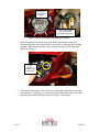
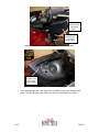
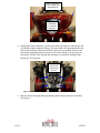
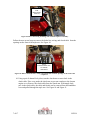
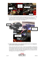
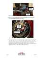
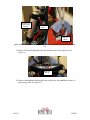
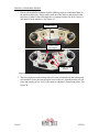
1
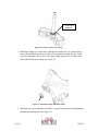
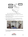
INSTALLATION INSTRUCTIONS FOR THE MOTOR TRIKE CROSS COUNTRY / CROSS ROADS / HARD BALL RAKE KIT Thank you for choosing the Motor Trike Cross Country / Cross Roads / Hard Ball rake kit. We ask that you read the directions before you start and follow them very closely. Doing so will save you time and ensure that the customer’s experience with their new rake kit is a positive one. It is critical that proper eye wear, ear protection, and protective clothing is worn throughout this rake kit installation. Failure to secure this vehicle during installation could result in injury up to and including death. If you do not have the proper tools to do this installation, DO NOT ATTEMPT TO PERFORM THE INSTALLATION. When placing your order, please remember to provide the bike year and model. This information is necessary for you to receive the correct parts. (Ex. 2012 VICTORY CROSS ROADS) When you receive your kit, please check to ensure that all parts and hardware are included and/or assembled correctly. Use the supplied assembly drawing as an aid. If there are any parts missing or if you have any questions concerning the kit at this time call Motor Trike at 1-800-90TRIKE (800-908-7453) Mon-Fri 8am-5pm CST. Or you can email us at [email protected] The installation process may vary for different years and/or models. Motor Trike Inc. reserves the right to change specifications, equipment, or designs at any time without notice and without incurring obligation. 2 of 17 REV B DISASSEMBLY PROCEDURE Note: These instructions are written for the Cross Country / Cross Country Tour models. Some steps may not apply or may vary for other models. 1. Support the motorcycle across the bottom of the frame with a block of wood, and lift behind the front tire until the tire is off the ground. See Figure 1 below. SUPPORT HERE Figure 1: Support the front of the motorcycle and lift the front tire. 2. Cover the fuel tank and the front fender with a soft clean towel to protect the paint through the remainder of the procedure. 3. The front headlight bezel is snapped in place (no screws) and can be removed by hand (no tools needed). Pull the bezel forward to remove it. Be careful not to scratch the paint. See Figure 2. PULL FORWARD AT ARROWS Figure 2: Pull the bezel off the front headlight. 4. Remove the screws that hold the headlight in place. Pull out the headlight and unplug the connectors from the back of each bulb. Note which connector goes on the top and bottom bulb. See Figure 3. 3 of 17 REV B REMOVE 4 HEADLIGHT SCREWS UNPLUG THE HIGH AND LOW BEAM HEADLIGHT BULBS Figure 3: Remove the headlight and unplug the connectors. 5. The turn signals are mounted to the outer shell of the fairing, and must be disconnected before removing the shell. Locate the wires through the headlight opening. Unplug both connectors. One for the left and one for the right turn signal. See Figure 4. TURN SIGNAL CONNECTER AND WIRE Figure 4: Unplug the turn signal wires. 6. The front fairing consists of two shells screwed together and bolted to the triple tree assembly. Carefully pry out the speaker grills, then remove the screws that attach the outer shell to the inner shell. See Figure 5 and Figure 6. 4 of 17 REV B PRY HERE TO REMOVE THE SPEAKER GRILL REMOVE SCREWS (ON LEFT AND RIGHT SIDE) Figure 5: Remove the screws holding the outer shell to the inner shell. REMOVE SCREW (ON LEFT AND RIGHT SIDE) Figure 6: Remove the screw under the speaker grill. 7. Place masking tape under the edge of the windshield to prevent damage to the paint. Carefully pull the outer shell away from the inner shell. See Figure 7. 5 of 17 REV B APPLY MASKING TAPE UNDER THE WINDSHIELD PULL SHELL FORWARD AT DASHED ARROWS Figure 7: Remove the outer shell of the fairing. 8. Unplug all wiring connectors, cut all of the strain relief zip ties, and unscrew the wire bundle clamps inside the fairing. The inner shell will remain attached to the framework inside the fairing and will be removed as an assembly. Remove the four fairing mounting bolts to remove the rest of the fairing. You may need an assistant to feed the wires through the openings as you pull the fairing off the motorcycle. See Figure 8. REMOVE THE FOUR MOUNTING BOLTS Figure 8: Remove the fairing after you disconnect all electrical connections. 9. Remove the left and right fairing mounting struts from the triple tree assembly. See Figure 9. 6 of 17 REV B REMOVE THE MOUNTING STRUTS Figure 9: Remove the fairing mounting strut from the triple tree assembly. Follow the next several steps to remove the brake line, wiring, and clutch cable from the openings on the front of the triple tree. See Figure 10. PULL EVERYTHING OUT OF THESE OPENINGS Figure 10: Remove the brake line, wiring, and clutch cable from the openings on the front of the triple tree. 10. Using a pair of channel lock pliers, turn the clutch arm to create slack in the clutch cable. Place a rag under the clutch arm to prevent scratches to the chrome engine cover. Remove the clutch cable from the clutch arm. With ample slack now in the clutch cable, the cable and ferrule can be removed from the handlebar lever and pulled through the triple tree. See Figure 10 and Figure 11. 7 of 17 REV B CLUTCH CABLE TURN THE CLUTCH ARM WITH PLIERS CLUTCH CABLE FERRULE Figure 11: Remove the clutch cable from the clutch arm and the handlebar. 11. To remove the throttle cables from the twist grip, first remove the screws and the cover, then pull the cables from their mounts. With slack in the cables, the ferrules can now be removed from the twist grip. Finally pull the throttle cables through the triple tree. See Figure 10 and Figure 12. REMOVE SCREWS PULL CABLE OUT OF POSITION REMOVE THE FERRULES FROM THE GRIP Figure 12: Remove the throttle cables from the twist grip. 12. Caution: Brake fluid corrosive and ruins paint. Be sure to cover all painted surfaces before removing the brake line. Unscrew the banjo bolt from the master cylinder on the handlebars. Pull the brake line through the opening on the triple tree, then reinstall the banjo bolt and tighten to prevent leaks. Be sure to keep track of the sealing washers. There is one on the top and bottom of the brake line fitting. Immediately wipe up any drips and wash with soapy water. See Figure 10 and Figure 13. 8 of 17 REV B SEALING WASHERS BANJO BOLT Figure 13: Remove the brake line and reinstall after pulling it through the triple tree. 13. Remove the brake calipers and the wheel speed sensor from the down tubes. Leave the brake lines attached to the caliper. BRAKE CALIPER BOLTS WHEEL SPEED SENSOR BOLT Figure 14: Remove the brake calipers and wheel speed sensor from the down tube. 14. Loosen the down tube clamp bolts in the upper and lower triple tree on both sides of the bike. Raise the motorcycle chassis and slide the front wheel / down tube assembly out of the triple trees. Once removed from the bike, the front wheel can be rolled to a separate front wheel vise and clamped in place. Use a zip tie through the brake caliper bolt and through one of the brake rotor retaining pins to keep the down tubes / fender from rotating. See Figure 15. 9 of 17 REV B RAISE LIFT AND SLIDE DOWN LOOSEN BOLTS ZIP TIE HERE Figure 15: Remove the front wheel / down tube assembly from the triple trees and store it in a tire vise. 15. Remove the bolts holding the brake line bracket to the lower triple tree. See Figure 16. REMOVE BOLTS Figure 16: Remove bolts from the brake line bracket. 16. Remove the handlebar bushing bolts and carefully lay the handlebars on top of a protected gas tank. See Figure 17. 10 of 17 REV B REMOVE BOLTS Figure 17: Remove the handle bar bushing bolts and lay the handlebars on a protected gas tank. 17. Remove the retaining nut on the upper triple tree, then remove the upper triple tree and steering stem spacer. Remove the adjustment nut from under the upper triple tree and slide the lower tree and stem out the bottom. The adjustment nut is a spanner wrench style nut, but should have very little torque on it. You should be able to remove it with a screw driver and a tap from a hammer if you do not have the proper wrench. See Figure 18. UPPER TREE RETAINING NUT LOWER TREE ADJUSTMENT NUT Figure 18: Remove the triple trees. 18. Drive out the lower bearing race from the frame. Use a long drift and a hammer. Work your way around the race to drive out the race evenly. The upper bearing will be reused and can remain in the frame. 11 of 17 REV B INSTALLATION PROCEDURE 1. Remove the handlebar bushings from the OEM top triple tree and install them in the raked top triple tree. These can be pried out of the old tree and pressed in the raked tree by hand. If the OEM triple tree is equipped with a fork lock, remove it and install it in the raked tree. See Figure 19. FORK LOCK HANDLE BAR BUSHINGS FORK LOCK BOLTS Figure 19: Install the bushing in the raked top tree and install the fork lock if equipped. 2. The lower triple tree and steering stem will come assembled with the bearing and seal installed. Grease the bearing on the lower triple tree. Spin the bearing several times and reapply grease. Every roller must be completely coated with grease. See Figure 20. 12 of 17 REV B LOWER TREE BEARING Figure 20: Grease the lower tree bearing. 3. Install the bearing race in the frame with the cone facing out. Use a brass drift or other soft material to tap the race in place. Do not dent or scratch the race. Work your way around the race to drive it in evenly. Make sure the race is fully seated in the frame before proceeding. See Figure 21. Figure 21: Install the bearing race in the frame. 4. Install the lower tree assembly on the bike. Loosely thread the steering adjustment nut onto the steering stem. See Figure 22. 13 of 17 REV B ADJUSTMENT NUT UPPER TREE BEARING (STILL IN FRAME) UPPER TREE SEAL Figure 22: Install the lower tree assembly. 5. Torque the bearing adjustment nut using the following procedure. Turn the lower tree all the way to the right and torque the adjuster nut to 29 ft*lbs. Turn the lower tree all the way left and back right five times. Turn the lower tree all the way left, and mark one of the slots on the adjustment nut with a piece of tape on the frame. Loosen the adjuster nut 90 degrees. A new slot on the nut should now be aligned with the tape. This completes the procedure for tightening the bearing adjuster nut. 6. Install the top triple tree clamp, retaining nut, and spacer. Do not torque the retaining nut at this time. See Figure 23. 14 of 17 REV B RETAINING NUT OEM SPACER TOP TRIPLE TREE CLAMP Figure 23: Install the top triple tree clamp, retaining nut, and spacer. 7. Reinstall the brake line bracket on the lower tree. Apply blue Loctite 242 and torque to 10 ft*lbs. See Figure 16. 8. Reinstall the handlebars to the upper tree. Apply blue Loctite 242 and torque the bolts to 40 ft*lbs. See Figure 17. 9. Unscrew each fork cap from the down tubes. The damping rod will still be attached to the fork cap when you remove it. Slide the down tube toward the wheel to gain further access. See Figure 24. FORK CAP Figure 24: Unscrew the fork caps. 10. To release the fork cap from the damping rod, the spring must be compressed. Victory sells a down tube spring compressor that we recommend you use for this process. See Figure 25. 15 of 17 REV B DAMPING ROD JAM NUT COMPRESS THE SPRING Figure 25: Compress the spring to access the damping rod jam nut. 11. Hold the jam nut stationary, and turn the fork cap to remove it from the damping rod. 12. Remove the o-ring from the OEM fork cap and reinstall it on the fork cap extension supplied with the rake kit. Inspect the o-ring for damage and replace it if necessary. See Figure 26. EXTENDED FORK CAP MOVE O-RING HERE OEM FORK CAP Figure 26: Swap the o-ring from the OEM cap to the extended cap. 13. Install the new fork cap on the damping rod. Bottom out the cap on the damping rod before tightening the jam nut. Hold the jam nut and torque the extended fork cap to 9.5 to 12 ft*lbs. Carefully release the tension on the spring, and make sure the spring is properly seated against the cap. Lift the down tube up to the cap, then tighten the cap to the down tube at 18 ft*lbs. 14. Slide the down tube / wheel assembly into the triple trees. The top of each fork extension should be even with the top of the upper triple tree. Apply blue Loctite 242 and tighten the clamp bolts on the bottom tree to 17 ft*lbs. 15. Torque the retaining nut on the upper triple tree to 72 ft*lbs. See Figure 23. 16. Torque the clamp bolts on the top tree to 17ft*lbs. 17. Reinstall the brake calipers and front wheel speed sensor. Apply blue Loctite 242 and torque the caliper bolts to 31 ft*lbs. Apply blue Loctite 242 and torque the front wheel speed sensor to 8 ft*lbs. See Figure 14. 16 of 17 REV B 18. Run the brake lines, clutch cable, throttle cable and wiring back through openings on the top triple tree and reinstall all parts in their original locations. See Figure 10, Figure 11, and Figure 12. 19. Install the fairing mounting struts. Apply blue Loctite 242 and torque the bolts to 19 ft*lbs. See Figure 9. 20. Install the back shell of the fairing and fairing mounting bracket as an assembly. Apply blue Loctite 242 and torque the bolts to 19 ft*lbs. See Figure 8. 21. Plug in all connections and reattach any wire strain relief that you removed during disassembly. 22. Install the outer fairing shell. See Figure 5, Figure 6, and Figure 7. 23. Plug in the headlight and have an assistant hold it in place. Test all of the buttons on the instrument cluster and handlebars for proper function. Make sure that the radio, ignition, grip heaters, turn signals, cruise control, high beam, and low beam all work before installing the headlight. Any missed connections can be fixed through the headlight opening. Slowly turn the handle bars all the way left and all the way right while inspecting for clearance. Make sure there are not any wires being pinched around the triple trees. Make sure the handlebars and fairing do not collide with the gas tank. 24. Install the headlight and torque the headlight bolts to 7 ft*lbs. Re-aim the headlight according to the Victory factory service manual instructions. Snap the headlight bezel in place. See Figure 2 and Figure 3. 25. Bleed the front brakes according to the Victory factory service manual. Be sure to leave all painted surfaces covered to prevent damage from brake fluid. Be sure to add fluid to the reservoir as you bleed the brakes. 26. Test drive the bike first at parking lot speeds. Feel for any looseness in the steering when using the front brakes. Make sure the steering effort is not being affected by over tightened steering bearings. Once the bike has been thoroughly checked in the parking lot, take it for a test drive on the highway. If you have any questions or concerns about the installation, please call Motor Trike at 1-800-90-TRIKE. Otherwise, wipe down the motorcycle, return it to your customer, and tell them to enjoy the ride. Thank you for choosing the Motor Trike rake kit for your Victory motorcycle. 17 of 17 REV B