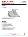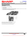
1
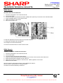
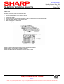
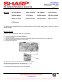
CTV990504
Month of Issue: May 1999
Classification:
White
Page 1 of 7
TELEVISION TECHNICAL BULLETIN
MODELS
BCTVA Chassis
4BS-C Chassis
CA1 Chassis
CA10 Chassis
CW100 Chassis
CS Chassis
D3000 Chassis
DECO-4 Chassis
DECO-5 Chassis
4BS-B Chassis
4BS-A Chassis
5BS- A Chassis
S3B Chassis
To assist with the adjustments of the above chassis, the list below details how to enter the various
service modes.
BCTVA Chassis
66AS06H, DV5932H, DV5935H, DV5937H and DV6635H
1.
2.
3.
4.
5.
Connect a test pattern to the antenna terminal
Tune to this signal
Connect a jumper wire between terminals 2 (GND) and 6 (Service) of the service slot on the Video Unit
SERVICE SOFTWARE will appear on the screen
Remove the jumper wire
Use the channel up and down buttons to move between the options
Use the volume control buttons to change the data
Use the standby button on the remote control to store the data
Turn the receiver off at the mains to exit the service mode
Sharp Electronics (UK) Limited
Reference AVW060599/1
Revision 1
White – Carry out as required, Yellow – Carry out as required and whenever the unit comes in for service, Red – Carry out on all units
CTV990504
TELEVISION TECHNICAL BULLETIN
Month of Issue: May 1999
Classification:
White
Page 2 of 7
4BS-C Chassis
DV5940H, DV6640H and 66AS05H
1.
2.
3.
4.
5.
Connect a test pattern to the antenna terminal
Tune to this signal
Connect a jumper wire between terminals 2 (GND) and 6 (Service) of the service slot on the Text Unit
SERVICE SOFTWARE will appear on the screen
Remove the jumper wire
Use the channel up and down buttons to move between the options
Use the volume control buttons to change the data
Use the standby button on the remote control to store the data
Turn the set off at the mains to exit the service mode.
CA1 Chassis
37DM23H, 37DT25H, 37ET35H, 37EM33H and 51DT25H
1.
2.
3.
4.
5.
6.
7.
Connect a test pattern to the antenna terminal
Tune to this signal
Turn the receiver off using the mains button
Press the volume down and channel up buttons on the front of the receiver at the same time
Keeping these buttons pressed, turn the mains on
When the set starts up it will be in service mode
Release the two buttons
Use the channel up and down buttons to move between the options
Use the volume control buttons to change the data
The data is stored automatically at switch off
To exit the service mode, press the standby button on the remote control.
Sharp Electronics (UK) Limited
Reference AVW060599/1
Revision 1
White – Carry out as required, Yellow – Carry out as required and whenever the unit comes in for service, Red – Carry out on all units
CTV990504
TELEVISION TECHNICAL BULLETIN
Month of Issue: May 1999
Classification:
White
Page 3 of 7
CA10 Chassis
51DS02H, 51DS03H, 51DS05H, 59DS03H, 59DS05H, 59ES03H, 59ES05H, 59ESD7H, 66DS03H, 66DS05H,
66ES05H and 66ESD7H
1.
2.
3.
4.
5.
6.
7.
Connect a test pattern to the antenna terminal
Tune to this signal
Turn the receiver off using the mains button
Press the volume down and channel up buttons on the front of the receiver at the same time
Keeping these buttons pressed, turn the mains on
When the set starts up it will be in service mode
Release the two buttons
Use the channel up and down buttons to move between the options
Use the volume control buttons to change the data
Use the standby button on the remote control to store the data
Turn the set off at the mains to exit the service mode.
CS Chassis
51CS03H, 51CS05H, 59CS03H, 59CS05H, 59CSD8H, 66CS03H, 66CS05H and 66CSD8H
1.
2.
3.
4.
5.
6.
7.
Connect a test pattern to the antenna terminal
Tune to this signal
Turn the receiver off using the mains button
Press the volume down and channel up buttons on the front of the receiver at the same time
Keeping these buttons pressed, turn the mains on
When the set starts up it will be in service mode
Release the two buttons
Use the channel up and down buttons to move between the options
Use the volume control buttons to change the data
Use the standby button on the remote control to store the data
Turn the set off at the mains to exit the service mode.
CW100 Chassis
66DW18H and 76DW18H
1.
2.
3.
4.
5.
6.
7.
Connect a test pattern to the antenna terminal
Tune to this signal
Turn the receiver off using the mains button
Press the volume down and channel up buttons on the front of the receiver at the same time
Keeping these buttons pressed, turn the mains on
When the set starts up it will be in service mode
Release the two buttons
Use the channel up and down buttons to move between the options
Use the volume control buttons to change the data
Use the standby button on the remote control to store the data
Turn the set off at the mains to exit the service mode.
Sharp Electronics (UK) Limited
Reference AVW060599/1
Revision 1
White – Carry out as required, Yellow – Carry out as required and whenever the unit comes in for service, Red – Carry out on all units
CTV990504
TELEVISION TECHNICAL BULLETIN
Month of Issue: May 1999
Classification:
White
Page 4 of 7
D3000 Chassis
DV51083H, DV5903H, DV59083H, DV6603H and DV66083H
1.
2.
3.
4.
Connect a test pattern to the antenna terminal
Tune to this signal
Turn the receiver on
Press the service switch (S1401) located on the Video PWB
Use the channel up and down buttons to move between the options
Use the volume control buttons to change the data
Use the standby button on the remote control to store the data
Press the service switch again to exit the service mode
4BS-B Chassis
DV5165H and DV5180H
1.
2.
3.
4.
5.
6.
7.
Connect a test pattern to the antenna terminal
Tune to this signal
Turn the receiver off using the mains button
Press the volume down and channel up buttons on the front of the receiver at the same time
Keeping these buttons pressed, turn the mains on
When the set starts up it will be in service mode and SERVICE SOFTWARE will appear on the screen
Release the two buttons
Use the channel up and down buttons to move between the options
Use the volume control buttons to change the data
Use the standby button on the remote control to store the data
Turn the set off at the mains to exit the service mode.
Sharp Electronics (UK) Limited
Reference AVW060599/1
Revision 1
White – Carry out as required, Yellow – Carry out as required and whenever the unit comes in for service, Red – Carry out on all units
CTV990504
TELEVISION TECHNICAL BULLETIN
Month of Issue: May 1999
Classification:
White
Page 5 of 7
DECO-4 and Deco-5 Chassis’s
DV5105H (DECO-4)
DV5107H, DV5132H and DV5135H (DECO-5)
1.
2.
3.
4.
Connect a test pattern to the antenna terminal
Tune to this signal
Turn the receiver on
Connect a jumper wire momentarily between terminals 2 (GND) and 6 (Service) of connector of CN1 on the Video
unit. Note that the wire is used just like a passing contact switch
5. 'SHARP Software Service Ver' will appear on the screen
Use the channel up and down buttons to move between the options
Use the volume control buttons to change the data
Use the standby button on the remote control to store the data
Turn the receiver off at the mains to exit the service mode
Sharp Electronics (UK) Limited
Reference AVW060599/1
Revision 1
White – Carry out as required, Yellow – Carry out as required and whenever the unit comes in for service, Red – Carry out on all units
CTV990504
TELEVISION TECHNICAL BULLETIN
Month of Issue: May 1999
Classification:
White
Page 6 of 7
4BSA Chassis
DV3760H, DV3770H and DV5161H
1.
2.
3.
4.
5.
6.
Connect a test pattern to the antenna terminal
Tune to this signal
Connect a jumper wire between terminals 3 (GND) and 6 (service) of connector TB on the Main PWB
Press the MODE button on the remote control
'SERV' will appear on the screen
Remove the jumper wire
To select an adjustment use the channel up and down buttons
To change the data press the data buttons
The changes are stored automatically
Turn the set off at the mains to exit the service mode.
5BSA Chassis
37AM12H, 37AM23H, 37AT25H and 51AT15H
1.
2.
3.
4.
5.
6.
7.
Connect a test pattern to the antenna terminal
Tune to this signal
Turn the receiver off using the mains button
Press the volume down and channel up buttons on the front of the receiver at the same time
Keeping these buttons pressed, turn the mains on
When the set starts up it will be in service mode - 'SERV' appears on the screen
Release the two buttons
Use the channel up and down buttons to move between the options
Use the volume control buttons to change the data
The data is stored automatically at switch off
Sharp Electronics (UK) Limited
Reference AVW060599/1
Revision 1
White – Carry out as required, Yellow – Carry out as required and whenever the unit comes in for service, Red – Carry out on all units
CTV990504
TELEVISION TECHNICAL BULLETIN
Month of Issue: May 1999
Classification:
White
Page 7 of 7
S3B Chassis
DV3750H, DV3751H, DV5131H and DV5150H
1.
2.
3.
4.
5.
6.
Connect a test pattern to the antenna terminal
Tune to this signal
Connect a jumper wire between terminals 2 and 6 of the service slot on the video PWB
Press the MODE button on the remote control
'SERV' will appear on the screen
Remove the jumper wire
Use the channel up and down buttons to move between the options
Use the volume control buttons to change the data
Use the standby button on the remote control to store the data
Turn the set off at the mains to exit the service mode.
Sharp Electronics (UK) Limited
Reference AVW060599/1
Revision 1
White – Carry out as required, Yellow – Carry out as required and whenever the unit comes in for service, Red – Carry out on all units