1
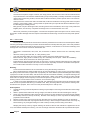
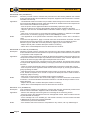
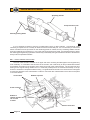
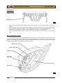
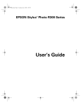
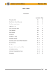
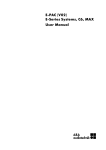
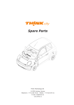
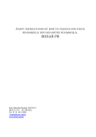
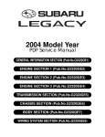
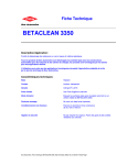
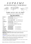
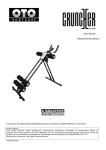
Lotus Service Notes
Section BQ
BODYCARE & REPAIR
SECTION BQ
Sub-Section Page
General Description
BQ.1
3
Lotus Composite Body Features
BQ.2
3
Bodycare
BQ.3
4
Accident Damage Assessment
BQ.4
5
Body Panel Bonding Materials
BQ.5
6
Replacement of Bonded-On Panels - General
BQ.6
9
Front Crash Structure
BQ.7
10
Windscreen Frame
BQ.8
12
Sill Panels
BQ.9
16
Rear Bulkhead
BQ.10
17
Page 1
Lotus Service Notes
Section BQ
Body Panels
Front access
panel
Windscreen
frame
Door
shell
Sill panel
Rear
window
shroud
Engine
cover lid
Front
clamshell
Cabin rear
bulkhead
Door hinge
cover panel
Rear clamshell
Front crash
structure
Chassis frame
b277b
Page 2
Lotus Service Notes
Section BQ
BQ.1 - GENERAL DESCRIPTION
The body panels of the Lotus Elise are constructed of composite materials, with the external panels not
being required to contribute to chassis rigidity. The panels are attached to the aluminium chassis and/or other
body panels either by elastomeric polyurethane adhesive, or in the case of the front and rear clamshells, are
bolted on for ease of dis-assembly and access to chassis parts. The composite mouldings are manufactured
by one of several processes (see later) dependent on application, with a nominal thickness of 2.2 - 2.5 mm.
The windscreen frame incorporates foam beams to create closed box sections for optimum strength and a
‘crash structure’ bonded to the front of the chassis incorporates longitudinal box sections to provide specific
crush characteristics and absorb crash impact by progressive collapse. This structure also acts as a mounting
and duct for the engine cooling radiator which is mounted horizontally on its top surface.
BQ.2 - LOTUS COMPOSITE BODY FEATURES
Composite structures have the ability to absorb high impact loads by progressive collapse, with impact
damage being localised. In vehicle accidents this feature protects the occupants from injurious shock loads and
greatly reduces the danger of entrapment by deformation of steel body panels. This behaviour also facilitates
repair by either replacing the damaged bonded or bolt on panels, and/or integrating a replacement section
with the undamaged area, using recognised approved methods which restore the panel to its original condition
without residual strain or distortion.
The manufacturing process enables the thickness of composite mouldings to be varied in order to provide
efficient structures of high strength and low weight. Composites will not corrode, so the strength of composite
components is retained regardless of age, unless physical damage is sustained. On the Elise, the body construction features an assembly of mouldings to form a single piece for the whole of the nose and front wings,
and a similar assembly for the whole of the rear body aft of the doors. These two 'clamshells' are fixed using
threaded fasteners to permit easy removal for access to chassis or powertrain components, or to allow simple
and economic accident repair. Other composite mouldings include the door shells, sills, front compartment
lid, windscreen frame and rear bulkhead, some panels being bonded to the aluminium alloy chassis with an
elastomeric adhesive.
A composite panel may return to its original shape after deflection, but beyond a certain level of flexibility,
such treatment may result in the formation of surface cracks which may not be immediately apparent due to
the masking effect of the paint film. A steel panel similarly treated would become dented or deformed. The
cracking may be confined to the surface layer with no reduction in panel strength, but if the damage is more
severe the composite structure below the surface may be weakened. Localised repairs can be made in either
case. Possible causes of surface cracking include:
-
Vehicle collision;
Sitting, leaning heavily or pushing on the body or any composite panel;
Knocking doors against obstructions when opening;
Dropping objects onto a panel;
Allowing unrestrained items to roll about in a luggage compartment;
Fitting a front access panel or closing the engine cover onto projecting objects, e.g. luggage or tools;
Applying excessive force to parts attached to composite panels e.g. mirrors, locks, aerial etc. (inc. action
byvandals).
Incorrect jacking.
The composite body panels of the Elise are manufactured by one of several processes dependent on the
requirements of the panel concerned:
-
The front and rear clamshells, sill panels, windscreen frame, door outer panels, hard top roof outer panel
and front crash structure are produced by Injection Compression System Resin Transfer Moulding (ICSRTM), whereby a mix of polyester resin and glass fibres is injected into a heated, chrome steel surfaced,
closed mould. After filling, the gap between the two halves of the mould is then reduced in order to compress the moulding and ensure complete material flow and consistent structural quality. Panel thickness
is a nominal 2.2 mm. The absence of the 'gel coat' used with other processes results in much greater
resistance to surface damage, and minimum surface preparation for before painting.
Page 3
Lotus Service Notes
-
-
Section BQ
The front access panels, engine cover lid, door hinge panels, door and roof inners and rear window shroud
are produced from Low Pressure Sheet Moulding Compound (LPSMC), whereby flat sheets of composite
material are formed using heated, chrome steel surfaced moulds to produce panels with a nominal thickness of 2.5 mm.
A third process is used for the cabin rear bulkhead, bootbox and radiator mounting panel where the panel
surface is not primarily visible. These panels are produced by a Polyurethane Structural Reaction Injection Moulding (PU SRIM) process.
Body panels unique to the Exige model, including front and rear clamshells, door hinge cover panels and
tailgate panel, are 'hand lay' composite mouldings with a nominal thickness of 2.5 mm.
Whichever production process applies, conventional composite repair techniques can be used to rectify
structural or surface damage whenever repairs can be determined as being more economic than panel replacement.
BQ.3 - BODYCARE
The acrylic enamel paint finish of the Elise is extremely resistant to all normal forms of atmospheric attack.
Following the simple maintenance procedure summarised below will help retain the gloss, colour and protective
properties of the paint throughout the life of the vehicle. However, car finishes are not immune to damage, and
amongst the more common causes of deterioration are:
-
Atmospheric contaminants; dust, soot, ash, and acidic or alkaline aerosol mist can chemically attack
paint.
Abrasion; blowing sand and dust, or a dirty washing cloth.
Tree sap and insect fluids; can form a water-insoluble polymer that adheres to the paint.
Bird excrement; highly acidic or alkaline, they can chemically etch the paint. Wash off immediately.
Leaves; contain tannic acid which can stain light finishes.
Impact damage; granite chippings thrown up from poor or recently dressed road surfaces can subject the
body to severe localised impact, and result in paint chips, especially around the vulnerable frontal panels.
Do not follow other vehicles too closely in such circumstances.
Washing
Lotus recommends that the car be hand washed, using the following instructions:
Many contaminants are water soluble and can be removed before any harm occurs by thorough washing
with plenty of lukewarm water, together with a proprietary car wash additive (household detergent and washing
up liquid can contain corrosive salts, and will remove wax and accelerate oxidation). Frequent washing is the
best safeguard against both seen and invisible contaminants. Wash in the shade, and use a cotton chenille
wash mitt or a sponge rinsed frequently to minimise entrapment of dirt particles. Use a straight back and forth
washing motion to avoid swirled micro scratches, and rinse thoroughly.
In order to minimise degradation from road salt, the underside of the chassis should be rinsed with clean
water as soon as possible after driving on treated roads. Many fuel filling stations offer pressure washing facilities ideal for this purpose, but to not use on the painted bodywork or soft top roof.
Soft Top Roof:
1. Careful vacuuming of the soft top before washing may be helpful in removing excess dust and other foreign
particles.
2. Wash in partial shade rather than strong sunlight, and wet the whole car before tackling the soft top.
3. Using only clean lukewarm water and a sponge (a chamois or cloth will leave lint, and a brush may abrade
the threads) wash the entire top uniformly. Do NOT use a detergent, which may affect the waterproofing
properties of the material.
4. Rinse the whole car to remove all soap from the fabric and to prevent streaking on the car bodywork.
5. Remove surface water with a sponge and allow to air dry in direct sunlight. Ensure that the roof is fully dry
before stowing, as prolonged stowage of a wet or damp roof will promote rotting of the fabric.
Keeping the soft top clean by regular washing will enhance the life and maintain the appearance of the
roof, and facilitate subsequent cleaning. The use of stronger cleansers should be left to professionals experiPage 4
Lotus Service Notes
Section BQ
enced in handling this type of fabric as discoloration and degradation of the special protective inner layer may
result. The application of wax finishes, dressings or preservatives will cause stains which are difficult to remove
and therefore should be avoided.
Paintwork Polishing
Eventually some loss of gloss, and an accumulation of traffic film, will occur. At this stage, after normal
washing, the application of a good quality liquid polish will restore the original lustre of the paint film. Higher
gloss of the paint finish, and added protection against contamination, can be obtained by the use of a wax
polish; however, this can only be used successfully on a clean surface, from which the previous application has
been removed with white spirit or a liquid polish cleaner.
Ventilation
Water lying on the paint surface for a lengthy period will eventually penetrate the paint film. Although the
effects will not be visible immediately, a deterioration in the protective properties of the paint film will ultimately
result. It is not recommended to store a wet car in a poorly ventilated garage. If good ventilation cannot be
provided, storage outside on a hard standing or under a carport is to be preferred.
BQ.4 - ACCIDENT DAMAGE ASSESSMENT
The repair method to be employed in the rectification of accident damage to composite panels, is to be
assessed reletive to the particular panel and its method of attachment:
Bolt-on Panels:
- Front Clamshell;
- Rear Clamshell;
- Door Shells;
- Front Body Access Panels;
- Engine Cover Lid;
- Door Hinge Cover Panels;
- Rear Window Shroud;
- Hard Top Roof.
These panels are secured by threaded fasteners and are easily removed for access to the back of any
damaged area for repair by conventional composite techniques. Instructions for the removal and refitment of
these panels are contained in section BR.
Bonded-on Panels:
- Windscreen Frame;
- LH & RH Sill Panels;
- Front Crash Structure;
- Rear Bulkhead
These panels are bonded to the chassis or to other panels using a flexible polyurethane adhesive which
must be cut before the panel may be removed. In some cases, it may be necessary to partially remove another
panel before the subject panel can be released. It is not generally economic to attempt to remove a bonded
panel intact for later re-fitment.
The integrity of the front crash structure is crucial to the safety of the car in a frontal collision, and it is recommended not to attempt any major repair of this component. The damaged structure should be cut from the
front of the chassis, and a new assembly bonded into position. The shape and positioning of the windscreen
frame is crucial to the fit of the windscreen and sealing of the soft top roof, such that the only repairs which
should be considered for this panel are cosmetic and superficial; any structural damage should entail panel
replacement.
The sill panels include the ‘A’ and ‘B’ posts, and involve much labour time to replace. Localised repairs
should be performed whenever possible, although access to the inside surface of some parts of the panels is
not freely available.
Note that if damage is such as to require replacement of the chassis, replacement chassis assemblies are
provided only as a 'partial body assembly' which includes jig bonded front crash structure, windscreen frame,
side sills and rear bulkhead. The roof hoop and rear subframe are also included, as are the pipes, hoses and
cables routed through the sills.
Page 5
Lotus Service Notes
Section BQ
BQ.5 - BODY PANEL BONDING MATERIALS
The materials used for bonding the body panels are manufactured by Dow Chemical, and in order to
maintain the structural integrity of the vehicle, and in the case of the front crash structure, the safety, it is most
important to use only the specified materials. The surface preparation and cleaning and priming operations are
crucial to the performance of the adhesive, and must be followed in detail. The products to be used depend on
the surface (substrate) onto which they are applied, and the following list identifies each application:
Anodised aluminium (e.g. chassis and components)
Cleaner:
Betawipe VP 04604
Lotus part no. A082B6150V
Primer:
Betapnme 5404
Lotus part no. A082B6337V
Adhesive:
Betaseal 1701
Lotus part no. A082B6281F
or Betamate E2400
Lotus part no. A082B8415V
Unpainted or painted composite
Cleaner:
Betaclean 3900
Primer:
Betaprime 5404
Adhesive:
Betaseal 1701
or Betamate E2400
Lotus part no. A100B6008V
Lotus part no. A082B6337V
Lotus part no. A082B6281F
Lotus part no. A082B8415V
Zinc plated and passivated steel
Cleaner:
Beatclean 3900
Primer:
Betaprime VP 01706 A+B
Adhesive:
Betaseal 1701
Lotus part no. A100B6008V
Lotus part no. A100B6070V
Lotus part no. A082B6281F
Glass
Cleaner:
Primer:
Adhesive:
Betawipe VP 04604
Betaprime 5001
Betaseal 1701
or Betamate E2400
Lotus part no. A082B6150V
Lotus part no. A100B6009V
Lotus part no. A082B6281F
Lotus part no. A082B8415V
Uncoated Lexan/Perspex
Cleaner:
Abrasion & dry wipe
Primer:
Betapnme 5404
Adhesive:
Betaseal 1701
or Betamate E2400
Lotus part no. A082B6337V
Lotus part no. A082B6281F
Lotus part no. A082B8415V
Residual adhesive (i.e. rebonding to surface after cutting off old panel)
Cleaner, primer
& re-activator: Betawipe 4000
Lotus part no. A082B6355V
Adhesive:
Betaseal 1701
Lotus part no. A082B6281 F
or Betamate E2400
Lotus part no. A082B8415V
Applicator Bottle
An applicator bottle is available for use with some cleaners and primers, and has a disposable felt pad
which should be changed regularly to minimise surface contamination:
Applicator bottle:
A000Z1071F
Cap:
A082B6353S
Felt pad:
A082B6354S
Product Usage
BETAWIPE VP 04604 (A082B6150V):
Description:
Activator and cleaning agent used to promote adhesion to the substrate surface. Supplied in
a 250ml aluminium container with a YELLOW coloured cap.
Application:
- Wipe on/wipe off type.
- Pour Betawipe VP 04604 into applicator bottle, and immediately refit the yellow cap onto the
container.
Page 6
Lotus Service Notes
Notes:
Section BQ
- Push the applicator head onto the bottle, and fit the felt pad.
- Wet out the felt pan by inverting the applicator bottle and gently squeezing the sides.
- Wipe the pad over the substrate surface using minimal pressure to wet the surface.
- Immediately wipe off the activated/cleaned surface using a clean fibre free cloth, and discard.
- If the substrate is very dirty, first wipe off the surface with a clean fibre free cloth and discard.
- Do not leave the caps off Betawipe containers. A milky colour indicates moisture absorption,
and the material should be discarded.
- Only decant a sufficient quantity of Betawipe for the job concerned, and never pour material
back into the container from the applicator bottle.
- Change the felt pad at regular intervals to reduce surface contamination.
BETACLEAN 3900 (A100B6008V)
Description:
Degreaser and cleaning agent used for the removal of contamination from the substrate surface.
Supplied in 1 litre aluminium container with a BLACK coloured cap.
Application:
- Wipe on/wipe off type.
- When substrate is very dirty, first wipe off the surface with a clean fibre-free cloth and discard.
- Dampen a fibre-free cloth with Betaclean 3900, and immediately replace the black cap.
- Thoroughly clean the substrate surface with Betaclean and discard the cloth.
- Wipe off the substrate with a clean fibre-free cloth and discard.
BETAWIPE 4000 (A082B6355V)
Description:
Cleaning agent which acitvates the old adhesive layer to accept new adhesive. Supplied in 250
ml aluminium containers with a BLUE cap.
Application:
- The residual adhesive bead should be cut with a scalpal to leave an even thickness of approximately 1 to 2 mm.
- Dampen a fibre-free cloth with Betawipe 4000 and immediately replace the blue cap.
- Thoroughly clean the substrate surface with Betawipe and discard the cloth. Do not wipe
off.
- Allow 2 - 3 minutes flash off time before applying adhesive.
BETAPRIME 5001 (A100B6009V)
Description:
Adhesion promotor used to maximise the performance of the bonding between the cleaned
and/or activated surface and the adhesive compound. Supplied in 250 ml aluminium container
with GREEN coloured cap.
Application:
- Two steel balls inside the container are provided to assist mixing of the contents when shaken.
Prior to decanting Betaprime 5001, shake the container for at least 60 seconds to disperse the
solid content of the material into suspension.
- Pour the primer into the applicator bottle and immediately replace the green cap.
- Wet out the felt pan by inverting the applicator bottle and gently squeezing the sides.
- Wipe the pad over the activated/cleaned substrate surface to apply a continuous film of
primer.
- Allow to dry for a minimum of 15 minutes before applying adhesive. If adhesive is not applied
with 72 hours, wipe on/wipe off with Betawipe VP 04604.
Notes:
- The appearance of the primed areas should be deep black in colour with no streaks or
voids.
To achieve this appearance, apply in smooth continuous uni-directional movement, not short
backward and forward movements. The latter technique results in inconsistent film build.
Rework any poor areas after 5 minutes (tack time), applying in the same direction.
- Replace the felt pad if moisture absorption results in hardening.
- Never return unused Betaprime back into the aluminium container.
Page 7
Lotus Service Notes
Section BQ
BETAPRIME 5404 (A082B6337V)
Description:
Adhesion promotor used to maximise the performance of the bonding between the cleaned
and/or activated surface and the adhesive compound. Supplied in 250 ml aluminium container
with RED coloured cap.
Application:
- Two steel balls inside the container are provided to assist mixing of the contents when shaken.
Prior to decanting Betaprime 5404, shake the container for at least 60 seconds to disperse the
solid content of the material into suspension.
- Pour the primer into the applicator bottle and immediately replace the green cap.
- Wet out the felt pan by inverting the applicator bottle and gently squeezing the sides.
- Wipe the pad over the activated/cleaned substrate surface to apply a continuous film of
primer.
- Allow to dry for a minimum of 15 minutes before applying adhesive. If adhesive is not applied
with 24 hours, re-activate by applying a further coat of Betaprime 5404.
Notes:
- The appearance of the primed areas should be deep black in colour with no streaks or
voids.
To achieve this appearance, apply in smooth continuous uni-directional movement, not short
backward and forward movements. The latter technique results in inconsistent film build.
Rework any poor areas after 5 minutes (tack time), applying in the same direction.
- Replace the felt pad if moisture absorption results in hardening.
- Never return unused Betaprime back into the aluminium container.
BETAPRIME VP 01706 A+B (A100B6070V)
Description:
Adhesion promotor used to maximise the performance of the bonding between the cleaned
and/or activated surface and the adhesive compound. Supplied in 250 ml aluminium containers
of component A and component B.
Application:
- Thoroughly shake component A container to disperse solid material. Remove the lid from the
component A container and scrape any sediment from the botton of the container. Replace the
container lid and thoroughly shake again to disperse the solid content.
- Pour the required amount of component A into a clean container, and add the same volume
of component B. Replace lids immediately. Thoroughly mix the two components for 45 seconds
minimum.
- Leave the mixed components to stand for 30 MINUTES. (Discard if unused after 8 hours)
- Pour the pnmer into the applicator bottle and wet out the felt pan by inverting the bottle and
gently squeezing the sides.
- Wipe the pad over the cleaned substrate surface to apply a continuous THIN film of primer:
A thin, almost transparent film is all that is required. No attempt should be made to attain a
completely opaque covering.
- Allow to dry for a minimum of 4 HOURS, before applying adhesive.
Notes:
- To achieve a continuous thin film of VP 01706, apply in a smooth continuous uni-directional
movement, not short backward and forward movements. The latter technique results in inconsistent film build.
- Replace the felt pad if moisture absorption results in hardening.
- Never return unused Betaprime back into the aluminium container.
BETASEAL 1701 (A082B6281F)
Description:
One component moisture curing adhesive, providing high strength, permanently elastic bonds
between various substrates. Supplied in 300 ml aluminium cartridge.
Application:
- Remove the cartridge end ensuring there is no damage to the reinforcing sleeve.
- Pierce the neck of the cartridge and screw on the applicator nozzle. Cut the nozzle end to the
required diameter and shape.
- Fit the cartridge into an air assisted gun, and extrude a smooth, even and continuous bead
of Betaseal to the previously prepared substrate.
- Assemble the joint within 5 MINUTES.
Notes:
- If the adhesive has to be touched or manipulated for any reason, use only wetted fingers.
Page 8
Lotus Service Notes
Section BQ
BETAMATE E2400 (A082B8415V - 220ml, A100B6258V - 450ml)
Description:
Two component chemically curing adhesive, providing high strength, permanently elastic bonds
between various substrates. Supplied in 220 and 450 ml aluminium cartridges.
Application:
- An electrically driven Betagun Mk 11 is required to mix and extrude Betamate E2400. Refer
to the operating instructions supplied with the gun.
- Extrude a smooth, even and continuous bead of Betamate to the previously prepared substrate.
- Assemble the joint within 5 MINUTES.
Notes:
- If the adhesive has to be touched or manipulated for any reason, use only wetted fingers.
Air gun
Betaseal cartridge
bj43
BQ.6 - REPLACEMENT OF BONDED-ON PANELS - GENERAL
Bonded body panels are secured using the Gurit-Essex products ‘Betaseal’ or ‘Betamate’, which are flexible polyurethane adhesives which must be cut in order for a panel to be removed. The recommended method
of adhesive cutting is with the use of a pneumatic tool such as the Chicago Pneumatic CP838 PneuNife which
uses a range of differently shaped cutting knives to which is imparted a vibrating action. This tool may also be
used to remove windscreens.
Supplier:
Catalogue no.:
Recommended air pressure:
Tool air inlet:
Chicago Pneumatic, Utica, New York 13501, USA.
CP838 Pneu-Nife
60 - 90 PSIG (4.0 - 6.2 bar)
1/4” NPTF, 3/8” mm. hose size
Page 9
Lotus Service Notes
Section BQ
Operating handle
Compressed air inlet
Vibrating cutting blade
bj46
It is not generally practical to remove a bonded panel intact, for later refitment. Consequently, when
necessary, the panel can be cut away for better access to the bonded joint. It is not necessary to remove all
traces of sealant from the joint faces on the remaining panels or chassis, but any remaining sealant must be
securely bonded and no thicker than 1 mm or the fit and joint gaps will be upset. It is essential always to follow
the cleaning/priming/bonding operations meticulously if sufficiently strong and durable bonds are to be obtained.
Always use the specified materials.
BQ.7 - FRONT CRASH STRUCTURE
The front crash structure consists of an upper and lower moulding bonded together and supplied only
as an assembly. It is bonded to the front face of the chassis, and is braced by an alloy undershield screwed
to the bottom front edge of the chassis, and to each lower side of the crash structure. The unit also acts as a
ducting for the engine cooling radiator and a.c. condenser (if fitted) which are mounted horizontally on its top
surface in a bolted-on composite radiator housing. Longitudinal tubes formed in the construction are designed
to produce a particular crush characteristic in order to control the rate of deceleration of the vehicle occupants
in a frontal collision.
Crush tubes
Radiator aperture
Crash structure
Airflow to
climate chamber
via cut outs
in tubes
Chassis front face
p84a
Page 10
Lotus Service Notes
-
-
Section BQ
To remove the crash structure:
Remove the front clamshell (see sub-section BR.5).
Remove the front undershield by releasing the three screws securing each lower side of the structure to
the shield, and the three screws securing the shield to the front lower edge of the chassis.
Drain the coolant and remove the radiator and pipework (see section KH).
Remove the driving lamps (if fitted) from the crash structure, along with the towing strut, horn, alarm siren
and wiring harness.
Use a seal cutting knife to cut the bond between the structure and the front face of the chassis. For access
to some of the bonding areas, it may be necessary to cut away some parts of the structure, rendering the
unit unsuitable for refitment. Take care not to damage the surface of the chassis when cutting the adhesive.
It is not necessary to remove all traces of old adhesive from the chassis, but a uniform surface must be
available for the new adhesive bead. The remaining adhesive must be securely bonded and be cut with
a scalpal blade to leave an even thickness of 1 - 2 mm.
Prepare the new structure for bonding:
Dry fit the new structure to the chassis, and check that a good fit is achieved. Fettle the structure or remove
old adhesive as necessary until the fit is satisfactory.
Re-activate the surface of the old adhesive on the chassis using Betawipe 4000 (see sub-section BQ.5),
and clean and prime the bonding area on the new crash structure using Betaclean 3900 and Betaprime
5404 (see sub-section BQ.5).
Bonding surface on chassis
Composite crash
structure
b278a
Page 11
Lotus Service Notes
Section BQ
Application of
adhesive bead
Betaseal bead
b279
-
Apply a bead of Betaseal/mate adhesive (see sub-section BQ.5) to the bonding surface in the manner
shown.
Fit the structure to the chassis and press into position to spread the adhesive. Use several clamps around
the joint flange to retain the structure until the adhesive has cured; This will take approximately 4 hours
dependent on atmospheric conditions, with a longer period required in dry atmospheres.
Fit the undershield, radiator (see sub-section KH.4), front clamshell (see sub-section BR.5) and remaining
parts.
BQ.8 - WINDSCREEN FRAME
The windscreen frame is a single ICSRTM moulding with hollow, foam filled sections, and incorporates a
forward extending buttress at each side to brace the frame against the front chassis. A separate dash baffle
panel is used to bridge the space between frame underside and chassis scuttle, and provide for the routing of
climate control pipework and air ducting, and other services.
Windscreen frame
Dash baffle panel
Demist air duct
Face level
vent duct
Chassis scuttle
Heater pipe
b282b
Page 12
Lotus Service Notes
Section BQ
The shape of the frame is critical to the windscreen fit, and structural repairs to the frame itself are not
recommended. It is not generally economic to attempt to remove the windscreen frame intact for refitment,
as the elastomeric adhesive bonding the frame to the chassis requires cutting with a reciprocating knife, and
access to the joints is sometimes obscured. The recommended procedure is to cut the frame as necessary to
allow its removal without damage to the dash baffle panel. If the sills are to remain fitted, it will be necessary
to carry out some minor work on the screen buttress to sill panel joint, where a panel overlap occurs.
To Replace Windscreen Frame
1. Remove the front wheelarch liners and front clamshell (see sub-section BR.5), and for improved access,
the two doors.
2.
Remove the windscreen (see sub-section BR.14).
3.
Remove the instrument binnacle and fascia top panel (see sub-section BR.13), and release the fixings
between dash upper extrusion and screen frame.
4.
Release the brake hose/pipe connector at the front end of each buttress on the windscreen frame. Release
all harnesses and other components from the windscreen frame buttresses as necessary.
5.
Remove the wiper motor mechanism from the windscreen frame.
6.
Use a sealant cutting tool to cut the bond between the windscreen frame buttresses and chassis, and
between the frame and 'B' posts, and between the frame underside and dash baffle panel. Remove the
windscreen frame.
7.
Cut the adhesive securing the drainage gutter around the front of the frame, to allow transfer to the new
frame.
8.
If the dash baffle panel is to be replaced, the clutch pipe and climate control cables must be released and
threaded through the panel before cutting the adhesive.
Primer band on chassis
Primer band on baffle
Heater pipe grommet
Dash baffle panel
Foam strip
b283b
Page 13
Lotus Service Notes
9.
Section BQ
To fit a new dash baffle:
- Ensure the heater feed and return pipes are fitted.
- Dry fit the panel and mark up the bonding surface on the chassis scuttle.
- Prepare and re-activate the surface of the old adhesive on the chassis using Betawipe 4000 (see
BQ.5).
- Clean and prime the upper and lower bonding faces on the new baffle panel using Betaclean 3900 and
Betaprime 5404 (see sub-section BQ.5).
- Apply a bead of Betaseal/mate adhesive (see sub-section BQ.5) to the baffle lower flange.
- Position the panel and press along the length of the joint to ensure sufficient spread of adhesive. Clamp
the panel in position until the adhesive cures.
- Apply self adhesive foam strip A082U6065V to each vertical end face of the baffle panel, wrapping over
onto the top edge and along to the primed surface. Apply a second strip up each vertical face.
10. Prepare the old adhesive bead on the chassis for fitment of the windscreen frame by removing excess
sealant from all the bonding areas on the chassis, sill panels and dash baffle to leave a consistent and
level bonding surface for the new frame. It is not necessary to remove all traces of old adhesive, but a
uniform surface must be available for the new adhesive bead. The remaining adhesive must be securely
bonded and be cut with a scalpal blade to leave an even thickness of 1 - 2 mm.
11. Fit the wiper motor assembly and windscreen washer jets to the windscreen frame.
12. If necessary, fit a new roof side rail latch plate to the windscreen header rail - it is not recommended to
refit a bracket due to the requirement for high surface quality on the bracket.
- If applicable, completely remove any old adhesive from the header rail taking care not to damage the composite substrate. Lightly abrade the bonding surface on the header rail but do not abrade the bracket.
- Clean the bonding surfaces on the header rail and bracket with Betaclean 3900 (see sub-section
BQ.5).
- Prime the header rail with Betaprime 5404, but do not prime the bracket.
- Generously coat the bonding surface of the bracket, with a 50/50 mix of Betamate 7064S (A116B0159V)
and Betamate 7014 (A116B0158V). Fit the bracket to the header rail and wipe off extruded adhesive with
Betaclean 3900. Position the bracket using tool T000T1422F (RH) or T000T1423F (LH), which sould be
taped to the header rail for at least 30 minutes.
13. Before fitting the windscreen frame, ensure that two setting rods are available for positioning the frame:
- Cut two 670mm lengths of locally sourced 10mm diameter steel rod.
14. - Prepare and re-activate the old adhesive bead on the chassis using Betawipe 4000 (see BQ.5).
- Clean and prime the bonding area on the new windscreen frame with Betaclean 3900 and Betaprime
5404 (see sub-section BQ.5).
- Apply a bead of Betaseal/mate adhesive (see sub-section BQ.5) to the whole of the bonding flange on the
windscreen frame and butresses, including the mating face between frame underside and baffle panel.
- Carefully fit the windscreen frame onto the chassis and press into position to ensure adequate adhesive
compression. Ensure the frame is positioned correctly in relation to the roll-over bar by fitting the two setting rods in the roof siderail locating slots. The rods should locate snugly in the slots with no end play.
- Clamp the frame into position until the adhesive cures.
- Ensure good adhesion between the frame and baffle panel.
- Use a spatula to smooth out or remove any excess or extruded adhesive.
15. Seal the frame panel to the top of the door hinge post at each side by extruding a bead of Betaseal, and
smoothing with a spatula to obtain a neat finish.
16. Examine the whole of the bonding jointline for sealing integrity, and if necessary apply additional adhesive
to seal any gaps. Use a spatula to smooth any visual areas to a neat finish.
17. Do not disturb the frame until the adhesive has fully cured (see sub-section BQ.5).
18. Fit the windscreen (see sub-section BR.14), dash panel and instrument pack (BR.13), front clamshell
(BR.5), and other components as necessary.
Page 14
Lotus Service Notes
Section BQ
Windscreen frame bonding (sills not shown)
Windscreen frame
Windsceen
frame
buttress
Dash
baffle
panel
Bonding path
b281a
Page 15
Lotus Service Notes
Section BQ
BQ.9 - SILL PANELS
The sill panels incorporate the ‘A’ and ‘B’ posts, and are bonded to the chassis, windscreen frame and
rear bulkhead panel. The sill bottom flange, and rear end of the will top flange are bonded into grooves in the
chassis main side rails and it is necessary to cut the sills in the course of their removal: It is not practical to
attempt to remove a sill panel intact for later refitment. If sill damage occurs which is not repairable ‘in situ’,
the sill panel should be renewed.
To Replace Sill Panel
A short section of sill flange underlaps the windscreen frame buttress flange in the front wheelarch area
and requires that some cutting and laminating of the new panel is required on assembly.
1.
Remove front and rear clamshells (see sub-sections BR.5, BR.6), dash panel (BR.13) and door hinge
bracket (BR.8).
2.
Remove the door latch striker pin and washers, noting the assembly sequence. Remove the door sill trim
panel from the chassis and the door ajar switch from the sill panel.
3.
Use a sealant cutting knife to cut the adhesive bead between sill and chassis/body panels.
Note:
- In the front wheelarch area, a short section of the sill flange underlaps the windscreen frame buttress
flange. Unless the windscreen is also to be removed, it will be necessary to cut the sill around this flange
in order to release the sill.
- The bottom edge of the sill, and the rear part of the top edge, locate in grooves in the chassis side frame,
and may not readily be cut out with the sill intact. Cut the sill as necessary to release the panel, and then
remove the remaining edges of the panel from the chassis using a suitable cutting knife.
- Cut the sealant around the door hinge post aperture.
- Cut the sealant between the panel and roll over bar.
Door hinge
post
Cut flange
top corner
if necessary
Slots in chassis
siderail
Bonding path
Sill panel
bj47a
Page 16
Lotus Service Notes
Section BQ
4.
Remove excess sealant from all the bonding areas on the chassis and body panels. It is not necessary to
remove all traces of old adhesive, but any remaining adhesive must be securely bonded and be cut with
a scalpal blade to leave an even thickness of 1 - 2 mm.
5.
If necessary, cut the top front corner of the sill flange to allow mating of the panel around the windscreen
butress flange. Dry fit the sill and fettle as necessary to achieve a good fit. Note that a new sill will require
an alloy right angle bracket (A120B0053F) riveting to the rear end of the sill panel to form a bonding surface.
Holes are pre-drilled, with two pairs of holes in the bracket to suit Rover and Toyota powertrain cars. For
Toyota powertrain cars, use the innermost holes in the bracket to pull the sill panel furthest inboard.
6.
Before preparing the surfaces for bonding, ensure that the necessary pipes and cables are fitted to the
chassis side rails:
RH side: - heater feed pipe
- brake pipe
- alloy spigot for side impact foam
LH side: - heater return pipe
- brake pipe
- clutch pipe
- servo vacuum hose
- main battery positive cable
- alloy spigot for side impact foam
Check that the following components are fitted into the composite sill:
RH side: - 2 a.c. pipes (if applicable)
- oil cooler return hose (if applicable)
- side impact foam
- foam baffle
LH side: - oil cooler feed hose (if applicable)
- side impact foam
- foam baffle
7.
Prepare the bonding surface of the new sill panel with Betaclean 3900 and Betaprime 5404 (see subsection
BQ.5). Prepare surface of the old adhesive bead on the chassis and body panels Using Betawipe 4000
(see sub-section BQ.5).
8.
Apply a bead of Betaseal/mate adhesive (see sub-section BQ.5) to the bonding surface on the chassis and
body and fit the sill panel into position, first locating the sill bottom edge into its chassis slot, and press all
around the joint to ensure sufficient spread of adhesive. If necessary, use a spatula to smooth or remove
any extruded adhesive, and to neaten any visual areas. If necessary, add adhesive to the joint around
the door hinge post, and to the windscreen frame, and smooth with a spatula.
9.
Clamp the panel into position until the adhesive has cured (see sub-section BQ.5).
10.
If the top front corner of the sill flange has been cut to fit around the windscreen butress flange, this area
should be reinforced as follows: Roughen the surface of the windscreen buttress flange and the adjacent
sill panel in the modified area, and lay up two pieces of chopped strand mat across the joint.
11.
Refit the dash panel, front and rear clamshells, doors, both wheelarch liners and other components as
necessary.
BQ.10 - REAR BULKHEAD
The rear bulkhead is a Polyurethane Structural Reaction Injection Moulding (PU SRIM), incorporates the
rear window surround, and is bonded to the roll over bar and chassis fuel tank bay. A heat formed polyester
fibre heat/acoustic insulator panel is bonded to the rear side of the panel, and incorporates a glass fibre aluminised cloth heat reflector shield in the vicinity of the exhaust manifold. The rear window is bonded directly
to the bulkhead using the same materials and procedure as is used for the windscreen.
Page 17
Lotus Service Notes
Section BQ
To replace the rear bulkhead:
1.
Remove the rear clamshell (see sub-section BR.6).
2.
Remove both seats, and the bulkhead interior trim panel.
3.
Remove from the inside of the bulkhead the microwave sensor and immobiliser module. Release all wiring
harnesses from the bulkhead clips.
4.
Release all fittings from the roll-over bar backstays (air cleaner, roll over valve) and remove both backstays.
5.
Taking suitable precautions, remove the fuel filler hose and filler breather hose, and cap the tank apertures
to prevent dirt ingress and reduce fire risk.
6.
Release the evaporative emissions charcoal canister and fuel filter from their bulkhead mounting brackets.
7.
Release the aerial lead from the bulkhead.
8.
Using a long knife, cut the adhesive securing the insulator panel to the bulkhead, and remove the panel
to improve access to the bulkhead bonded joint.
9.
Using a sealant cutting knife, cut the adhesive bead between the top section of the bulkhead and the roll
over bar, and between the bottom of the bulkhead and the chassis. If the sill panels are fitted, cut the
bond between sill panel 'B' posts and the bulkhead panel.
10.
Manoeuvre the bulkhead from the car.
To Fit Bulkhead Panel
Before fitting a bulkhead panel, ensure that the following parts are bonded to the panel:
- Header tank mounting bracket;
- Charcoal canister mounting bracket;
- Immobiliser module stud plate;
- Fuel filter mounting bracket;
- Rear window glass;
All the above components are bonded using elastomeric adhesive applied as follows. Refer also to subsection BQ.5:
Brackets & Studplates: Clean the bonding surfaces on the bracket and bulkhead with Betaclean 3900 (black
cap) and prime both surfaces with Betaprime 5404 (red cap). Apply Betaseal 1701 adhesive to the bracket,
and clamp in position until the adhesive has cured.
Rear Window: Clean the whole of the bonding surface on the glass with Betawipe VP 04604 (yellow cap), and
prime with Betaprime 5001 (green cap). Clean the corresponding surface on the bulkhead with Betaclean 3900
(black cap) and prime with Betaprime 5404 (red cap). Apply a bead of Betaseal 1701 to the periphery of the
glass, and press into position on the bulkhead to ensure sufficient compression of the adhesive. Use a spatula
to remove excess extruded adhesive and smooth any visual areas. Tape the glass into place if necessary to
retain position until the adhesive cures.
Bonding of Bulkhead Panel: Clean the mating surfaces of bulkhead, roll over bar and (if fitted) sill 'B' posts,
with Betaclean 3900 (black cap) and prime with Betaprime 5404 (red cap). Or, where applicable, use Betawipe
4000 to re-activate old adhesive (refer to sub-section BO.5). Clean the mating surface on the chassis with
Betawipe VP 04604 (yellow cap), and prime with Betaprime 5404 (red cap). Apply a bead of Betaseal 1701
to the bonding path on the bulkhead, and manoeuvre into postion, pressing all round the joint path to ensure
sufficient compression of the adhesive. Use a spatula to remove excess extruded adhesive and smooth any
Page 18
Lotus Service Notes
Section BQ
visual areas. Secure in position with tape until the adhesive has cured.
The heat/acoustic insulator panel is bonded to the bulkhead only at its centre section. Clean and prime
the centre section on the bulkhead with Betaclean 3900 and Betaprime 5404, and apply Betaseal 1701. Press
the insulator panel into position and ensure sufficient compression of adhesive. Tape in place until the adhesive
has cured.
Refit remaining components in reverse order to removal.
Page 19