1
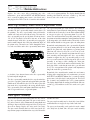
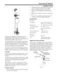
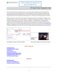
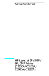
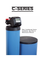
C-SERIES
Water Conditioning System
Installation, Operation &
Maintenance Manual
C-SERIES
The “C-Series” Features
•
•
•
•
•
•
•
•
•
•
•
•
Solid State Microprocessor with Easy Front Panel Settings
Three Modes of Operation…Meter Immediate, Meter Delayed, or Time Clock Delayed
Double Backwash Feature, Offers Optimum Regeneration, Cleaning Ability, and Efficiency
36 Selectable Pre-programmed Regeneration Cycles
Days Override Feature 1 - 28 Days Available
Backwash and Brining Ability To 21" Diameter Tanks
Downflow Regeneration
Stores System Configuration and Operation Data In Non Volatile Memory
Battery Back-up with up to 8 Hour Power Carry Over
12 Volt Transformer Provides Safe and Easy Installation
Provides Optimum Service And Backwash Rates
Treated Water Regenerant Refill
The “C” Series Control Valve Specifications
Inlet/Outlet . . . . . . . . . . . . . . . . . . . . . . . . . . . . . . . . . . . . . . . . . . . . . . . . .1",
Cycles . . . . . . . . . . . . . . . . . . . . . . . . . . . . . . . . . . . . . . . . . . . . . . . . . . . . .3 – 6
Valve Material . . . . . . . . . . . . . . . . . . . . . . . . . . . . . . . . . . . . . .Noryl*
Dimensions
Flow Rates
Service @ 15 psi drop
1" Valve (includes bypass and meter) . . . . . . . .27gpm
11/4" Valve (includes meter) . . . . . . . . . . . . . . . . . . . . . .34gpm
11/4" Valve (includes bypass & meter) . . . . . . . . .32gpm
Backwash @ 25 psi drop
1" Valve (includes bypass and meter) . . . . . . . .27gpm
11/4" Valve . . . . . . . . . . . . . . . . . . . . . . . . . . . . . . . . . . . . . . . . . . . . . .32gpm
11/4" Valve (includes bypass) . . . . . . . . . . . . . . . . . . . . .30gpm
Cv Service
1" Valve . . . . . . . . . . . . . . . . . . . . . . . . . . . . . . . . . . . . . . . . . . . . . . . . . . . . . .7.0
11/4" Valve . . . . . . . . . . . . . . . . . . . . . . . . . . . . . . . . . . . . . . . . . . . . . . . . . . .8.8
Cv Backwash
1" Valve . . . . . . . . . . . . . . . . . . . . . . . . . . . . . . . . . . . . . . . . . . . . . . . . . . . . . .5.4
11/4" Valve . . . . . . . . . . . . . . . . . . . . . . . . . . . . . . . . . . . . . . . . . . . . . . . . . . .6.4
Operating Pressures
Minimum/Maximum
.....................
20 psi - 125 psi
Operating Temperatures
Minimum/Maximum . . . . . . . . . . . . . . . . . . . . . . . . . . . . .40°- 110°F
Regeneration . . . . . . . . . . . . . . . . . . . . . . . . . . . . . . . . . . . . . .Downflow
Distributor Pilot . . . . . . . . . . . . . . . . . . . . . . . .1" (1.050) OD Pipe
Dist. Pilot (11/4" Valve) . . . . .1.32" OD Pipe, 32mm OD
Drain Line . . . . . . . . . . . . . . . . . . . . . . . . . . . . . . . . . . . . . . . . . . . .3/4" or 1"
NPT Brine Line . . . . . . . . . . . . . . . . . . . . . . . . . . . . . . . . . . .3/8" or 1/2"
OD Poly Tube Mounting Base . . . . . . . . . . . . . . . . .2-1/2" – 8
NPSM Height from Top of Tank . . . . . . . . . . . . . . . . . . .7-3/8"
Weight . . . . . . . . . . . . . . . . . . . . . . . . . . . . . . . . . . . . . . . . . . . . . . . .4-1/2 lbs.
Current Draw and Voltage . . . . . . . . . . . . . . . . . . . . .0.5A 110v
Tank Applications
Water Softener . . . . . . . . . . . . . . . . . . . . . . . . . .6" – 21" Diameter
Water Filter** . . . . . . . . . . . . . . . . . . . . . . . . . . .6" – 24" Diameter
Cycles of Operation (Softener Downflow)
Backwash 1st(upflow) . . . . . . . . . . . . . . . . . . . .6 – 12 Min.
Regenerant Draw (downflow) . . . . . . .45 – 75 Min.
Backwash 2nd(upflow) . . . . . . . . . . . . . . . . . . .3 – 12 Min.
Rinse (downflow) . . . . . . . . . . . . . . . . . . . . . . . . . .3 – 8 Min.
Regenerant Refill (in service
with treated water) . . . . . . . . . . . . .As Programmed
(6) - Service
(1)
(2)
(3)
(4)
(5)
-
Meter
Accuracy . . . . . . . . . . . . . . . . . . . . . . . . . . . . . . . . . . . . . . . . . . . . . . . . . . .±5%
Flow Rate Range . . . . . . . . . . . . . . . . . . . . . . . . . . .0.25 - 27 gpm,
Gallon Range . . . . . . . . . . . . . . . . . . . . . . . . . . . . . . . . . . . . .20 - 50,000
Options: Backwash Filter, 3/4", 1", & 1-1/4" inlet/outlet fittings available, Bypass, Weather Cover
Compatible with the following regenerants or chemicals: Sodium Chloride, Potassium Chloride, Potassium
Permanganate, Sodium Bisulfite, Chlorine and Chloramines
* Noryl is a registered trademark of General Electric
** Filter tank size calculated @ 10 gpm per square foot of bed area
C-SERIES
Job Specification Sheet
Installation Date
Model Number
Water Test
Hardness
Iron
pH
Capacity of Unit
Type of Media
Cubic Feet
Installing Dealer
The “C” Series Control Valve
Concerned with power failures? The control valve
remembers all settings for two hours if the power
goes out. After two hours, the only item that needs
to be reset is the time of day; all other values are
permanently stored in the nonvolatile memory.
Thank you for purchasing one of the most versatile
and simplistic water conditioners available. Your
new water conditioner is designed to provide you
and your family years of reliable service.
The electronic control valve featured on your system serves as the command center for your family’s water conditioner. The control valve monitors
your water usage and only regenerates when necessary. The control valve software provides your
family with a constant supply of conditioned water
and efficiently uses salt or other regenerates during the regeneration cycle.
Once your professional dealer has completed the
installation of your new water conditioner and set
the control valve, you are ready to enjoy the benefits of conditioned water.
1
C-SERIES
Pre-Installation Checklist
1. Inspect the unit carefully for damage or shortage.
4. A bypass valve should be provided.
2. The unit should be located close to a clean
working drain and connected according to local
plumbing codes.
5. A minimum of 20 psi of water pressure is required
for the valve to operate effectively.
3. An uninterrupted alternating (A/C) supply is
required. Please verify that your voltage supply is
compatible with your unit before installation. The
current draw for this unit is 0.5 Amperes and
the voltage is 110 volts.
CAUTION: The water pressure is not to
exceed 125 psi. The minimum
operating temperature is 40°F
(4°C). The maximum operating
temperature is 110°F (38°C).
Installation Checklist
1. Place the unit on a firm, level base. Since salt must be
added to the brine tank for water softener installations,
the location should be easily accessible.
damage the nut, split ring or o-ring. Solder joints
should be cool and solvent cements should be set
before installing the nut, split ring and o-ring. Avoid
getting primer and solvent cement on any part of the
o-rings, split rings, bypass valve or control valve.
2. All plumbing should be done in accordance with local
plumbing codes. The pipe size for the drain should be
a minimum of 1/2". Backwash flow rates in excess of
7 gpm or length in excess of 20' require 3/4" drain
line.
7. On units with a bypass, place in bypass position. Turn
on the main water supply. Open a cold soft water tap
nearby and let run a few minutes or until the system is
free from foreign material that may have resulted
from the installation. Once clean, close the water tap.
3. Do not use Vaseline, oils, other hydrocarbon lubricants or spray silicone anywhere. A silicone lubricant
may be used on black o-rings but is not necessary.
Avoid any type of lubricants, including silicone, on
red or clear lip seals.
8. Place the bypass in service position and let water flow
into the mineral tank. When water flow stops, slowly
open a cold water tap nearby and let run until the air
is purged from the unit. Then close tap.
4. Do not use pipe dope or other sealants on threads.
Teflon tape must be used on the threads of the 1" NPT
elbow or the 1/4" NPT connection and on the threads
for the drain line connection. Teflon tape is not necessary on the nut connection or caps because of o-ring
seals.
9. Plug the valve into an approved power source. Note:
All electrical connections must be connected according to local codes. (Be certain the outlet is uninterrupted.) Install grounding strap on metal pipes.
10. It is not recommended to change control valves
from downflow to upflow brining or vice versa in
the field. The valve bodies for downflow and
upflow are unique to the regeneration type and
and should not be interchanged. A mismatch of
valve body and regeneration piston will result in
hard water bypass during service.
5. Solder joints near the drain must be done prior to connecting the drain line flow control fitting. Leave at
least 6" between the drain line fitting and solder joints
when soldering pipes that are connected on the drain
line control fitting. Failure to do this could cause interior damage to the drain line flow control fitting.
6. When assembling the installation fitting package
(inlet and outlet), connect the fitting to the plumbing
system first and then attach the nut, split ring and oring. Heat from soldering or solvent cements may
2
C-SERIES
Control Start-Up Procedures
The following outline includes a brief description of the functions of the buttons found on your control valve. A more
detailed outline is included within this service manual.
Button Functions
The “SET CLOCK” button allows you to set the time of day, cancel out of the programming mode and saves changes when you are in the programming mode.
The “NEXT” button allows you to toggle between capacity & time and moves you
to the next display in the programming mode.
The “ARROW” buttons change the variable being displayed in the
programming mode.
The “REGEN” button, when pressed once, will initiate a regeneration at the regeneration time input into the valve (usually at 2:00 am). When the “REGEN” button
is held for more than three seconds, an immediate regeneration will be initiated.
The “REGEN” button also backs you up one step in the programming mode.
Set Clock
The “SET TIME” programming mode is entered by simply pressing the “SET CLOCK” button.
Adjust the hours by pressing the or keys. Use care
when verifying AM or PM. AM and PM will toggle after
12 AM. Once the hour is correctly set press the “NEXT”
button to program the minutes.
Adjust the minutes by pressing the or keys. Once
the minutes are correctly set, press the “NEXT” button
to return to normal operation.
3
C-SERIES
Program Setup
NOTE: The programming on this page is for the programmable cycle valves only.
To determine if the control valve has programmable cycles, press “NEXT” and “REGEN” simultaneously. The board version will appear, if the board version starts with a “1” it is a standard
electronics board, go to page 8 to continue setting up the control valve.
If the version begins with a “4” it has a programmable cycles, continue with the programming
on this page to set up the control valve.
Press “NEXT” and buttons simultaneously for 3 seconds. If screen in Set Softening does not appear in 5
seconds the lock on the valve is activated. To unlock
press , “NEXT”, , and “SET CLOCK” in sequence,
then press “NEXT” and simultaneously for 3 seconds.
Choose Softening using or buttons. Press “NEXT”
to go to Refill option. Press “REGEN” to exit Softener
System Setup.
Set Refill option using or buttons:
• “PoST” to refill the brine tank after the final rinse; or
• “PrE” to refill the brine tank two hours before the
regeneration time set.
Press “NEXT” to go to Program Code. Press “REGEN”
to return to previous step.
Enter the desired program code from Page 5 or 6. Prior
to selecting a Program Code, verify the correct valve
body, main piston, regenerant piston, and stack are
being used, and that the injector or injector plug(s) are
in the correct locations. See page 28.
Note: Do not select P60 through P65 if using a
11/4" CS valve.
Press “NEXT” to go to Set hardness, Press “REGEN” to
return to previous step.
4
Downflow Softener Program Codes
NOTE: The program codes listed on this page and the following page are for the programable
cycle valves only, and should be used only as a guideline. Any program code listed can be
applied to a softener or filter application for CS controls.
Program Code
Main Piston
1st Backwash
Brine/Slow Rinse
2nd Backwash
Fast Rinse
P1
P2
P3
P4
P5
P6
P7
P8
P9
P10
P11
P12
P13
P14
P15
P16
P17
P18
P19
P20
P21
P22
P23
P24
P25
P26
P27
P28
P29
P30
P31
P32
P33
P34
P35
P36
P37
P38
P39
P40
P41
P42
P43
P44
P45
Downflow
Downflow
Downflow
Downflow
Downflow
Downflow
Downflow
Downflow
Downflow
Downflow
Downflow
Downflow
Downflow
Downflow
Downflow
Downflow
Downflow
Downflow
Downflow
Downflow
Downflow
Downflow
Downflow
Downflow
Downflow
Downflow
Downflow
Downflow
Downflow
Downflow
Downflow
Downflow
Downflow
Downflow
Downflow
Downflow
Downflow
Downflow
Downflow
Downflow
Downflow
Downflow
Downflow
Downflow
Downflow
3
3
4
4
5
5
6
6
6
7
7
7
8
8
8
8
8
8
9
9
9
10
10
10
10
10
12
12
12
12
12
12
12
14
14
14
14
14
14
14
16
16
16
16
16
40
45
45
60
60
60
45
60
60
50
60
65
45
60
60
65
65
75
50
60
65
45
60
65
65
75
45
60
60
65
65
65
75
45
60
60
65
65
65
75
60
65
65
65
75
3
3
4
4
4
5
4
5
6
5
6
7
5
6
8
8
8
8
5
5
8
4
5
8
6
7
4
6
8
6
8
12
6
5
6
8
7
8
12
8
7
8
8
12
9
3
3
3
3
4
4
3
4
5
4
6
7
4
6
8
6
7
5
5
4
5
4
4
8
5
5
4
4
8
6
8
8
6
4
5
8
6
8
8
7
5
6
8
8
7
5
IMPORTANT:
The program codes listed on this page are for the programable cycle valves only,
and should be used only as a guideline. Any program code listed can be applied to
a softener or filter application for CS controls.
Upflow Softener Program Codes for 1" or 1.25" CS Control
Program Code
Main Piston
1st Backwash
Brine/Slow Rinse
2nd Backwash
Fast Rinse
P60
P61
P62
P63
P64
P65
Upflow
Upflow
Upflow
Upflow
Upflow
Upflow
n/a
n/a
n/a
n/a
n/a
n/a
45
45
60
60
75
75
6
8
10
12
10
12
4
6
6
8
6
8
Regeneration Cycles Filtering for for 1" or 1.25" CS Control
Downflow
Regenerant Refill After Rinse
1st
2nd
3rd
4th
5th
6th
Cycle:
Cycle:
Cycle:
Cycle:
Cycle:
Cycle:
Backwash
Regenerate
Second Backwash*
Rinse
Fill
Service
Downflow
Regenerant Refill
1st
2nd
3rd
4th
5th
6th
7th
Cycle:
Cycle:
Cycle:
Cycle:
Cycle:
Cycle:
Cycle:
Fill
Service
Backwash
Regnerate
Second Backwash*
Rinse
Service
No Regenerant
1st
2nd
3rd
4th
5th
Cycle:
Cycle:
Cycle:
Cycle:
Cycle:
Backwash
Rinse
Second Backwash*
Second Rinse
Service
Regenerating Filter Program Codes for for 1" or 1.25" CS Control
Program Code
Main Piston
1st Backwash
Brine/Slow Rinse
2nd Backwash
Fast Rinse
P70
P71
P72
P73
P74
P75
Downflow
Downflow
Downflow
Downflow
Downflow
Downflow
6
12
4
10
12
12
20
10
50
50
60
75
6
n/a
n/a
n/a
n/a
n/a
6
12
4
6
10
10
Non-Regenerant Filter Program Codes for for 1" or 1.25" CS Control
Program Code
Main Piston
1st Backwash
Brine/Slow Rinse
2nd Backwash
Fast Rinse
P80
P81
P82
P83
P84
P85
P86
P87
P88
Downflow
Downflow
Downflow
Downflow
Downflow
Downflow
Downflow
Downflow
Downflow
8
12
14
14
16
18
20
8
12
8
6
8
10
10
10
10
6
6
n/a
n/a
n/a
n/a
n/a
n/a
n/a
10
12
n/a
n/a
n/a
n/a
n/a
n/a
n/a
8
10
6
C-SERIES
Control Start-Up Procedures
Set Hardness
The HARDNESS is entered into the control valve by
pressing the “NEXT” and buttons simultaneously
for 3 seconds.
The default HARDNESS setting is 20. The or buttons adjust the HARDNESS from 1 to 150. Press
the “NEXT” button to advance to the SET DAY
OVERRIDE function.
Set Day Override
The control valve allows for a DAY OVERRIDE. This
setting allows you to input the maximum number of
days that can pass between regenerations.
The default DAY OVERRIDE is 14. The or buttons adjust the DAY OVERRIDE from 1 to 28 days.
Press the “NEXT” button to advance to the TIME OF
REGENERATION function.
Time of Regeneration
The TIME OF REGENERATION allows you to input
the actual time you want the regeneration of your
water conditioner to occur. Normally, water softeners regenerate at 2:00 AM and water filters regenerate at midnight.
The default TIME OF REGENERATION is 2:00 AM.
Adjust the HOURS by pressing the or keys.
Use care when verifying AM or PM. AM and PM will
toggle after 12 AM. Once the HOUR is correctly set
press the “NEXT” button to program the MINUTES.
Adjust the MINUTES by pressing the or keys.
Once the MINUTES are correctly set, press the
“NEXT” button to return to normal operation.
7
C-SERIES
Control Start-Up Procedures
Start an Immediate Extra Cycle
An IMMEDIATE EXTRA CYCLE can be initiated by simply
pressing and holding the “REGEN” button for 3 seconds.
The system will begin to regenerate immediately.
Fast Cycle Valve thru Regeneration
Once an IMMEDIATE EXTRA CYCLE is initiated by pressing and holding the “REGEN” button for 3 seconds, you
can advance thru each step of the regeneration process.
Simply press the “REGEN” button to advance thru each
regeneration mode when the drive motor is not running.
8
C-SERIES
Control Start-Up Procedures
Final Setup
With proper valve operation verified:
C. With the valve in SERVICE, check that there is about
1.0" of water above the grid in the brine tank, if used.
A. Add water to the top of the air check. Manually step
the valve to the BRINE Mode and allow the valve to
draw water from the brine tank until it stops. Note:
The air check will check at approximately the midpoint of the screened intake area.
D. Fill the brine tank with salt.
E. Set-Up is now finished, the control can now be left to
run automatically.
B. Next, manually step the valve to the FILL Mode
Position and allow the valve to return to Service automatically.
Flow Meters
In normal operation the Time Of Day will be displayed.
The Volume Remaining Display can be viewed by simply
pressing the "NEXT" button. This display will be in gallons. As treated water is used, the Volume Remaining
Display will count down from a maximum value to zero
or (--.--). Once this occurs a regeneration cycle will then
be initiated immediately or delayed to the set
Regeneration Time. Water flow through the valve is indicated by the flashing "SOFTENING" or "FILTERING"
indication on the display screen as the turbine rotates. See
illustration.
Time Clock Valves
In normal operation the Time Of Day display will be
viewed at all times. The control will operate normally
until the number of days since the last regeneration reaches the Regeneration Day Override setting. Once this
occurs, a regeneration cycle will then be initiated at the
preset Regeneration Time.
9
C-SERIES
Control Start-Up Procedures
Immediate Regeneration Valves With Days Between
Regeneration Override Set
Control Operation During Programming
The control will only enter the Program Mode with the
valve in Service. While in the Program Mode the control
will continue to operate normally monitoring water usage
and keeping all displays up to date. Control programming
is stored in memory permanently, without the need for
battery backup power.
When the valve reaches its set Days Since Regeneration
Override value a regeneration cycle will be initiated
immediately. This event occurs regardless of the Volume
Remaining display having reached zero gallons.
Delayed Regeneration Valves With Days Between
Regeneration Override Set
Control Operation During A Power Failure
When the valve reaches its set Days Since Regeneration
Override value a regeneration cycle will be initiated at
the preset Regeneration Time. This event occurs regardless of the Volume Remaining display having reached zero
gallons.
During a power failure all control displays and programming will be stored for use upon power reapplication. The
control will retain these values for years. If necessary,
without loss. The control will be fully inoperative and
any calls regeneration will be delayed. The control will
upon power re-application resume normal operation from
the point where it was interrupted. An indication that a
power outage has occurred will be an inaccurate time of
day display.
Control Operation During Regeneration
In Regeneration the control will display a special
Regeneration Display. In this display the control will
show the current regeneration step number the valve is
advancing to, or has reached, and the time remaining in
that step. The step number displayed will flash until the
valve has completed driving to this regeneration step position. Once all regeneration steps have been completed the
valve will return to Service and resume normal operation.
For Example, Pushing the NEXT Button during a regeneration cycle will immediately advance the valve to the
next cycle step position and resume normal step timing.
10
C-SERIES
Flow Diagrams
Service
Backwash
11
C-SERIES
Flow Diagrams
Downflow Brine
Upflow Brine
12
C-SERIES
Flow Diagrams
Rinse
Fill
13
C-SERIES
Front Cover & Drive Assemblies
No.
Part No.
1
C3175-01
Front Cover ASSM.
1
2
C3107-01
Motor
1
3
C3106-01
Drive Bracket & Spring Clip
1
4
C3108
PC Board
1
4
C3108CS
CS Version PC Board
1
4
C3108TC
PC Board (Time Clock)
1
4
C3108-09
PC Board w/Battery Backup
1
5
C3110
Drive Gear 12x36
3
6
C3109
Drive Gear Cover
1
C3002
Drive ASSM.
*
C3186
Transformer 110V-12V
1
N/S
Description
Quantity
14
* Drawing number parts 2
through 6
may be purchased
as a complete
assembly, part C3002.
C-SERIES
Drive Cap Piston, & Stack Spacer Assembly
No.
Part No.
Description
Quantity
1
C3005
Spacer Stack Assembly
1
2
C3004
Drive Cap ASSM.
1
3
C3178
C-Series Backplate
1
4a
C3011*
Piston Downflow Assm.
1
4b
C3011-01*
Piston Upflow Assm.
1
5
C3174
Regenerant Piston
1
6
C3135
O-ring 228
1
7
C3180
O-ring 337
1
8
C3105
O-ring 215 (Distributor Tube)
1
1-1/2" Valve
No.
Part No.
Description
Quantity
1
C3430
1.5" Spacer Stack Assembly
1
4a
C3407
1.5" Piston Downflow Assm.
1
8
C3358
O-ring 219 Dist. Tube Opening 1.32"
1
8
C3357
O-ring 218 Dist. Tube Opening 32mm
1
Note: The regenerant piston is not used in
2 backwash
V3004 Drive
Cap ASYapplications.1
only
3
V3178 WS1 Drive Back Plate
1
4a
WS1 Piston
Downflow
1
* C3011
isV3011
labeled
with
DN ASY
and C3011-01
is
4b
V3001-01 WS1 Piston Upflow ASY
1
labeled
with
UP
5
V3174 WS1 Regenerant Piston
1
6
7
8
V3 1 3 5
V3 1 8 0
V3 1 0 5
O - R ing - 2 2 9
O - R ing - 3 3 7
O - R ing - 2 1 5
1
1
1
4a
Grey Plug on
all 1.25 bodies
4b
15
C-SERIES
Injector Screen, Plug, & O-ring Assembly
No.
Part No.
C3175-01
Description
Quantity
Front Cover ASSM.
1
1
C3176
Injector Cap
1
2
C3152
O-ring 135
1
3
CINJ-SCREEN
Injector Screen
1
4
CINJ-PLUG
Injector Assm. Z Plug
1
CINJ-A
Injector Assm. A Black
CINJ-B
Injector Assm. B Brown
CINJ-C
Injector Assm. C Violet
CINJ-D
Injector Assm. D Red
CINJ-E
Injector Assm. E White
CINJ-G
Injector Assm. G Yellow
CINJ-H
Injector Assm. H Green
CINJ-I
Injector Assm. I Orange
CINJ-J
Injector Assm. J Light Blue
CINJ-K
Injector Assm. K Light Green
N/S
V3170
O-ring 011*
N/S
V3171
O-ring 013*
5
1
1
2
3
*The injector plug and the injector each contain one 011
(lower) and 013 (upper) o-ring.
4
Note: For upflow position, injector is located in
the up hole and injector plug in the down hole. For a
filter that only backwashes injector plugs are located
in both holes.
5
16
C-SERIES
Refill & Refill Port Plug
No.
Part No.
1
C3195-01
2
C4615
3
Description
Quantity
Refill Port Plug Assm.
**
Elbow Locking Clip
1
BCF03TS
Polytube Brass Insert 3/8
1
4
FL19625
3/8 Nut
1
5
C4613
Elbow Cap 3/8
1
6
C3163
0-ring 019
1
7
C3165-01
RFC Retainer Assm.
1
8
C3182
RFC
1
**This part is required for backwash only systems
5
4
3
1
6
7
8
2
17
C-SERIES
3/4" Drain Line Flow Control Assembly
No.
Part No.
1
C3195-01
1
H4615
2
V3158-01
3
V3163
4
V3159-01
5
Description
Quantity
Refill Port Plug Assm.
**
Elbow Locking Clip
1
Drain Elbow æ Male ASSM.
1
0-ring 019
1
DLFC Retainer ASSM.
1
WASHER07-0.7
3/4" DLFC - 0.7 gpm
One DLFC
WASHER07-1.0
3/4" DLFC - 1.0 gpm
must be used
WASHER07-1.3
3/4" DLFC - 1.3 gpm
if
WASHER07-1.7
3/4" DLFC - 1.7 gpm
3/4" fitting
WASHER07-2.2
3/4" DLFC - 2.2 gpm
is used
WASHER07-2.7
3/4" DLFC - 2.7 gpm
WASHER07-3.2
3/4" DLFC - 3.2 gpm
WASHER07-4.2
3/4" DLFC - 4.2 gpm
WASHER07-5.3
3/4" DLFC - 5.3 gpm
WASHER07-6.5
3/4" DLFC - 6.5 gpm
WASHER07-7.5
3/4" DLFC - 7.5 gpm
WASHER07-9.0
3/4" DLFC - 9.0 gpm
4
WASHER07-10.0 3/4" DLFC - 10.0 gpm
5
6
1
18
7
C-SERIES
1" Drain Line Flow Control Assembly
No.
Part No.
1
H4615
2
V3008-02
3*
Description
Quantity
Elbow Locking Clip
1
WS1 Drain FTG 1 Straight
1
V3166
WS1 Drain FTG Body 1
1
4*
V3167
WS1 Drain FTG Adapter 1
1
5*
V3163
0-ring 019
1
6*
V3150
WS1 Split Ring
1
7*
V3151
WS1 Nut 1" QC
1
8*
V3105
O-ring 215
3
WASHER10-13.0 1" DLFC Button - 13 gpm
WASHER10-15.0 1" DLFC Button - 15 gpm
WASHER10-17.0 1" DLFC Button - 17 gpm
WASHER10-20.0 1" DLFC Button - 20 gpm
WASHER10-25.0 1" DLFC Button - 25 gpm
8
* Can be ordered as a set order number C3008-02,
description: Drain FTG 1 Straight.
6
NOTE: 3/4" or 1" External Flow Controls may be used.
7
2
4
5
1
19
C-SERIES
Water Meter & Meter Plug
No.
Part No.
Description
Quantity
1
C3151
Nut 1" QC
1
2
C3003*
Meter ASSM.
1
3
C3118-01
Turbine ASSM.
1
4
C3105
0-ring 215
1
5
C3003-01
Meter Plug ASSM.
1
*Order number C3003 includes C3118-01 and C3105.
4
5
3
2
1
20
C-SERIES
Installation Fitting Assemblies
C0710-PVC – 3/4" x 1" PVC Solvent 90° Assembly
No.
Part No.
1
C3151
2
3
4
Description
C10-PVC – 1" PVC Male NPT Elbow Assembly
Qty.
No.
Part No.
Nut 1" Quick Connect
2
1
C3151
Nut 1" Quick Connect
Description
Qty.
2
C3150
Split Ring
2
2
C3150
Split Ring
2
C3105
O-Ring 215
2
3
C3105
O-Ring 215
2
C3189
Fitting 3/4" x 1" PVC Solvent 90°
2
4
C3149
Fitting 1" PVC Male NPT Elbow
2
4
1
2
3
C07-CT – 3/4" Brass Sweat Assembly
No.
Part No.
1
C3151
2
C3150
3
C3105
4
C3188-01
Description
C10-PVC – 1" Brass Sweat Assembly
Qty.
No.
Part No.
Description
Qty.
Nut 1" Quick Connect
2
1
C3151
Nut 1" Quick Connect
2
Split Ring
2
2
C3150
Split Ring
2
O-Ring 215
2
3
C3105
O-Ring 215
2
Fitting 3/4" x 1" PVC Solvent 90°
2
4
C3188
Fitting 3/4" x 1" PVC Solvent 90°
2
4
4
3
3
1
2
1
2
C12-CT – 11/4" & 11/2" Brass Sweat Assembly
Description
C12S-PVC – 11/4" PVC Male Assembly
No.
Part No.
Qty.
No.
Part No.
1
C3151
Nut 1" Quick Connect
2
1
C3151
Nut 1" Quick Connect
2
2
C3150
Split Ring
2
2
C3150
Split Ring
2
3
C3105
O-Ring 215
2
3
C3105
O-Ring 215
2
4
C3375
Fitting 1 /4" & 1 /2" Brass Sweat
2
4
C3317
Fitting 1 /4" PVC Male NPT
2
1
1
Description
1
4
4
1
1
2
2
3
3
21
Qty.
C-SERIES
Bypass Valve
No.
Part No.
Description
Quantity
1
C3151
Nut 1" Quick Connect
2
2
C3150
Split Ring
2
3
C3105
O-Ring 215
2
4
C3145
Bypass 1" Rotor
2
5
C3146
Bypass Cap
2
6
C3147
Bypass Handle
2
7
C3148
Bypass Rotor Seal Retainer
2
8
C3152
O-ring 135
2
9
C3155
O-ring 112
2
10
C3156
O-ring 214
2
22
C-SERIES
Wrench
Although no tools are necessary to assemble or disassemble the valve, the wrench (shown in
various positions on the valve) may be purchased to aid in assembly or disassembly.
23
C-SERIES
Service Instructions
Drive Assembly
Remove the valve cover to access the drive assembly.
left by pressing on the side of the upper right corner. This
helps the drive gears mesh with the drive cap assembly.
The drive bracket is properly seated when it snaps under
the latches on the drive back plate. If resistance is felt
before latching, then notches are not fully engaged, the
piston rod is not in hole, the wires are jammed between the
drive bracket and drive back plate, or the gear is not
engaging the drive cap assembly.
Disconnect the power source plug (black wire) from the
PC board prior to disconnecting the motor or water meter
plugs from the PC board. The motor plug connects to the
two-pin jack on the left-hand side of the PC board. The
power source plug connects to the four-pin jack. The fourpin jack is between the two-pin and three-pin jacks. The
water meter plug (gray wire) connects to the three-pin jack
on the far right-hand side of the PC board.
To inspect drive gears, the drive gear cover needs to be
removed. The drive gear cover is held in place on the drive
bracket by three clips. The largest of the three clips is
always orientated to the bottom of the drive bracket.
Before trying to remove the drive gear cover, the drive
bracket must be removed from the drive back plate. The
drive gear cover can be removed from the drive bracket
without removing the motor or the PC board.
Simultaneously, push in and down on the large clip at the
bottom and the clip on the left-hand side of the drive
bracket behind the PC board. Keep your other fingers
behind the drive gear cover so the drive gears do not drop
on the ground.
The PC board can be removed separately from the drive
bracket but it is not recommended. Do not attempt to
remove the display panel from the PC board. Handle the
board by the edges. To remove the PC board from the
drive bracket, unplug the power, water meter and motor
plugs from the PC board. Lift the middle latch along the
top of the drive bracket while pulling outward on the top
of the PC board. The drive bracket has two plastic pins
that fit into the holes on the lower edge of the PC board.
Once the PC board is tilted about 45° from the drive
bracket it can be lifted off of these pins. To reinstall the PC
board, position the lower edge of the PC board so that the
holes in the PC board line up with the plastic pins. Push
the top of the PC board towards the valve until it snaps
under the middle latch, weave the power and water meter
wires into the holders and reconnect the motor, water
meter and power plugs.
Replace broken or damaged drive gears. Do not lubricate
any of the gears. Avoid getting any foreign matter on the
reflective coating because dirt or oils may interfere with
pulse counting. The drive gear cover only fits on one way,
with the large clip orientated towards the bottom. If all
three clips are outside of the gear shroud on the drive
bracket the drive gear cover slips easily into place.
The drive bracket must be removed to access the drive cap
assembly and pistons or the drive gear cover. It is not necessary to remove the PC board from the drive bracket to
remove the drive bracket. To remove the drive bracket start
by removing the plugs for the power source and the water
meter. Unweave the wires from the side holders. Two tabs
on the top of the drive back plate hold the drive bracket in
place. Simultaneously lift the two tabs and gently ease the
top of the drive bracket towards your body. The lower edge
of the drive bracket has two notches that rest on the drive
back plate. Lift up and outward on the drive bracket to disengage the notches.
The drive bracket does not need to be removed from the
drive plate if the motor needs to be removed. To remove
the motor, disconnect the power and motor plugs from the
jacks on the PC board. Move the spring clip loop to the
right and hold. Rotate the motor at least a 1/4 turn in either
direction before gently pulling on the wire connectors to
remove the motor. Pulling directly on the wires without
rotating the motor may break the wires off the motor.
Replace the motor if necessary. Do not lubricate the motor
or the gears. When reinstalling the motor gently turn the
motor while inserting so that the gear on the motor meshes with the gears under the drive gear cover and the small
plastic bulge engages one of the slots on the motor housing. Reconnect the motor plug to the two pronged jack on
the lower left hand side of the PC board. If motor will not
easily engage with drive gear when reinstalling, lift and
slightly rotate motor before reinserting.
To reassemble seat the bottom of the drive bracket so the
notches are engaged at the bottom of the drive back plate.
Push the top of the drive bracket towards the two latches.
The drive bracket may have to be lifted slightly to let the
threaded piston rod pass through the hole in the drive
bracket. Maintain a slight engaging force on top of the
drive bracket while deflecting the bracket slightly to the
24
C-SERIES
Service Instructions
Replace the valve cover. After completing any valve
maintenance, press and hold NEXT and REGEN buttons
for 3 seconds or unplug power source jack (black wire)
and plug back in. This resets the electronics and establish-
es the service piston position. The display should flash all
wording, then flash the soft ware version (e.g. 154) and
then reset the valve to the service position.
Drive Cap Assembly, Main Piston & Regenerant Piston
The drive assembly must be removed to access the drive cap
assembly. The drive cap assembly must be removed to access
the piston(s). The drive cap assembly is threaded into the
control valve body and seals with an o-ring. To remove the
drive cap assembly use the special plastic wrench or insert a
1/4" to 1/2" flat bladed screwdriver into one of the slots
around the top 2" of the drive cap assembly so it engages the
notches molded into the drive back plate around the top 2" of
the piston cavity. The notches are visible through the holes.
Lever the screwdriver so the drive cap assembly turns count-
The regenerant piston (the small diameter one behind the
main piston) is removed from the main piston by unsnapping
it from its latch. Chemically clean in dilute sodium bisulfite
or vinegar or replace the regenerant piston if needed. To
remove the main down flow or up flow piston fully extend
the piston rod and then unsnap the main piston from its latch
by pressing on the side with the number. Chemically clean in
dilute sodium bisulfite or vinegar or replace the main piston.
Reattach the main piston to the drive cap assembly. Reattach
the regenerant piston (if needed) to the main piston. Do not
lubricate the piston rod, main piston or regenerant piston.
Lubricant will adversely affect the red or clear lip seals.
Reinsert the drive cap assembly and piston into the spacer
stack assembly and hand tighten the drive cap assembly.
Continue to tighten the drive cap assembly using a screwdriver as a ratchet until the black o-ring on the spacer stack
assembly is no longer visible through the drain port.
Excessive force can break the notches molded into the drive
back plate. Make certain that the main drive gear still turns
freely. The exact position of the piston is not important as
long as the main drive gear turns freely.
Reattach the drive assembly to the control valve and connect
all plugs. After completing any valve maintenance, press and
hold NEXT and REGEN buttons for 3 seconds or unplug
power source jack (black wire) and plug back in. This resets
the electronics and establishes the service piston position.
The display should flash all wording, then flash the soft ware
version (e.g. 154) and then reset the valve to the service position.
er clockwise. Once loosened unscrew the drive cap assembly
by hand and pull straight out.
The drive cap assembly contains the drive cap, the main drive
gear, drive cap spline, piston rod and various other parts that
should not be dissembled in the field. The only replaceable
part on the drive cap assembly is the o-ring. Attached to the
drive cap assembly is the main piston (down flow or up flow)
and if a regenerant is used, a regenerant piston.
Stack Spacer Assembly
To access the spacer stack assembly remove the drive assembly, drive cap assembly and piston. The spacer stack assembly can be removed easily without tools by using thumb and
forefinger. Inspect the black o-rings and red or clear lip seals
for wear or damage. Replace the entire stack if necessary.
The spacer stack assembly has been 100% tested at the factory to insure proper orientation of one way seals. Do not dis-
assemble the stack.
The spacer stack assembly may be chemically cleaned (dilute
sodium bisulfite or vinegar) or wiped with a soft cloth.
The spacer stack assembly can be pushed in to the control
valve body bore by hand. Since the spacer stack assembly
25
C-SERIES
Service Instructions
Reattach the drive cap assembly and piston(s) and the drive
assembly.
can be compressed it is easier to use a blunt object (5/8" to 11/8" in diameter) to push the center of the assembly into the
control valve body. The assembly is properly seated when at
least four threads are exposed (approximately 5/8"). Do not
force the spacer stack assembly in. The control valve body
bore interior can be lubricated with silicone to allow for easy
insertion of the entire stack. Do not use silicone or any other
type of lubricant on the red or clear lip seals or the piston.
After completing any valve maintenance, press and hold
NEXT and REGEN buttons for 3 seconds or unplug power
source jack (black wire) and plug back in. This resets the
electronics and establishes the service piston position. The
display should flash all wording, then flash the software version (e.g. 154) and then reset the valve to the service position.
Injector Cap, Screen, Injector Plug & Injector
Unscrew the injector cap and lift off. Loosen cap with special
plastic wrench or pliers if necessary. Attached to the injector
cap is a screen. Remove the screen and clean if fouled.
a. for downflow systems, the appropriate size injector is
located in the “DN” hole, a plug is in the “UP” hole and
that the piston is a combination of the downflow main piston and the regenerant piston;
The plug and/or injector can be pried out with a small screwdriver. The plug can be wiped clean. If the plug leaks replace
the entire plug. The injector consists of a throat and a nozzle.
Chemically clean the injector with vinegar or sodium bisulfite. The holes can be blown out with air. Both pieces have
small diameter holes that control the flow rates of water to
insure that the proper concentration of regenerant is used.
Sharp objects, which can score the plastic, should not be used
to clean the injector. Scoring the injector or increasing the
diameter of the hole could change the operating parameters
of the injector.
b. for upflow systems, the appropriate size injector is located
in the “UP” hole, a plug is in the “DN” hole and that the
piston is a combination of the upflow main piston and the
regenerant piston; or
c. for backwash only systems, a plug is in the “DN” hole and
in the “UP” hole, and that the piston only has a downflow
main piston (the regenerant piston must be removed) and a
plug is in the refill flow control position.
Push the plug(s) and/or injectors firmly in place, replace the
screen and hand tighten the injector cap.
Two holes are labeled DN and UP. Check for compliance
with one of the following:
Refill Flow Control Assembly or Refill Port Plug
To clean or replace the refill flow control, pull out the elbowlocking clip and then pull straight up on the elbow. Replace
the elbow locking clip in the slot so that it is not misplaced.
Twist to remove the white flow control retainer. The flow
control can be removed by prying upward through the side
slots of the retainer with a small blade flat screwdriver.
Reseat the flow control so the rounded end is visible in the
flow control. Reseat the white flow control retainer by pushing the retainer into the elbow until the o-ring seats. Remove
locking clip, push down on elbow to reseat and insert locking
clip.
Do not use Vaseline, oils, or other unacceptable lubricants on
o-rings. A silicon lubricant may be used on the o-ring on the
elbow or the white retainer.
Chemically clean the flow control or the white flow control
retainer using dilute sodium bisulfite or vinegar. Do not use a
wire brush. If necessary, replace the flow control, o-ring on
the flow control retainer, or the o-ring on the elbow.
26
C-SERIES
Service Instructions
Water Meter or Meter Plug
The water meter assembly is connected to the PC board by a
wire. If the entire water meter assembly is to be replaced,
remove the control valve cover and remove the power source
and water meter plugs from the PC board. Unlatch the drive
assembly and lean it forward. Unthread the water meter wire
from the side of the drive assembly and through the drive
back plate. To reinstall, rethread the water meter wire through
the drive back plate and the side of the drive assembly.
Reattach the drive assembly and the water meter and power
plugs.
control valve body and the meter. When the meter is part way
out it is easy to remove the water meter from the housing.
Once the water meter is removed from the control valve
body, use your fingers to gently pull forward on the turbine
to remove it from the shaft.
Do not use a wire brush to clean. Wipe with a clean cloth or
chemically clean in dilute sodium bisulfite or vinegar. The
turbine can be immersed in the chemical. Do not immerse
electronics. If the turbine is scored or damaged or the bearings on the turbine are worn replace the turbine.
If a water meter wire is not visible, then a plug is installed not
a water meter.
Do not lubricate the turbine shaft. The turbine shaft bearings
are prelubricated. Do not use Vaseline, oils, or other unacceptable lubricants on the o-ring. A silicon lubricant may be
used on the black o-ring.
The water meter wire does not need to be removed from the
PC board if the water meter is only being inspected and
cleaned. To remove the water meter assembly, unscrew the
meter cap on the left side of the control valve. Pliers may be
used to unscrew the nut if necessary.
Snap the turbine on the shaft and reinsert the water meter into
the side slot. Hand tighten the nut. Do not use a pipe wrench
to tighten nut.
With the nut removed, a slot at the top of the water meter is
visible. Twist a flat blade screwdriver in the slot between the
Bypass Valve
The working parts of the bypass valve are the rotor assemblies that are contained under the bypass valve caps. Before
working on the rotors, make sure the system is depressurized.
Turn the red arrow shaped handles towards the center of the
bypass valve and back to the arrow direction several times to
ensure rotor is turning freely.
When reinstalling the red arrow handles be sure that:
The nuts and caps are designed to be unscrewed or tightened
by hand. If necessary a pliers can be used to unscrew the nut
or cap. Do not use a pipe wrench to tighten or loosen nuts or
caps. Do not place screwdriver in slots on caps and/or tap
with a hammer.
Since the handles can be pulled off, they could be accidentally reinstalled 180° from their correct orientation. To install
the red arrow handles correctly, keep the handles pointed in
the same direction as the arrows engraved on the control
valve body while tightening the bypass valve caps.
To access the rotor, unscrew the cap and lift the cap, rotor and
handle out as one unit. Twisting the unit as you pull it out will
help to remove it more easily. There are three o-rings: one
under the rotor cap, one on the rotor stem and the rotor seal.
Replace worn o-rings. Clean rotor. Reinstall rotor.
After completing any valve maintenance, press and hold
NEXT and REGEN buttons for 3 seconds or unplug power
source jack (black wire) and plug back in. This resets the
electronics and establishes the service piston position. The
display should flash all wording, then flash the software version (e.g. 154) and then reset the valve to the service position.
1. O-rings on both rotors face to the right when being viewed
from the front of the control valve when the handle pointers are lined up with the control valve body arrows; or
2. Arrows point toward each other in the bypass position.
27
C-SERIES
Valve Identification
1" Valve with 1.05" Distributor Tube Opening Identification
2
Spacer Color:
Grey
1.25"
4
Black Plug
1.25"
Note: The downflow piston is a solid amber color.
The upflow piston is black and amber.
11/4" Valves with 1.32" Distributor Tube Opening Identification
Spacer Color:
Black
1.5"
Grey Plug
1.5"
11/4" Valves with 32mm Distributor Tube Opening Identification
Spacer Color:
Black
1.5"
Grey Plug
Grey Ring
1.5"
Grey
Distributor
O-ring
Retainer
28
C-SERIES
Trouble Shooting Procedures
Timer does not display
time of day
Timer does not display
correct time of day
No softening/filtering
display when water
is flowing
Control valve regenerates at
wrong time of day
a. Transformer unplugged
a. Connect power
b. No electric power at outlet
b. Repair outlet or use working outlet
c. Defective transformer
c. Replace transformer
d. Defective PC board
d. Replace PC board
a. Switched outlet
a. Use uninterrupted outlet
b. Power outage
b. Reset time of day
c. Defective PC board
c. Replace PC board
a. Bypass valve in bypass position
a. Put bypass valve in service position
b. Meter connection disconnected
b. Connect meter to PC board
c. Restricted/stalled meter turbine
c. Remove meter and check for rotation
or foreign material
d. Defective meter
d. Replace meter
e. Defective PC board
e. Replace PC board
a. Power outages
a. Reset control valve to correct time of
day
b. Time of day not set correctly
b. Reset to correct time of day
c. Time of regeneration incorrect
c. Reset regeneration time
d. Control valve set at “on 0” (immediate regeneration)
d. Check control valve set-up procedure regeneration time option
e. Control valve set at NORMAL + on 0 e. Check control valve set-up procedure regeneration time option
5. ERROR followed by code
number
a. Control valve has just been
serviced
b. Foreign matter is lodged in
Error Code 1001
control valve
- Unable to recognize start
of regeneration
c. High drive forces on piston
Error Code 1002
- Unexpected stall
Error Code 1003
- Motor ran to long, timed
out trying to reach next
cycle
position
b. Check piston and spacer stack
assembly for foreign matter
c. Replace piston(s) and spacer stack
assembly
d. Control valve piston not in
home position
d. Press NEXT and REGEN for 3 seconds or unplug power source jack
(black wire) and plug back in to reset
control valve
e. Motor not inserted fully to engage
pinion, motor wires broken or
disconnected, motor failure
e. Check motor and wiring. Replace
motor if necessary
Error Code 1004
- Motor ran to long, timed
out trying to reach home f. Drive gear label dirty or damaged,
missing or broken gear
position
g. Drive bracket incorrectly aligned to
If other Error Codes
back plate
display contact the
factory.
a. Press NEXT and REGEN for 3 seconds or unplug power source jack
control valve control valve
f. Replace or clean drive gear
g. Reseat drive bracket properly
h. PC board is damaged or defective
h. Replace PC board
i. PC board incorrectly aligned to drive
bracket
i. Ensure PC board is correctly
snapped on to drive bracket
29
C-SERIES
Troubleshooting Procedures
6. Control valve stalled in
regeneration
7. Control valve does
not regenerate
automatically when
REGEN button is
depressed and held
8. Control valve does
not regenerate
automatically but
does when REGEN button
is depressed
9. Time of day flashes on
and off
a. Motor not operating
a. Replace motor
b. No electric power at outlet
b. Repair outlet or use working outlet
c. Defective transformer
c. Replace transformer
d. Defective PC board
d. Replace PC board
e. Broken drive gear or drive cap
assembly
e. Replace drive gear or drive cap
assembly
f. Broken piston retainer
f. Replace drive cap assembly
g. Broken main or regenerant piston
g. Replace main or regenerant piston
a. Transformer unplugged
a. Connect transformer
b. No electric power at outlet
b. Repair outlet or use working outlet
c. Broken drive gear or drive cap
assembly
c. Replace drive gear or drive cap
assembly
d. Defective PC board
d. Replace PC board
a. By-pass valve in bypass position
a. Put bypass valve in normal operation
position
b. Meter connection disconnected
b. Connect meter to PC board
c. Restricted/stalled meter turbine
c. Remove meter and check for
rotation or foreign matter
d. Defective meter
d. Replace meter
e. Defective PC board
e. Replace PC board
f. Set-up error
f. Check control valve set-up procedure
a. Power has been out more than two
hours, the transformer was
unplugged and then plugged back
into the wall outlet, the transformer
plug was unplugged and then
plugged back into the board or the
NEXT and REGEN buttons were
pressed to reset the valve.
a. Reset the time of day
Information contained herein is believed to be accurate at time of printing and is subject to change at any time.
Rev. 010108
30
#C-MANUAL ©2008 Nelsen Corporation