1
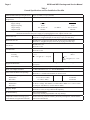
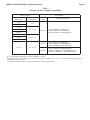
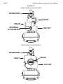
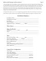
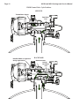
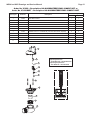
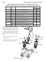
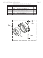
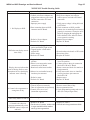
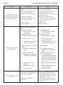
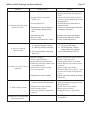
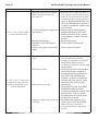
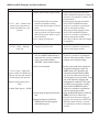
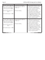
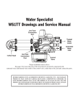
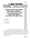
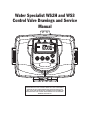
Water Specialist WS2H and WS3
Control Valve Drawings and Service
Manual
HYDROCARBONS SUCH AS KEROSENE, BENZENE, GASOLINE, ETC., MAY
DAMAGE PRODUCTS THAT CONTAIN O-RINGS OR PLASTIC COMPONENTS.
EXPOSURE TO SUCH HYDROCARBONS MAY CAUSE THE PRODUCTS TO
LEAK. DO NOT USE THE PRODUCT(S) CONTAINED IN THIS DOCUMENT ON
WATER SUPPLIES THAT CONTAIN HYDROCARBONS SUCH AS KEROSENE,
BENZENE, GASOLINE, ETC.
Page 2
WS2H and WS3 Drawings and Service Manual
WS2H and WS3 Drawings and Service Manual
Table of Contents
General Specifications and Pre-Installation Checklist ......................................................4
Software and Power Supply Compatibility .......................................................................5
Installation Instructions .....................................................................................................6
Installation Summary ........................................................................................................9
WS2H Control Valve Cycle Positions ............................................................................10
WS3 Control Valve Cycle Positions ...............................................................................13
Front Cover and Drive Assembly ...................................................................................16
WS2H Drive Cap Asy, Downflow Piston, Regenerant Piston, Spacer Stack Asy,
Drive Back Plate and Main Body, and Meter .................................................................17
WS3 Drive Cap Asy, Downflow Piston, Regenerant Piston, Spacer Stack Asy,
Drive Back Plate, Main Body .........................................................................................18
V3075 and V3075BSPT WS3 3” Meter Assembly..........................................................19
Brine Valve Body and Injector Components....................................................................20
Base Tank Adapters .........................................................................................................21
V3158-04 2” Drain Elbow ¾” Male NPT without silencer ............................................22
V3008-05 2” Drain Fitting 1” Straight Male NPT without silencer ...............................23
V3079 and V3080 NPT and BSPT 1” and 1.5” DLFC ...................................................24
V3051 and V3051 BSPT 2” DLFC ................................................................................25
V3764 and V3764BSPT 3” DLFC ASY .........................................................................26
V3063 and V3063BSPT 2” Motorized Alternating Valve ..............................................27
V3076 and V3076BSPT 2” Motorized Alternating Valve Rev2......................................28
V3098 and V3098BSPT 2” No Hard Water Bypass MxF ...............................................29
V3083 and V3083BSPT 3” Motorized Alternating Valve ..............................................30
V3099 and V3099BSPT 3” No Hard Water Bypass MxF ...............................................31
V3060 and V3060BSPT 2H Bypass Valve Auto and Manual .........................................32
V3053 WS2H 2.5” Groove Lock Clamp ........................................................................33
Error Codes .....................................................................................................................34
Trouble Shooting Guide ..................................................................................................35
Standard Injector Graphs ................................................................................................43
Page 3
Page 4
WS2H and WS3 Drawings and Service Manual
Table 1
General Specifications and Pre-Installation Checklist
Minimum/Maximum Operating Pressures
20 psi (138 kPa) -125 psi (862 kPa)
Minimum/Maximum Operating
Temperatures
40°F (4°C) – 110°F (43°C)
Power Adapter:
Supply Voltage
Supply Frequency
Output Voltage
Output Current
U.S.
120V AC
60 Hz
20V or 24V AC
800 mA
International
230V AC
50 Hz
20V or 24V AC
1000 mA
see Table 2
No user serviceable parts are on the PC board, the motor, or the Power adapter. The means of
disconnection from the main power supply is by unplugging the Power adapter from the wall.
Service flow rate
WS2H Valve: 125 gpm (473 lpm, 28.4 m3/h) @ 15 psig (103 kPa) drop
WS3 Valve: 250 gpm (946 lpm, 56.8 m3/h) @ 15 psig (103 kPa) drop
Backwash flow rate
WS2H Valve: 125 gpm (473 lpm, 28.4 m3/h) @ 25 psig (172 kPa) drop
WS3 Valve: 220 gpm (833 lpm, 50.0 m3/h) @ 25 psig (172 kPa) drop
CV Service
WS2H Valve: 32.3
WS3 Valve: 64.6
CV Backwash
WS2H Valve: 25.0
WS3 Valve: 44.0
Meter:
Accuracy
Flow Range
WS2H Valve: Internal Meter
+5%
1.5 – 125 gpm (5.7 – 473 lpm)
WS3 Valve: Optional External
Meter
+5%
3.5 – 350 gpm (13.3 – 1325
lpm)
Regenerant Refill Rate
WS2H and WS3 Valves: Variable - Shipped from Factory with 2.2 gpm
(8.33 lpm)
Injectors
WS2H & WS3 Valves: See Injector Graphs V3010-2A through 2H
Brine Line Adapters Included
1” Male NPT Elbow & ¾” x 1” Solvent Weld Elbow
Inlet, Outlet and Drain Line Openings
WS2H Valve: 2” Female NPT or BSPT or 2.5” Groove Lock
WS3 Valve: 3” Female NPT or BSPT, No Groove Lock
Distributor Tube Opening:
WS2H Valve
WS3 Valve
Tank Connection:
WS2H Valve
WS3 Valve
Female NPT Inlet & Outlet
2.375” OD (2.0” NPS)
3.5” OD (3” NPS)
Female BSPT Inlet & Outlet
63 mm OD
90 mm OD
4”-8UN, 6” Flange, Side Mount (2” Female NPT or BSPT or 2.5” Groove Lock)
6” Flange or Side Mount (3” Female NPT or BSPT)
Shipping Weight
WS2H Valve with Meter: 50 lbs (22.7 kg)
WS3 Valve: 57 lbs (25.9 kg) Meter Sold Separately
PC Board Memory
Nonvolatile EEPROM
(electrically erasable programmable read only memory)
Compatible with the following typical
concentrations of regenerants/chemicals
Sodium chloride, potassium chloride, potassium permanganate, sodium bisulfite,
chlorine and chloramines
WS2H and WS3 Drawings and Service Manual
Page 5
Table 2
Software and Power Supply Compatibility
Software Version
V3242-01BOARD
Main Board1
114.10
114.11
Power Supply
V3243-01BOARD
System Board
Output
Voltage
Part # and Description
1.03
115.17
115.25
1.07 or 1.08
200.01
24 VAC
V34612 WS2H/3 AC ADAPTER
V3461EU WS2H/3 AC ADAPTER EU
V3461UK WS2H/3 AC ADAPTER UK
24 VAC
V34612 WS2H/3 AC ADAPTER
V3461EU WS2H/3 AC ADAPTER EU
V3461UK WS2H/3 AC ADAPTER UK
20 VAC3
V3461-01 WS2H/3 AC ADAPTER 20V
V3461EU-01 WS2H/3 AC ADAPTER EU 20V
V3461UK-01 WS2H/3 AC ADAPTER UK 20V
215.02
215.03
1.11 or 1.13
215.04
215.10
1
1.11 or 1.13
It is recommended to maintain one version throughout a system.
Replacement V3461 power supplies have screw terminals and are shipped less a cord. Use cord from existing power supply to
connect to the screw terminals.
3
V3461EU-01 and V3461UK-01 will not be available for sale until August 2010.
2
Page 6
WS2H and WS3 Drawings and Service Manual
Installation:
WS2H CONTROL VALVE TOP VIEW
BRINE/REFILL
INLET
DRAIN
INTERNAL
FLOW METER
OUTLET
WS3 CONTROL VALVE TOP VIEW
BRINE/REFILL
INLET
DRAIN
OUTLET
WS2H and WS3 Drawings and Service Manual
Page 7
DISTRIBUTOR PIPE HEIGHT:
Recommended distributor pipe height for top mounted WS2H Control valves is 2 ¼” – 2 ½” above the top of tank for fiberglass
tanks. Please verify distributor pipe and pilot o-ring engagement and make proper allowances for tank expansion.
Recommended distributor pipe height for top mounted WS3 Control valves is 2 ½” – 2 ¾” above the top of tank for fiberglass tanks.
Please verify distributor pipe and pilot o-ring engagement and make proper allowances for tank expansion.
GENERAL INSTALLATION & SERVICE WARNINGS
The control valve and fittings are not designed to support the weight of the system or the plumbing.
Do not use Vaseline, oils, other hydrocarbon lubricants or spray silicone anywhere. A silicone lubricant may be used on black
o-rings but is not necessary.
HYDROCARBONS SUCH AS KEROSENE, BENZENE, GASOLINE, ETC., MAY DAMAGE PRODUCTS THAT
CONTAIN O-RINGS OR PLASTIC COMPONENTS. EXPOSURE TO SUCH HYDROCARBONS MAY CAUSE THE
PRODUCTS TO LEAK. DO NOT USE THE PRODUCT(S) CONTAINED IN THIS DOCUMENT ON WATER SUPPLIES
THAT CONTAIN HYDROCARBONS SUCH AS KEROSENE, BENZENE, GASOLINE, ETC.
THIS WATER METER SHOULD NOT BE USED AS THE PRIMARY MONITORING DEVICE FOR CRITICAL OR
HEALTH EFFECT APPLICATIONS
Do not use pipe dope or other sealants on threads. Teflon tape is recommended to be used on all threads.
Use of pipe dope may break down the plastics in the control valve.
When servicing the valve, water may leak from
the valve. Water from the valve may create a slip
hazard. Clean up water spills.
Disconnect from electrical power prior to
servicing the valve.
Allow two feet of clearance to service WS2H and WS3 valves.
The valve will withstand transportation and storage temperatures of -13 ˚F (-25 ˚C) to 131 ˚F (55 ˚C) and for short periods up to 158
˚F (70 ˚C). If valve has been exposed to freezing conditions let valve warm up to room temperature before running water through it.
The valve has been packaged to prevent damage from the effects of normal humidity, vibration and shock.
SITE REQUIREMENTS:
• The plug-in Power adapter is for dry locations only
• The tanks should be on a firm, level surface
• Electrical: Use an uninterrupted outlet installed within 15 feet (4.57 meters) of the water conditioner.
All plumbing should be done in accordance with local codes.
1. Locate the water conditioner so the distance between the drain and the water conditioner is as short as possible.
2. Regenerant tanks that must be refilled should be located where they are easily accessible. It is recommended a safety brine valve
be used.
3. Do not install any water conditioner with less than 10 feet of piping between its outlet and the inlet of a water heater.
4. Do not locate unit where it or its connections (including the drain and overflow lines) will ever be subjected to room temperatures
under 40° F (4° C).
5. The use of resin cleaners in a non-vented enclosure is not recommended.
Page 8
WS2H and WS3 Drawings and Service Manual
6. INLET/OUTLET PLUMBING: Connect to a supply line downstream of outdoor spigots. Install inlet and
outlet shutoff valves for the control valve; see top view drawings for control valve inlet and outlet locations.
Installation of a three valve bypass is recommended. If using plastic fittings ground the water conditioner
per local electric codes. If an external water meter is used, install the water meter on the outlet side of the
control valve. It is recommended that the meter assembly be installed horizontally or in a downflow vertical
position to reduce turbine bearing wear. The turbine assembly may be orientated in any direction. Remove
the cover and drive bracket and thread the water meter cord through the hole in the back plate. Reinstall the
drive bracket. Weave the cord through the strain relief on the backplate and connect the end to the three prong
connector labeled FLOW on the printed circuit board. Re-install the cover.
7. Drain: Verify that the drain can handle the backwash rate of the water conditioner. Correctly size the drain
line and install an appropriately sized drain line flow control. For WS2H and WS3 valves a drain line flow
control are NOT supplied with a valve. For WS2H valves the drain outlet is 2” Female NPT or BSPT threads
or 2.5” groove lock connection. For WS3 valves the drain port is 3” Female NPT or BSPT, no groove lock
connection. If using copper, solder joints near the drain must be done prior to connecting the drain line flow
control fitting. Leave at least 6” (152.4 mm) between the drain line flow control fitting and solder joints to
prevent heat from damaging the flow control. Avoid elevating the drain line above the control valve where
possible. Discharge the drain line through an air gap to a receptacle in accordance with local plumbing codes.
IMPORTANT: Never insert a drain line directly into a drain, sewer line, or trap. Always allow an air
gap between the drain line and the receptacle to prevent back siphonage.
8. Regeneration: If the control valve is to be used to regenerate the water conditioner with brine (saturated
salt solution) or other regenerants. The WS2H and WS3 control valves regenerant port has a 1” 90° Male NPT
threaded outlet connection that swivels 360°. To ensure acceptable operation of the injectors use 1” pipe to
connect to the brine tank. Smaller drain line flow controls may result in the injector performance not matching
the injector graphs. Use an adequately size drain line flow control to ensure proper brine draw.
See Table 3 for injector order number and size for tank diameter. An overflow drain line from the regenerant
tank that discharges into an acceptable drain is recommended, as a regenerant overflow could damage
furnishings or the building structure. Connect a line to the overflow fitting on the regenerant tank. If an
overflow fitting is not already installed on the regenerant tank, install one. Do not elevate the overflow drain
line. Discharge the overflow drain line through an air gap to a receptacle in accordance with local plumbing
codes.
Table 3
WS2H and WS3 Valve Injector Order Information
Injector Order Number
Typical Tank Diameter4
V3010-2A
18”
V3010-2B
21”
V3010-2C
24”
V3010-2D
30”
V3010-2E
36”
V3010-2F
42”
V3010-2G
48”
V3010-2H
63”
All injector graphs are at the end of this manual for total, slow rinse and draw flow rates.
4
Actual injector size used may vary depending on the design and application of the system. Injectors in table are sized for a typical
downflow softener using standard mesh synthetic cation exchange media regenerating with sodium chloride.
WS2H and WS3 Drawings and Service Manual
Page 9
9. Power Adapter: If a Power Adapter is already connected to the control valve, plug the Power Adapter into
an uninterrupted outlet. If the Power Adapter cord has not yet been connected to the control valve, remove the
control valve cover and the drive bracket and thread Power Adapter cord through the hole in the back plate.
Reinstall the drive bracket. Weave the cord through the strain relief on the backplate and connect the end
to the four pin connector on the printed circuit board labeled POWER. Reinstall the cover. Plug the Power
Adapter into an uninterrupted outlet.
10. Program the control valve: It is very important to program the control valve for the type of system (e.g.
water softener of filter) and the end use application. Check the program used prior to testing the system.
Installation Summary
Installation Date: ___________________________________________
Installation Location: _______________________________________
Installer(s): _______________________________________________
Phone Number: ____________________________________________
Application Type: (Softener) _______ Other: ____________________
Water Source: ____________________________________________
Water Test Results:
Hardness:___________ Iron: ___________pH:___________________
Other: ___________________________________________________
_________________________________________________________
Misc:
Service Flow Rates: min. _________ max. ___________
Tank Size: Diameter _________ Height: ______________
Resin or Media Volume: ___________________________
Resin or Media Type: _____________________________
Capacity: _______________________________________
Salt or Fill Setting per Regeneration: _________________
Brine Tank Size: _________________________________
Control Valve Configuration:
Valve Type: _____________________________________
Valve Part Number: _______________________________
Valve Serial Number: _____________________________
Regenerant Refill Control: _________________ gpm/lpm
Injector Size: ____________________________________
Drain Line Flow Control: __________________ gpm/lpm
Page 10
WS2H and WS3 Drawings and Service Manual
WS2H Control Valve Cycle Positions
SERVICE
Treated Water Supply
Raw Water
Inlet
BACKWASH
Raw/Hard Water is bypassed
during regeneration
Backwash water
to drain
Raw Water
Inlet
WS2H and WS3 Drawings and Service Manual
Page 11
DRAW
Raw/Hard Water is bypassed
during regeneration
Regenerant water
to drain
Raw Water
Inlet
Regenerant
solution being
drawn in
Injector feed
water from Raw
Water Inlet
supply
SLOW RINSE
Raw/Hard Water is bypassed
during regeneration
Slow Rinse water
to drain
Raw Water
Inlet
Injector feed
water from
raw water inlet
supply
Page 12
WS2H and WS3 Drawings and Service Manual
RINSE
Treated Water Supply
Rinse water
to drain
Raw Water
Inlet
SOFT WATER REFILL
Raw/Hard Water is bypassed
during regeneration
Raw Water
Inlet
Treated Water to
Regenerant Tank
Treated water
from Refill Tube
Refill port to refill
tube for treated water
WS2H and WS3 Drawings and Service Manual
Page 13
WS3 Control Valve Cycle Positions
SERVICE
Raw Water
Inlet
Treated Water Outlet
BACKWASH
Backwash Water
to Drain
Raw/Hard Water is bypassed
during regeneration
Raw Water
Inlet
Page 14
WS2H and WS3 Drawings and Service Manual
DRAW
Backwash Water
to Drain
Raw/Hard Water is bypassed
during regeneration
Raw Water
Inlet
Regenerant
solution being
drawn in
Injector feed
water from Raw
Water Inlet
supply
SLOW RINSE
Raw/Hard Water is bypassed
during regeneration
Slow Rinse Water
to Drain
Raw Water
Inlet
Injector feed
water from Raw
Water Inlet
supply
WS2H and WS3 Drawings and Service Manual
Page 15
RINSE
Rinse Water to
Drain
Raw/Hard Water is bypassed
during regeneration
Raw Water
Inlet
SOFT WATER REFILL
Treated Water Supply
Raw Water
Inlet
Treated Water to
Regenerant Tank
Treated water
from Refill Tube
Refill port to refill
tube for treated water
Page 16
WS2H and WS3 Drawings and Service Manual
Front Cover and Drive Assembly
Drawing No.
Order No.
Description
Quantity
1
V3068
WS2H/3 POD FRNT-BK COVERS
1a
V3082
WS2H/3 POD ASY COMPLETE W/BOARD*
2
V3241-01 BOARD
WS2H/3 PC BOARD DISPLAY
1
3
V3248
WS2H/3 CABLE DISPLAY POD
1
4
V3242-01BOARD
WS2H/3 PC BOARD VALVE
1
5
V3224-01R
WS2H/3 COVER ASY PLATINUM
1
6
V3107-01
WS1 MOTOR ASY
1
7
V3226-01
WS2H/3 DRIVE BRACKET ASY
1
8
V3110
WS1 DRIVE GEAR 12X36
3
9
V3109
WS1 DRIVE GEAR COVER
1
V3461
WS2H/3 AC ADAPTER (shipped less cord)
1
V3461EU
WS2H/3 AC ADAPTER EU
V3461UK
WS2H/3 AC ADAPTER UK
V3461-01
WS2H/3 AC ADAPTER 20VAC
V3461EU-01
WS2H/3 AC ADAPTER EU 20VAC
V3461UK-01
WS2H/3 AC ADAPTER UK 20VAC
V3243-01BOARD
WS2H/3 PC BOARD SYSTEM
Optional
Not Shown
V3475-12
WS2H/3 SYS CONNECT CORD 12 FT RED
Optional
Not Shown
V3475-24
WS2H/3 SYS CONNECT CORD 24 FT BL
Optional
Not Shown
V3475-36
WS2H/3 SYS CONNECT CORD 36 FT YEL
Optional
Not Shown
10
1
Optional
See Table 2
Software and
Power Supply
Compatibility
for option
selection
*Contains items 1,2 & 3 Pod Assembly, PC Board and Cable
1a
5
1
7
9
8
2
3
4
6
10
WS2H and WS3 Drawings and Service Manual
Page 17
WS2H Drive Cap Assembly, Downflow Piston, Regenerant Piston, Spacer Stack Assembly,
Drive Back Plate, Main Body and Meter
Drawing No.
Order No.
1
V3275
2
3
4
5
6
7
8
V3291
V3225
V3066
V3289
V3204-01
V3238-01***
V3065
V3468
V3465
V3201-03
V3201BSPT-03
V3632*
V3003-02
V3118-03
V3105
V3501
V3279
V3280
V3452
V3054**
V3276
V3269
D1300-01
Not Shown
9
10
11
12
13
14
15
16
17
18
19
Not Shown
Description
Quantity
WS2H/3 SCREW BTNSKT HD SS3/8-16X2-1/4
(7/32” hex allen wrench required)
WS2H/3 WASHER SS 3/8
WS2H/3 BACK PLATE
WS2H DRIVE ASY
O-RING 344
WS2H PISTON
WS2H/3 BRINE PISTON
WS2H STACK ASY
WS2H/3 PLUG 1/4 HEX NPT (included when ordering V3201-03)
WS2H/3 PLUG 1/4 HEX BSPT (included when ordering V3201BSPT-03)
WS2H BODY W/V3468 PLUG
WS2H BSPT BODY W/V3465 PLUG
WS1.5/2/3 METER RETAINING CLIP
WS1.5/2H METER COMMERCIAL ASY
WS1.5/2 TURBINE ASY
O-RING 215
WS1.5/2 TURBINE CLIP
O-RING 346
O-RING 332 FOR VALVE BODIES WITH NPT THREADS
O-RING 230 FOR VALVE BODIES WITH BSPT THREADS
WS2H 4 IN BASE CLAMP ASY
WS2H/3 BOLT HEX SS 5/16-18X1-3/4
WS2H/3 NUT 5/16-18 SS HEX
TOP BAFFLE DFSR CLACK 2/63MM
4
4
1
1
1
1
1
1
2
1
1
1
1
1
1
1
1
1
1
1
1
* In 2008 a modification was made to Meter Housings to use V3632 WS1.5/2/3 Meter Retaining Clip. Do not use V3632 on old style housings which have holes through the castings to
accept the U-shaped V3223 WS2 Meter Clip.
**V3054 WS2 4 IN BASE CLAMP ASY includes a V3276 WS2 BOLT HEX SS 5/16-18X1-3/4 and V3269 WS2 NUT 5/16-18 SS HEX.
***V3238-01 Brine Piston is used for Backwash Only valves.
THIS WATER METER SHOULD NOT BE USED AS THE PRIMARY MONITORING DEVICE FOR CRITICAL OR HEALTH EFFECT APPLICATIONS.
Service or replace the turbine by:
1. Turn the bypass for the system off and relieve the pressure on the system.
2. Press downward on the remote meter assembly to relieve tension on the retaining clip V3632 (or the U-shaped V3223 WS2 Meter Clip). Remove the clip and take
the meter assembly out of the housing.
3. Remove the bend from the two exposed tips of the retaining clip V3501 and remove clip.
4. Service or replace the V3118-03 WS15/2 Turbine Assembly and place it back in the turbine shaft.
5. Insert the V3501 WS15/2 Turbine Clip and re-bend the exposed ends of the clip. The V3118-03 turbine has a groove to line up with the V3501 WS15/2 Turbine Clip.
6. Insert meter assembly back into the meter housing.
7. Re-install the meter retaining clip V3632 as shown below (or the U-shaped V3223 WS2 Meter Clip).
8. Open the bypass for the system slowly to bring back into service and check to be sure you have no water leaks.
10
B or indent
indicates BSPT
11
N or no mark
indicates NPT
Typical meter retaining clip installation.
Ensure clip is fully engaged in groove
and tabs positioned in slot as shown.
12
14
13
9
3
4
5
8
6
7
1
2
15
16
17
Install D1300-01 upper diffuser (not shown) when using the 4” Quick Dissconnect (V3064)
18
19
Page 18
WS2H and WS3 Drawings and Service Manual
WS3 Drive Cap Assembly, Downflow Piston, Regenerant Piston, Spacer Stack Assembly,
Drive Back Plate and Main Body
Drawing No.
1
2
3
4
5
6
7
8
Not Shown
9
10
11
12
13
14
Not Shown
Order No.
V3274
V3291
V3225
V3093
V3289
V3666-01
V3238-01**
V3092
V3468
V3465
V3667-03
V3667BSPT-03
V3763
V3762
V3091*
V3276
V3269
V3672
Description
WS2H/3 SCREW BTNSKT HD SS3/8-16X2
(7/32” hex allen wrench required)
WS2H/3 WASHER SS 3/8
WS2H/3 BACK PLATE
WS3 DRIVE ASY
O-RING 344
WS3 PISTON
WS2H/3 BRINE PISTON
WS3 STACK ASY
WS2H/3 PLUG 1/4 HEX NPT (included when ordering V3667-03)
WS2H/3 PLUG 1/4 HEX BSPT (included when ordering V3667BSPT-03)
WS3 BODY W/V3468 PLUG
WS3 BSPT BODY W/V3465 PLUG
O-RING 361
O-RING 341 FOR VALVE BODIES WITH NPT OR BSPT THREADS
WS3 BASE CLAMP ASY
WS2H/3 BOLT HEX SS 5/16-18X1-3/4
WS2H/3 NUT 5/16-18 SS HEX
TOP BAFFLE DFSR CLACK 3/90MM
Quantity
4
4
1
1
1
1
1
1
2
1
1
1
1
1
1
1
*V3091 WS3 BASE CLAMP ASY includes a V3276 WS2H/3 BOLT HEX SS 5/16-18X1-3/4 and V3269 WS2H/3 NUT 5/16-18 SS HEX.
**V3238-01 Brine Piston is used for Backwash Only valves.
B Indicates BSPT
N Indicates NPT
9
3
4
5
8
6
7
1
2
10
11
14
Install V3672 upper diffuser (not shown) when using the 6” Flange Base (V3090)
12
13
WS2H and WS3 Drawings and Service Manual
Page 19
V3095 WS3 Meter NPT MxF Assembly and V3095BSPT-15 WS3 Meter BSPT MxF Assembly
V3095-15 WS3 Meter ASY NPT MxF 15FT and V3095BSPT-15 WS3 Meter ASY BSPT MxF 15FT
6
1
2
B indicates BSPT
N indicates NPT
4
Typical meter retaining clip installation.
Ensure clip is fully engaged in groove
and tabs positioned in slot as shown.
3
Service or replace the turbine by:
1. Turn the bypass for the system off and relieve the pressure on the system.
2. Press downward on the remote meter assembly to relieve tension on the retaining clip V3632.
Remove the clip and take the meter assembly out of the housing.
3. Remove the bend from the two exposed tips of the retaining clip V3501 and remove clip.
4. Service or replace the V3118-03 WS15/2 Turbine Assembly and place it back in the turbine shaft.
5. Insert the V3501 WS15/2 Turbine Clip and re-bend the exposed ends of the clip. The V3118-03
turbine has a groove to line up with the V3501 WS15/2 Turbine Clip.
6. Insert meter assembly back into the meter housing.
7. Re-install the meter retaining clip V3632 as shown above.
8. Open the bypass for the system slowly to bring back into service and check to be sure you have
no water leaks.
5
Drawing No.
Order No.
V4039
1
V3221
Description
WS3 METER COMMERCIAL ASY 4 FT CORD
(includes V3118-03, V3105 & V3501)
WS REMOTE METER ASY 15 FT CORD
(includes V3118-03, V3105 & V3501)
WS15/2 TURBINE ASY
V3095
V3095BSPT
1
1
V3095-15
V3095BSPT-15
1
1
2
V3118-03
1
1
1
1
3
V3105
O-RING 215
1
1
1
1
4
V3501
WS15/2 TURBINE CLIP
1
1
1
1
WS3 METER NPT MxF HOUSING
1
V3844-01
5
V3844BSPT-01 WS3 METER BSPT MxF HOUSING
6
V3632
Not shown
V3602
WS1.5/2/3 METER RETAINING CLIP
WS3 FLOW STRAIGHTENER
(located inside meter housing)
1
1
1
1
1
1
1
1
1
1
1
Installation
Installation of the V3075 WS3 Meter NPT Assembly can be accomplished with 3” NPT pipe. For V3075BSPT WS3 Meter BSPT Assembly use 3”
BSPT pipe. It is recommended that the meter assembly be installed horizontally or in a downflow vertical position to reduce turbine bearing wear.
WHEN INSTALLING THE METER, MAKE SURE THE ARROW ON THE METER BODY IS GOING THE SAME DIRECTION AS
THE WATER FLOW. THE METER CAN BE INSTALLED IN HORIZONTAL OR VERTICAL APPLICATIONS.
THIS WATER METER SHOULD NOT BE USED AS THE PRIMARY MONITORING DEVICE FOR CRITICAL OR HEALTH EFFECT
APPLICATIONS.
OPERATING PRESSURES: 20 PSI MINIMUM / 125 PSI MAXIMUM
OPERATING TEMPERATURES: 40°F MINIMUM / 110°F MAXIMUM
The 22 gauge wire crimp terminals are Molex Series 41572 or 40445. The housing connector is Molex Series 2695 White Housing, P/N 22-01-3037.
The housing connector diagram shows the proper installation of the RED,
WHITE and BLACK wires for CLACK CORPORATION CONTROL VALVES.
When connecting to other manufacturers control valves please contact your
original equipment manufacturer for proper wiring instructions.
RED AND WHITE LEADS
NOT INSERTED IN HOUSING
Wiring:
• The meter must be supplied with a DC voltage between 4 and 24 volts
• The RED wire is positive
• The BLACK wire is negative
• The WHITE wire is the meter output
Calibration:
• For WS2H valves select 8 pulses if valve software records in gallons and 2.1 if valve software
records in liters.
V3221 WIRE
• The calibration factor for the WS3 Meter Assembly is 8 pulses per gallon when used on
HARNESS
applications other than WS2H valves.
• The meter flow range is 3.5-350 gpm + 5% (output signal 0.46 Hz to 46.6 Hz). NOTE: Not all flow
monitors will register accurately at either the low or high flow range of this meter. Contact your
flow monitor manufacturer for limitations.
• Pressure drop at 350 gpm is 7.3 PSI
WHITE
RED
BLACK
BLACK
CLACK
CORPORATION
VALVES ONLY
Page 20
WS2H and WS3 Drawings and Service Manual
WS2H and WS3 Brine Valve Body and Injector Components
Drawing No.
1
2a
2b
3
4
5
6
7
8
9
10
11
12
13
14
15
Not Shown
16****
Not Shown
Not Shown
Order No.
V3237-01
V3236-04*
V3670-01**
V3289
V3067
V3477
V3152
V3275
V3291
V3162-022***
V3231
V3277
V3105
V3150
V3151
V3149
V3189
V3010-2A
V3010-2B
V3010-2C
V3010-2D
V3010-2E
V3010-2F
V3010-2G
V3010-2H
V3499*****
V3797******
Quantity
Description
WS2H
1
1
WS2H/3 SOFTFILL TUBE ASY
WS2H INJECTOR TUBE ASY FOR A THRU H
WS3 INJECTOR TUBE DOWNFLOW ASY
O-RING 344
WS2H/3 BRINE BODY ASY
WS2H/3 INJECTOR CAP
O-RING 135
WS2H/3 SCREW BSHD SS 3/8-16X2-1/4
(7/32” hex allen wrench required)
WS2H/3 WASHER SS 3/8
WS1 DLFC 022 FOR 3/4
WS2H/3 REFILL FLOW CNTRL RETAINER
O-RING 211
O-RING 215
WS1 SPLIT RING
WS1 NUT 1 QC
WS1 FTG 1 PVC MALE NPT ELBOW
WS1 FTG 3/4&1 PVC SLVNT 90
WS2/2H/3 INJECTOR ASY A
WS2/2H/3 INJECTOR ASY B
WS2/2H/3 INJECTOR ASY C
WS2/2H/3 INJECTOR ASY D
WS2/2H/3 INJECTOR ASY E
WS2/2H/3 INJECTOR ASY F
WS2/2H/3 INJECTOR ASY G
WS2/2H/3 INJECTOR ASY H
WS2H/3 FITTING CAP 1 IN THREADED
WS1 FTG 1 PVC MALE BSPT ELBOW
Backwash Only
14
V3499 Cap
installed from
factory.
Proper RFC orientation
directs refill water flow
towards the washer face
with radius and text.
15
11
7
3
16
2a
1
4
2b
4
4
1
1
1
1
1
1
1
Optional
4
1
1
1
1
1
1
1
Optional
1
BSPT Only
1
BSPT Only
****V3010-2A through V3010-2G injectors
contain a V3283 O-RING 117 and a V3284
O-RING 114. V3010-2H injectors use a
V3283 O-RING 117 and D1263 O-RING
116.
5
Diffuser is snipped off if using
D through G injectors. Order
V3236-04 if using H injector.
4
***Any V3162-XXX flow control may be
used. V3237-01 WS2H SOFTFILL TUBE
ASY contains a V3155 O-RING 112, V3287
O-RING 110 and a V3288 O-RING 206.
8
9
***V3236-01. Could be used
“as is” with A-C injectors.
1
1
1
1
1
**V3670-01 WS3 INJECTOR TUBE
DOWNFLOW ASY contains a V3285
O-RING 213, V3286 O-RING 216 and a
V3163 O-RING 019.
12
10
1
1
1
1
*V3236-04 WS2H INJECTOR TUBE ASY A
thru H contains a V3285 O-RING 213 and a
V3286 O-RING 216.
13
WATER
FLOW
WS3
1
6
Backwash Only Valves include a V3499 but
do not include the following parts: V3189,
V3162-022, V3231 and V3277.
***** Install V3499 on V3149 if valve is to
be set up as a backwash only valve.
****** BSPT valves also include a V3797
WS1 FTG 1 PVC MALE BSPT ELBOW
WS2H and WS3 Drawings and Service Manual
Page 21
V3064 WS2H/2QC 4 INCH BASE ASY (For use on WS2H or WS2QC only)
Drawing No. Order No.
1
V3202-01
2
V3419
1
Description
WS2H BASE
O-RING 347
Quantity
1
1
2
V3055 WS2H/2QC 6 INCH FLANGE BASE ASY or V3090 WS3 6 INCH FLANGE BASE ASY
Quantity
V3055 V3090
V3444
WS2H SCREW HEXCAP 5/16-18X2 SS
12
12
V3293
WS2H WASHER SS 5/16 FLAT
24
24
V3445
WS2H WASHER SPLIT LOCK 5/16 SS
12
12
V3447
WS2H NUT HEX 5/16-8 FULL SS
12
12
COR60FL O RING 6 FLANGE ADAPTER
1
1
V3261-01 WS2H FLANGE BASE
1
V3671-01 WS3 FLANGE BASE
1
Drawing
Order No.
No.
1
1
2
3
4
5
2
6
3
4
5
6
Order No.
Description
Description
Inlet/Outlet
For Valve
V3260-02
WS2H/2QC SIDE MOUNT NPT
ASY
2” Female NPT or 2.5” WS2H NPT
Groove Lock
V3674-02
WS3 SIDE MOUNT NPT ASY
3” Female NPT
WS3 NPT
V3674BSPT-02
WS3 SIDE MOUNT BSPT ASY
3” Female BSPT
WS3 BSPT
V3260BSPT-02 WS2H/2QC SIDE MOUNT BASE BSPT ASY
1
Drawing No.
1
2
2
Order No.
V3280
V3260BSPT-01
Description
O-RING 332
WS2H SIDE MOUNT BASE BSPT
Quantity
1
1
When using a side mount base with 2H or 2QC BSPT valves replace
distributor pilot o-ring V3452 O-RING 230 with V3280 O-RING
332. See exploded view of 2H or 2QC valve for specific location of
distributor pilot o-ring.
Page 22
WS2H and WS3 Drawings and Service Manual
Order No. V3158-04
Description: WS2 Drain Elbow ¾” Male NPT without Silencer
DRAWING
NUMBER
1
2
4
5
ORDER
NUMBER
V3983
H4615
V3162-007
V3162-010
V3162-013
V3162-017
V3162-022
V3162-027
V3162-032
V3162-042
V3162-053
V3162-065
V3162-075
V3162-090
V3162-100
V3159-01
V3163
6
V3158-03
3
DESCRIPTION
QTY
WS2 DLFC ADAPTER
CLIP RETAINING 474/WS1
WS1 DLFC 0.7 gpm for 3/4
WS1 DLFC 1.0 gpm for 3/4
WS1 DLFC 1.3 gpm for 3/4
WS1 DLFC 1.7 gpm for 3/4
WS1 DLFC 2.2 gpm for 3/4
WS1 DLFC 2.7 gpm for 3/4
WS1 DLFC 3.2 gpm for 3/4
WS1 DLFC 4.2 gpm for 3/4
WS1 DLFC 5.3 gpm for 3/4
WS1 DLFC 6.5 gpm for 3/4
WS1 DLFC 7.5 gpm for 3/4
WS1 DLFC 9.0 gpm for 3/4
WS1 DLFC 10 gpm for 3/4
WS1 DLFC RETAINER ASY
O-RING 019
WS1 DRN ELBOW 3/4 MALE
NO HOLE
1
1
ONE
DLFC
MUST BE
USED IF
¾”
FITTING
IS USED.
1
1
1
This assembly is shipped without drain line flow control (DLFC) – install DLFC
before using. Use a minimum drain line size of ¾”.
Apply
Teflon Tape
6
5
Water flow
Proper DLFC orientation
directs water flow toward
the washer face with
rounded edge.
Lubricate o-rings with
silicone.
Order DLFC separately
4
2
3
1
Apply
Teflon
Tape
WS2H and WS3 Drawings and Service Manual
Page 23
Order No. V3008-05
Description: WS2 Drain Fitting 1” Male NPT Straight without Silencer
DRAWING
NUMBER
ORDER
NUMBER
DESCRIPTION
QTY
1
V3166-01
WS1 FTG FLOW CONTROL BODY
1
2
3
4
5
6
10
V3649
WS1 DRAIN FTG ADAPTER 1
O-RING 019
WS1 SPLIT RING
WS1 NUT 1” QC
O-RING 215
WS1 DLFC 9.0 GPM FOR 1
WS1 DLFC 10.0 GPM FOR 1
WS1 DLFC 11.0 GPM FOR 1
WS1 DLFC 13.0 GPM FOR 1
WS1 DLFC 15.0 GPM FOR 1
WS1 DLFC 17.0 GPM FOR 1
WS1 DLFC 20.0 GPM FOR 1
WS1 DLFC 25.0 GPM FOR 1
CLIP RETAINING
WS1.5 DLFC ADAPTER
BUSHING PVC SCH 80
1.5 TO 1.25 NPT
1
1
1
1
1
8
9
V3167
V3163
V3150
V3151
V3105
V3190-090
V3190-100
V3190-110
V3190-130
V3190-150
V3190-170
V3190-200
V3190-250
H4615
V3414
7*
* Order DLFC separately.
$SSO\
7HÀRQ7DSH
1
:DWHUÀRZ
7
6
3URSHU'/)&RULHQWDWLRQ
GLUHFWVZDWHUÀRZWRZDUG
WKHZDVKHUIDFHZLWK
URXQGHGHGJH
4
/XEULFDWHRULQJVZLWK
VLOLFRQH
5
2UGHU'/)&VHSDUDWHO\
2
3
$SSO\
7HÀRQ
7DSH
8
9
ONE
DLFC
MUST BE
USED IF
1”
FITTING
IS USED.
1
1
1
Page 24
WS2H and WS3 Drawings and Service Manual
V3079 WS DLFC ASY 125 MNPT/15 FNPT, V3079BSPT WS DLFC ASY 125 MNPT/15 FBSPT,
V3080 WS DLFC ASY 15 MNPT/15 FNPT and V3080BSPT WS DLFC ASY 15 MNPT/15 FBSPT
Drawing
No.
Order No.
1
2
3
4
5
6
Not Shown
V3081
V3645
V3645BSPT
V3646
V3388
V3652
V3441
V3162-007
V3162-010
V3162-013
V3162-017
V3162-022
V3162-027
V3162-032
V3162-042
V3162-053
V3162-065
V3162-075
V3162-090
V3162-100
V3190-090
V3190-100
V3190-110
V3190-130
V3190-150
V3190-170
V3190-200
V3190-250
Description
Quantity
V3079BSPT
V3080
1
1
1
1
1
1
4
4
1
1
V3079
1
1
WS15 RETAINER DLFC ASY
WS15 DLFC FLANGE OUTLET FNPT
WS15 DLFC FLANGE OUTLET FBSPT
WS15 DLFC FLANGE INLET MNPT
WS125 DLFC FLANGE INLET MNPT
BOLT HEXHD S/S HCS 5/16-18x3/4
O-RING 226
WS1 DLFC 0.7 gpm for 3/4
WS1 DLFC 1.0 gpm for 3/4
WS1 DLFC 1.3 gpm for 3/4
WS1 DLFC 1.7 gpm for 3/4
WS1 DLFC 2.2 gpm for 3/4
WS1 DLFC 2.7 gpm for 3/4
WS1 DLFC 3.2 gpm for 3/4
WS1 DLFC 4.2 gpm for 3/4
WS1 DLFC 5.3 gpm for 3/4
WS1 DLFC 6.5 gpm for 3/4
WS1 DLFC 7.5 gpm for 3/4
WS1 DLFC 9.0 gpm for 3/4
WS1 DLFC 10.0 gpm for 3/4
WS1 DLFC 09.0 gpm for 1
WS1 DLFC 10.0 gpm for 1
WS1 DLFC 11.0 gpm for 1
WS1 DLFC 13.0 gpm for 1
WS1 DLFC 15.0 gpm for 1
WS1 DLFC 17.0 gpm for 1
WS1 DLFC 20.0 gpm for 1
WS1 DLFC 25.0 gpm for 1
1
4
1
V3080BSPT
1
1
1
4
1
Install at least one V3190-XXX in center hole.
Knock out plugs allow installation of up to 6 more
of V3162-XXX.
Assemblies are shipped without drain line flow control (DLFC). Assembly instructions:
1. Determine the desired flow rate. Select one V3190-XXX for the center hole and a combination of V3162-XXX to arrive at the desired flow rate.
At least one V3190-XXX must be used and up to six of the V3162-XXX may be used.
2. Using a drill or punch remove the desired knockout(s) in V3081.
3. Smooth holes.
4. Install appropriate size(s) of drain line flow control washers. Play close attention to proper DLFC orientation.
5. Fit V3441 o-ring onto V3081 Retainer DLFC Asy and assemble. Properly orientate the V3081 in direction of flow.
6. Inlet threads for 1.25” female are NPT. Inlet threads for 1.5” male are NPT. Outlet threads for 1.5” are either female NPT or BSPT. 1.5” female outlet
is stamped with N or B to indicate NPT or BSPT.
5
2
Washer
h
Radius
6
w
on
cti
of
Flo
re
Di
1
4
3
DLFC not supplied.
At least one V3190-XXX
must be installed in
center hole.
Plugs may be knocked out
low
fF
or drilled to use up to six
no
tio
V3162-XXX.
c
e
Dir
B indictates BSPT
N indicates NPT
WS2H and WS3 Drawings and Service Manual
Page 25
V3051 WS2 DLFC ASY NPT and V3051BSPT WS2 DLFC ASY BSPT
Drawing No.
1
2
Order No.
Description
Quantity
V3052
WS2 DLFC Retainer ASY
V3245
WS2 DLFC FLANGE INLET NPT
1
V3245BSPT
WS2 DLFC FLANGE INLET BSPT
1
V3246
WS2 DLFC FLANGE OUTLET NPT
V3246BSPT
WS2 DLFC FLANGE OUTLET BSPT
4
V3273
BOLT HEX HD S/S HCS 3/8-16X3/4
4
5
V3278
O-ring 338
1
V3162-007
WS1 DLFC 0.7 gpm for 3/4
V3162-010
WS1 DLFC 1.0 gpm for 3/4
V3162-013
WS1 DLFC 1.3 gpm for 3/4
V3162-017
WS1 DLFC 1.7 gpm for 3/4
V3162-022
WS1 DLFC 2.2 gpm for 3/4
V3162-027
WS1 DLFC 2.7 gpm for ¾
V3162-032
WS1 DLFC 3.2 f gpm or 3/4
V3162-042
WS1 DLFC 4.2 gpm for 3/4
V3162-053
WS1 DLFC 5.3 gpm for 3/4
V3162-065
WS1 DLFC 6.5 gpm for 3/4
V3162-075
WS1 DLFC 7.5 gpm for 3/4
V3162-090
WS1 DLFC 9.0 gpm for 3/4
V3162-100
WS1 DLFC 10.0 gpm for 3/4
V3190-090
WS1 DLFC 9.0 gpm for 1
3
Not Shown
V3190-100
WS1 DLFC 10.0 gpm for 1
V3190-110
WS1 DLFC 11.0 gpm for 1
V3190-130
WS1 DLFC 13.0 gpm for 1
V3190-150
WS1 DLFC 15.0 gpm for 1
V3190-170
WS1 DLFC 17.0 gpm for 1
V3190-200
WS1 DLFC 20.0 gpm for 1
V3190-250
WS1 DLFC 25.0 gpm for 1
1
Install One or
More DLFC’s.
Up to 5 of
the V3162XXX may be
installed in the
small holes.
Up to 4 of
the V3190XXX may be
installed in the
large holes.
Assemblies are shipped without drain line flow control (DLFC). Assembly instructions:
1. Determine the desired flowrate. Select a combination of V3162-XXX’s and V3190-XXX’s to arrive at the desired flow rate. Up to five of the
smaller V3162-XXX’s may be used. Up to four of the larger V3190-XXX’s may be used.
2. Using a drill or punch remove the desired knockout(s) in V3052.
3. Smooth hole(s).
4. Install appropriate size(s) of drain line flow control washers. Pay close attention to proper DLFC orientation.
5. Assemble. Properly orientate the V3052 in the direction of flow.
4
6. Inlet and outlet threads are 2”. Couplings for iron pipe may also be used.
3
e
B indictates BSPT
N indicates NPT
w
5
4
1
2
1
Washer
Radius
Direction
Of Flow
Direction
Of Flow
Page 26
WS2H and WS3 Drawings and Service Manual
V3764 WS3 DLFC NPT ASY or V3764BSPT WS3 DLFC BSPT ASY
Drawing
No.
Order No.
Description
Quantity
V3190-090
WS1 DLFC 9.0 gpm for 1
V3190-100
WS1 DLFC 10.0 gpm for 1
V3190-110
WS1 DLFC 11.0 gpm for 1
V3190-130
WS1 DLFC 13.0 gpm for 1
V3190-150
WS1 DLFC 15.0 gpm for 1
V3190-170
WS1 DLFC 17.0 gpm for 1
V3190-200
WS1 DLFC 20.0 gpm for 1
V3190-250
WS1 DLFC 25.0 gpm for 1
V3765-01
WS3 DLFC HOUSING NPT
V3765BSPT-01
WS3 DLFC HOUSING BSPT
3
V3766
WS3 DLFC RETAINER
4
V3767
WS3 DLFC RETAINER COVER
5
V3768
WS3 DLFC RETAINER RING
6
V3769
O-RING 336
1
2
Install One or More DLFC washers.
DLFC washers must be purchased separately.
When using one retainer and one o-ring up to
5 DLFC washers can be used for flow rates from
9 gpm up to 125 gpm.
When using two retainers and two o-rings, 5 DLFC
washers are used in one of the retainers and up to 4 more
DLFC washers can be used in the other retainer for flow
rates from 9 gpm up to 225 gpm.
1
1 or 2
1
1
1 or 2
Interlock between two V3766’s
6
Larger hole for DLFC installation
1
V3768 retainer ring position
if two V3766 are used.
5
Positioning of V3767
into V3766
3
2
4
6
1
V3768 retainer ring position
if one V3766 is used.
B indicates BSPT
N indicates NPT
Assemblies are shipped without drain line flow control (DLFC) washers.
Assembly instructions:
1. Determine the desired flow rate. Select a combination of V3190-XXX’s to arrive at the desired flow rate.
2. Using a drill or punch remove the desired knockout(s) in V3766. Each V3766 retainer contains two types of knock
outs. The larger knockouts are removed to install a DLFC. If two V3766 retainers are needed remove the smaller
diameter knockout that lines up with the DLFC installed in the other retainer. One or two V3766 retainers may be
used. When using one V3766 retainer V3190-XXX must be installed in the center hole. When using two V3766
retainers a V3190-XXX must be installed in the center hole of one of the retainers and the center hole on the other
retainer must remain open.
3. Smooth hole(s).
4. Install appropriate size(s) of drain line flow control washers. Pay close attention to proper DLFC orientation.
5. Assemble. Each V3766 retainer must have a V3769 o-ring installed. One each of the V3767 retainer cover and V3768
retainer ring must be used whether one or two V3766 retainers are used. The positioning of the V3768 retainer ring
varies depending on the number of V3766 retainer(s) used. Properly orientate the V3766(s) in the direction of flow.
6. Properly orientate the complete assembly in the direction of flow. Inlet and outlet threads are 3”.
WS2H and WS3 Drawings and Service Manual
Page 27
V3063 MOTOR ALTERNATING VLV 2 NPT and V3063BSPT MOTOR ALTERNATING VLV 2 BSPT
Drawing No.
Order No.
Description
Quantity
1
V3056
WS1.5&2ALT/2BYPASS AUTO CVRASY
1
2
V3476
WS MOTOR ASY 8 FT
1
3
V3272
WS2 SCREW 8X1 SS HEX SELF TAP
3
4
V3262-01
WS1.5&2ALT/2BY REDUCGEARCVRASY
1
5
V3110
WS1 DRIVE REDUCING GEAR 12X36
3
6
V3264
WS2 BYPASS REDUCTION GEAR AXLE
3
7
V3292
WS2 SCREW BSHD SS 1/4-20X1-1/2
4
8
V3059
WS1.5&2ALT/2BYPAS AUTODRIVEASY
1
V3298-01
WS2 ALT VALVE BODY NPT
V3298BSPT-01
WS2 ALT VALVE BODY BSPT
V3474
WS ALT CONNECT CORD 8 FT BLK
9
Not Shown
1
3
4
5
8
9
1
•Operating Pressures:
20 PSI Minimum / 125 PSI Maximum
•Operating Temperatures:
40°F Minimum / 110°F Maximum
2
7
1
6
N - Stamp means threads are NPT
B - Stamp means threads are BSPT
Page 28
WS2H and WS3 Drawings and Service Manual
Order No. V3076 • Description: MOTOR ALT VLV 2 NPT REV2 or
Order No. V3076BSPT • Description: MOTOR ALT VLV 2 BSPT REV2
Drawing No.
Order No.
1
2
3
4
5
6
7
8
9
10
V3073
V3476
V3592
V3262-01
V3110
V3264
V3642
V3078
V3634-01
V3077
V3633-01
V3633-01BSPT
V3474
11
Not Shown
Description
MAV/NOHWBY COVER ASY
WS MOTOR ASY 8 FT
SCREW #8-1 PHPN T-25 SS
WS1.5&2ALT/2BY REDUCGEARCVRASY
WS1 DRIVE REDUCING GEAR 12X36
WS2 BYPASS REDUCTION GEAR AXLE
SCREW 1/4-20 X 1 1/4 BHSCS SS
MAV/NOHWBY 2 DRIVE ASY
MAV/NOHWBY 2 PISTON
MAV/NOHWBY 2 STACK ASY
WS2 MAV BODY NPT
WS2 MAV BODY BSPT
WS ALT CONNECT CORD 8FT BLK
1
Quantity
V3076
V3076BSPT
1
1
1
1
3
3
1
1
3
3
3
3
4
4
1
1
1
1
1
1
1
N/A
N/A
1
1
1
•Operating Pressures:
20 PSI Minimum / 125 PSI Maximum
•Operating Temperatures:
40°F Minimum / 110°F Maximum
2
3
4
5
6
7
8
Piston Orientation 2
No Hard Water Bypass Valve
Configurations.
9
Piston Orientation 1
Motorized Alternating Valve
and No Hard Water Bypass
Valve Configurations.
10
11
WS2H and WS3 Drawings and Service Manual
Page 29
Order No. V3098 • Description: NO HARDWATERBYPASS 2INMXF NPT or
Order No. V3098BSPT • Description: NO HARDWATERBYPASS 2INMXF BSPT
Drawing No.
Order No.
1
2
3
4
5
6
V3073
V3476
V3592
V3262-01
V3110
V3264
7
8
9
10
11
Not Shown
Description
V3098
1
1
3
1
3
3
MAV/NOHWBY COVER ASY
WS MOTOR ASY 8 FT
SCREW #8-1 PHPN T-25 SS
WS1.5&2ALT/2BY REDUCGEARCVRASY
WS1 DRIVE REDUCING GEAR 12X36
WS2 BYPASS REDUCTION GEAR AXLE
SCREW 1/4-20 X 1 1/4 BHSCS SS
V3642
(5/32” HEX ALLEN WRENCH REQUIRED)
V3078
MAV/NOHWBY 2 DRIVE ASY
V3634-01
MAV/NOHWBY 2 PISTON
V3887
WS2 NHWBY STACK ASY
V3828-01
WS2 NHWBY BODY M X F NPT
V3828BSPT-01 WS2 NHWBY BODY M X F BSPT
V3805
STRAIN RELIEF COVER KIT
4
4
1
1
1
1
N/A
1
1
1
N/A
1
1
1
1
•Operating Pressures:
20 PSI Minimum / 125 PSI Maximum
•Operating Temperatures:
40°F Minimum / 110°F Maximum
2
3
4
5
6
7
8
9
10
11
Piston Orientation
Quantity
V3098BSPT
1
1
3
1
3
3
Page 30
WS2H and WS3 Drawings and Service Manual
Order No. V3083 • Description: MOTOR ALT VLV 3 NPT or
Order No. V3083BSPT • Description: MOTOR ALT VLV 3 BSPT
Quantity
Drawing No.
Order No.
1
V3696
WS3 MAV COVER
2
V3476
WS MOTOR ASY 8 FT
1
1
3
V3592
SCREW #8-1 PHPN T-25 SS
3
3
4
V3262-01
WS 1.5&2ALT/2BY REDUCGEARCVRASY
1
1
5
V3110
WS1 DRIVE REDUCING GEAR 12X36
3
3
6
V3264
WS2 BYPASS REDUCTION GEAR AXLE
3
3
V3789
SCREW 3/8-16 X 1.75 BHCS SS
(7/32” hex allen wrench required)
4
4
7
8
V3085
9
V3695-01
10
11
Sold
Separately
Description
V3083
V3083BSPT
1
1
WS3 MAV DRIVE CAP ASY
1
1
WS3 MAV PISTON
1
1
V3084
WS3 MAV STACK ASY
1
1
V3693-01
WS3 MAV BODY NPT
1
N/A
N/A
1
V3693BSPT-01
WS3 MAV BODY BSPT
V3475-12
WS2H/WS3 SYSTEM CONNECTION CORD 12 FOOT RED
V3475-24
WS2H/WS3 SYSTEM CONNECTION CORD 24 FOOT BLUE
V3475-36
WS2H/WS3 SYSTEM CONNECTION CORD 36 YELLOW
1
One must be used for twin
tank operation.
•Operating Pressures:
20 PSI Minimum / 125 PSI Maximum
•Operating Temperatures:
40°F Minimum / 110°F Maximum
2
3
4
5
6
7
8
Piston Orientation 2
No Hard Water Bypass Valve
Configurations.
9
Piston Orientation 1
Motorized Alternating Valve
and No Hard Water Bypass
Valve Configurations.
10
11
WS2H and WS3 Drawings and Service Manual
Page 31
Order No. V3099 • Description: NO HARDWATERBYPASS 3INMXF NPT or
Order No. V3099BSPT • Description: NO HARDWATERBYPASS 3INMXF BSPT
Quantity
Drawing No.
Order No.
1
V3696
WS3 MAV COVER
2
V3476
WS MOTOR ASY 8 FT
1
1
3
V3592
SCREW #8-1 PHPN T-25 SS
3
3
4
V3262-01
WS 1.5&2ALT/2BY REDUCGEARCVRASY
1
1
5
V3110
WS1 DRIVE REDUCING GEAR 12X36
3
3
6
V3264
WS2 BYPASS REDUCTION GEAR AXLE
3
3
7
V3789
SCREW 3/8-16 X 1.75 BHCS SS (7/32” hex allen wrench required)
4
4
8
V3085
WS3 MAV DRIVE CAP ASY
1
1
9
V3695-01
10
V3888
11
V3830-01
V3830BSPT-01
Description
V3099
V3099BSPT
1
1
WS3 MAV PISTON
1
1
WS3 NHWBY STACK ASY
1
1
1
N/A
N/A
1
WS3 NHWBY M X F BODY NPT
WS3 NHWBY M X F BODY BSPT
1
2
3
•Operating Pressures:
20 PSI Minimum / 125 PSI Maximum
•Operating Temperatures:
40°F Minimum / 110°F Maximum
4
5
6
7
8
9
Piston Orientation
10
11
Page 32
WS2H and WS3 Drawings and Service Manual
V3060 WS2H BYPASS AUTO NPT, V3060BSPT WS2H BYPASS AUTO BSPT,
V3061BSPT WS2H BYPASS MANUAL BSPT and V3061 WS2H BYPASS MANUAL NPT
Drawing No.
Order No.
Quantity
Description
V3060
V3061
1
V3056
WS1.5&2ALT/2BYPASS AUTO CVRASY
1
N/A
2
V3476
WS MOTOR ASY 8 FT
1
N/A
3
V3272
WS2H SCREW 8X1 SS HEX SELF TAP
3
N/A
4
V3262-01
WS1.5&2ALT/2BY REDUCGEARCVRASY
1
N/A
5
V3110
WS1 DRIVE GEAR 12X36
3
N/A
6
V3264
WS2H BYPASS REDUCTION GEAR AXLE
3
N/A
7
V3292
WS2H SCREW BSHD SS 1/4-20X1-1/2
8
8
8
V3059
WS1.5&2ALT/2BYPAS AUTODRIVEASY
1
N/A
9
V3268
WS2H BYPASS COVER DOME MANUAL
1
2
10
V3058
WS2H BYPASS MANUAL DRIVE ASY
1
2
V3057
WS2H BYPASS BODY ASY NPT
V3057BSPT
WS2H BYPASS BODY ASY BSPT
1
1
V3053
WS2H 2-1/2 GROOVELOCK CLAMP ASY
2
2
11
Not Shown
Treated water is used for refill whether or
not an auto or manual bypass is installed to
either the inlet or outlet of a control valve.
The Auto Drive Assembly may be connected
to the inlet or outlet of the control valve to
achieve no hard water bypass. If the Auto
Drive Assembly is connected to the control
valve:
1
2
3
• inlet then all regeneration cycles occur
with treated water.
7
4
7
9
• outlet then all regeneration cycles except
for refill occur with untreated water.
5
6
8
10
11
B indictates BSPT
N indicates NPT
WS2H and WS3 Drawings and Service Manual
Page 33
V3053 WS2 2-1/2 GROOVELOCK CLAMP ASY
Drawing No.
1
2
3
4
5
Not Shown
Order No.
V3053
V3290
V3269
V3293
V3276
S3086
Description
WS2 2-1/2 GROOVELOCK CLAMP ASY
WS2 GROOVE LOCK SEAL 2.5
WS2H NUT 5/16-18 SS HEX
WS2H WASHER SS 5/16 FLAT
WS2H BOLT HEX SS 5/16-18X1-3/4
SILICONE LUBRICANT
Quantity
1
1
1
1
1
1
3
4
1
2
5
Page 34
WS2H and WS3 Drawings and Service Manual
WS2H/ WS3 Error Codes
Possible Errors
Code
Description
1001
No Encoder Pulses
1002
Unexpected Stall, Main Drive
1003
Run Time To Long, Main Drive
14001
Message Queue Full
15003
Run Time To Long, Bypass Drive
15010
Run Time To Short, Bypass Drive Could Not Drive Offline
15011
Run Time To Short, Bypass Drive Could Not Drive Online
16001
Communication Lost With Unit 2
16002
Communication Lost With Unit 3
16003
Communication Lost With Unit 4
16004
Regen List Full
17000
Run Time To Long, Separate Source Drive
17002
Run Time To Short, Separate Source Drive
18000
Reset Performed
18001
Power Loss
18002
Power Restored
WS2H and WS3 Drawings and Service Manual
Page 35
WS2H/ WS3 Trouble Shooting Guide
Problem
1. No Display on POD
Possible Cause
a. No power at electric outlet
b. Control valve Power Adapter not
plugged into outlet or power cord
end not connected to PC board
connection
c. Improper power supply
d. Poor connection between POD
connector and PC Board.
e. Defective Power Adapter
f. Defective PC Board
Solution
a. Repair outlet or use working outlet
b. Plug Power Adapter into outlet or
connect power cord end to PC Board
connection
c. Verify proper voltage is being delivered
to PC Board
d. Check connector on POD, possible
broken wire or terminal pin not inserted
properly in connector. Clean pins on PC
Board by plugging & unplugging the
POD connector a few times to remove
excess protective coating.
e. Replace Power Adapter
f. Replace PC Board
a. Power Adapter plugged into electric
outlet controlled by light switch
b. Tripped breaker switch and/or
2. POD does not display correct
tripped GFI
time of day
c. Power outage
d. Defective PC Board
a. Use uninterrupted outlet
a. Bypass/ isolation valve in bypass
position
b. Meter is not connected to meter
connection on PC Board
3. Display does not indicate that c. Restricted/ stalled meter turbine
water is flowing. Refer to user
instructions for how the display d. Meter wire not installed securely
indicates water is flowing
into three pin connector
e. Defective meter
f. Defective PC Board
a. Turn bypass/ isolation handles to place
in service position
b. Connect meter to three pin connection
labeled FLOW on PC Board
c. Remove meter and check for rotation or
foreign material
d. Verify meter cable wires are installed
securely into three pin connector
labeled FLOW
e. Replace meter
f. Replace PC Board
a. Power outage
b. Time of day not set correctly
c. Time of regeneration set incorrectly
d. Control valve set at “on 0”
(immediate regeneration)
a. Reset time of day.
b. Reset to correct time of day
c. Reset regeneration time
d. Check programming setting and reset to
dEL (for a delayed regen time)
a. Power outage
a. Reset time of day.
4. Control valve regenerates at
wrong time of day
5. Time of day flashes on and off
b. Reset breaker switch and/ or GFI switch
c. Reset time of day
d. Replace PC Board
a. Replace PC Board
a. Defective PC Board
6. Control valve does not
b. For the case of systems, another unit b. Wait for unit in regeneration to finish
regenerate automatically when
in regen would not allow another
the REGEN button is depressed
unit to go into regeneration.
and held.
Page 36
WS2H and WS3 Drawings and Service Manual
Problem
Possible Cause
a. Bypass/ isolation valves in bypass
position
b. Meter is not connected to meter
connection on PC Board
c. Restricted/ stalled meter turbine
f. Defective meter
g. Defective PC Board
a. Turn bypass/ isolation valves handles to
place in service position
b. Connect meter to three pin connection
labeled FLOW on PC Board
c. Remove meter and check for rotation or
foreign material
d. Check for programming error
e. Verify meter cable wires are installed
securely into three pin connector
labeled FLOW
f. Replace meter
g. Replace PC Board
Check water quality directly at unit
outlet
1) Water quality is good
a) Bypass/ isolation valves are
open or faulty
2) Water quality is poor
a) Damaged seal/stack assembly
1) External Bypass Leak
a) Fully close bypass/ isolation
valves or replace
2) Internal Bypass Leak
a) Replace seal/stack assembly
7. Control valve does not
regenerate automatically but
d. Incorrect programming
does when the REGEN button is
e. Meter wire not installed securely
depressed and held.
into three pin connector
b) Faulty riser tube or seal
c) Control valve body type and
piston type mix matched
8. Hard or untreated water is
being delivered
Solution
3) Media is exhausted, water quality
is poor
a) Higher than anticipated water
usage
b) Meter not registering
c) No regenerant or low level of
regenerant in regenerant tank
d) Control fails to draw in
regenerant
e) Water quality fluctuation
f) Fouled media bed
a. Improper refill setting or refill fill
flow control is not sized properly
b. Improper program settings
9. Control valve uses too much
regenerant
c. Control valve regenerates
frequently
b) Verify seal placement &
engagement with riser
c) Verify proper control valve body
type and piston type match
3) No internal leaks
a) Check program settings or
diagnostics for abnormal water
usage
b) See Troubleshooting Guide #3
c) Check refill setting in
programming. Check refill flow
control for restrictions or debris
and clean or replace, check refill
flow control rate for proper fill
time.
d) Refer to Troubleshooting Guide
# 12
e) Test water and adjust program
values accordingly
f) Replace media bed
a. Check refill setting and check refill
flow control for proper refill rate.
b. Check program setting to make sure
they are specific to the water quality
and application needs
c. Check for leaking fixtures that may
be exhausting capacity or system is
undersized
WS2H and WS3 Drawings and Service Manual
Problem
Possible Cause
a. Low water pressure
b. Plugged, fouled, or incorrect
injector size
c. Restricted drain line
10. Residual regenerant being
delivered to service
11. Excessive water in
regenerant tank
d. Damaged seal/ stack assembly or
piston allowing leakage during
draw
e. Program proper draw time needed
f. Program proper refill time needed
g. Locate vacuum leak and fix
1) Tank is being overfilled
a) Improper program settings
b) Missing refill flow controller
1) Excess from fill cycle
a) Verify program settings
b) Visual inspection / measure
volume output into container
2) See Troubleshooting Guide #12
2) Previous regenerant is not being
drawn out
g. Damaged seal/ stack assembly
a. Power outage during regeneration
or unit is currently in regeneration
14. Motor drives intermittently
during regeneration.
Solution
a. Check incoming water pressure – water
pressure must remain at minimum of
25 psi
b. Inspect and clean or replace injector,
or replace injector with correct size for
the application
c. Check drain line for restrictions or
debris and clean
d. Check seal/ stack assembly and piston
for damage and replace
e. Draw time too short
f. Excessive refill
g. Vacuum leak in draw line / elbow
a. Injector is plugged
b. Faulty regenerant piston
c. Regenerant line connection leak
d. Drain line restriction or debris cause
excess back pressure
12. Control valve fails to draw in e. Drain line too long or too high
regenerant
f. Low water pressure
13. Water running to drain
Page 37
b. Damaged seal/ stack assembly
c. Piston assembly failure
d. Drive cap assembly not tightened
properly
a. Low power
a. Remove injector and clean or replace
b. Replace regenerant piston
c. Inspect regenerant line for air leak
d. Inspect drain line and clean to correct
restriction
e. Shorten length and/or height
f. Check incoming water pressure – water
pressure must remain at minimum of
25 psi
g. Inspect seal stack assembly for damage
and replace
a. Upon power being restored control will
finish the remaining regeneration time.
Reset time of day.
b. Replace seal/ stack assembly
c. Replace piston assembly
d. Re-tighten the drive cap assembly
a. See Table 2 Software and Power Supply
Compatibility
Page 38
WS2H and WS3 Drawings and Service Manual
Problem
Solution
a. Disconnect power, make sure motor is
fully engaged, check for broken wires,
make sure two pin connector on motor
is connected to the two pin connection
on the PC Board labeled REGEN. Press
NEXT and REGEN buttons for about 3
seconds to resynchronize software with
piston position.
b. PC Board not properly snapped into b. Properly snap PC Board into drive
drive bracket
bracket and then Press NEXT and
15. Err – 1001 = Control unable
REGEN buttons for about 3 seconds
to sense motor movement
to resynchronize software with piston
position.
c. Missing reduction gears
c. Replace missing gears
d. Damaged or dirty reduction gear
d. Clean or replace reduction gear
reflectors
e. Faulty or dirty optics on back of PC e. Clean or replace PC Board
board
16. Err – 1002 = Control valve
motor ran too short and was
unable to find the next cycle
position and stalled
Possible Cause
a. Motor not inserted fully to engage
pinion, motor wires broken or
disconnected
a. Foreign material is lodged in control a. Open up control valve and pull out
valve
piston assembly and seal/ stack
assembly for inspection. Press NEXT
and REGEN buttons for about 3
seconds to resynchronize software with
piston position.
b. Mechanical binding
b. Check piston and seal/ stack assembly,
check reduction gears, check drive
bracket and main drive gear interface.
Press NEXT and REGEN buttons
for about 3 seconds to resynchronize
software with piston position. Check
that pinion is not pressed up tight
c. Main drive gear too tight
against motor
c. Loosen main drive gear. Press NEXT
and REGEN buttons for about 3
seconds to resynchronize software with
piston position. Verify free motion
by rotating main drive gear by hand,
driving piston in and out
d. Improper voltage being delivered to d. Verify that proper voltage is being
PC Board
supplied. Press NEXT and REGEN
buttons for about 3 seconds to
resynchronize software with piston
position.
WS2H and WS3 Drawings and Service Manual
Problem
17. Err – 1003 = Control valve
motor ran too long and was
unable to find the next cycle
position
18. Err - 14001 = Message
queue full
Page 39
Possible Cause
a. Motor failure during a regeneration
Solution
a. Check motor connections then Press
NEXT and REGEN buttons for about 3
seconds to resynchronize software with
piston position.
b. Replace piston and stack assemblies.
b. Foreign matter built up on piston
and stack assemblies creating
Press NEXT and REGEN buttons
for about 3 seconds to resynchronize
friction and drag enough to time out
motor
software with piston position.
c. Snap drive bracket in properly then
c. Drive bracket not snapped in
properly and out of position enough
press NEXT and REGEN buttons
for about 3 seconds to resynchronize
that reduction gears and drive gear
do not interface
software with piston position.
d. Low voltage slowing drive
d. See Table 2 Software and Power Supply
Compatibility
a. Master PC Board did not receive a
response from slave units.
a. Press NEXT and REGEN buttons
for about 3 seconds to resynchronize
software with piston position.
a. Control valve programmed for
a. Press NEXT and REGEN buttons
ALT A or noHbP without having a
for about 3 seconds to resynchronize
motorized drive securely connected
software with piston position. Then reto the 2 pin terminal labeled
program valve to proper setting
“BYPASS” on the main PC Board
b. Poor wire connection
19. Err -15003 = Motorized
Bypass or MAV for NHBP valve
motor ran too long and unable to
find the proper park position
Motorized Alternating Valve =
MAV
No Hard Water Bypass = NHBP
c. Excess drag causing timeout before
stall
d. Motorized Bypass or MAV for
NHBP motor not fully engaged
with reduction gears
b. Remove power and check connection
for Motorized Bypass or MAV for
NHBP motor to PC Board two pin
connection labeled BYPASS. Make
sure wires in connector are inserted
securely and no wires are broken. Clean
pins on PC Board by plugging and
unplugging the connector a few times
to remove excess protective coating.
Press NEXT and REGEN buttons
for about 3 seconds to resynchronize
software with piston position.
c. Open up Motorized Bypass or MAV for
NHBP to check for obstructions
d. Properly insert motor into casing, do
not force into casing. Press NEXT and
REGEN buttons for about 3 seconds
to resynchronize software with piston
position.
Page 40
WS2H and WS3 Drawings and Service Manual
Problem
Possible Cause
20. Err – 15010 = Motorized
a. Foreign material is lodged in
Bypass or MAV for NHBP valve
Motorized Bypass or MAV for
motor ran too short (stalled)
NHBP valve
while trying to drive off-line
Motorized Alternating Valve =
MAV
b. Mechanical binding
No Hard Water Bypass = NHBP
21. Err – 15011 = Motorized
Bypass or MAV for NHBP valve
motor ran too short (stalled)
while trying to drive on-line
a. Foreign material is lodged in
Motorized Bypass or MAV for
NHBP valve
b. Mechanical binding
Motorized Alternating Valve =
MAV
No Hard Water Bypass = NHBP
Solution
a. Open up Motorized Bypass or MAV for
NHBP and check for foreign material.
Press NEXT and REGEN buttons
for about 3 seconds to resynchronize
software with piston position.
b. Check poppet drive assembly or
piston and seal/ stack assembly, check
reduction gears, drive gear interface,
and check Motorized Bypass or MAV
for NHBP black drive pinion on motor.
Press NEXT and REGEN buttons
for about 3 seconds to resynchronize
software with piston position.
WS2H and WS3 Drawings and Service Manual
Problem
Possible Cause
a. System is programmed for the
wrong number of units or a Slave
unit is in “error # of units” mode
due to loss of power.
22. # of units error:
Communications has been
broken with the unit specified in
the error message. These errors
b. Poor connection on PC Boards
are logged as 16K series errors
as follows:
16001: error with unit 2
16002: error with unit 3
16003: error with unit 4
c. More than one unit has determined
that it is the master control
Page 41
Solution
1) Correct all errors on satellite units
before attempting to reset error on
master
a. Pressing any button while in the # of
units error will enter the user into the
setting screen. Adjust to the correct
units for the system and press NEXT to
exit the set up screen. Press NEXT and
REGEN buttons for about 3 seconds
to resynchronize software with piston
position. Re-program valve to proper
setting.
b. Make sure wires in connector are
inserted securely and no wires are
broken. Clean pins on PC Board
by plugging and unplugging the
connector a few times to remove excess
protective coating. Press NEXT and
REGEN buttons for about 3 seconds
to resynchronize software with piston
position.
c. Press NEXT and REGEN buttons
for about 3 seconds to resynchronize
software with piston position. Then reprogram each valve to operate as single
individual unit. Re-program the control
that is to be the master control and it
will filter down the programming to the
slave controls automatically.
a. Control valve programmed for “ON a. Press NEXT and REGEN buttons
SEP In” with out having a MAV for
for about 3 seconds to resynchronize
separate source attached
software with piston position. Reprogram valve to proper setting
b. MAV for separate source motor
b. Remove power and check connection
wire not connected to System Board
on MAV for separate source motor wire
or poor connection
to System Board two pin connection
labeled AUX DRIVE. Make sure wires
in connector are inserted securely
23. Err – 17000 = MAV for
and no wires are broken. Clean pins
Separate Source valve motor
on System Board by plugging and
ran too long while trying to find
unplugging the connector a few times
proper park position
to remove excess protective coating.
Press NEXT and REGEN buttons
for about 3 seconds to resynchronize
software with piston position.
c. MAV for separate source motor not
fully engaged with reduction gears
c. Properly insert motor into casing, do
not force into casing. Press NEXT and
REGEN buttons for about 3 seconds
to resynchronize software with piston
position.
Page 42
WS2H and WS3 Drawings and Service Manual
Problem
Possible Cause
a. Foreign material is lodged in MAV
for separate source valve
24. Err – 17002 = MAV for
b. Mechanical binding
Separate Source valve motor
ran too short while trying to find
proper park position
25. Err – 18000 = Reset was
performed, this error code will
display in the diagnostics under
the error log
a. Press the NEXT and REGEN
buttons for about 3 seconds to
resynchronize software with piston
position.
26. Err – 18001 = Power loss, a. When power is lost a signal is sent
this error code will display in the
to log the power loss
diagnostics under error log
27. Err – 18002 = Power
a. When power is restored a signal is
restored, this error code will
sent to log the power being restored
display in the diagnostics under
error log
Solution
a. Open up MAV for separate source
and check for foreign material. Press
NEXT and REGEN buttons for about 3
seconds to resynchronize software with
piston position.
b. Check poppet drive assembly or
piston and seal/ stack assembly, check
reduction gears, drive gear interface,
and check MAV for separate source
black drive pinion on motor. Press
NEXT and REGEN buttons for about 3
seconds to resynchronize software with
piston position.
WS2H and WS3 Drawings and Service Manual
Page 43
Order No. V3010-2A
US Units
Order No. V3010-2B
US Units
6
4
Total
5
Total
Flow Rate (gpm)
Flow Rate (gpm)
3
Slow Rinse
2
Draw
1
4
3
Slow Rinse
2
Draw
1
0
0
20
20
40
60
80
100
40
60
120
80
100
120
Pressure (psi)
Pressure (psi)
Order No. V3010-2D
US Units
Order No. V3010-2C
US Units
7
12
6
10
Total
Flow Rate (gpm)
Flow Rate (gpm)
Total
5
4
Slow Rinse
3
Draw
2
8
6
Slow Rinse
4
Draw
1
2
0
20
40
60
80
100
120
0
Pressure (psi)
20
40
60
80
100
120
Pressure (psi)
Order No. V3010-2F
US Units
Order No. V3010-2E
US Units
16
18
14
16
14
Total
Flow Rate (gpm)
Flow Rate (gpm)
12
10
8
Slow Rinse
6
Draw
4
10
Slow Rinse
8
6
Draw
4
2
2
0
20
40
60
80
100
120
0
Pressure (psi)
20
40
60
80
100
120
Pressure (psi)
Order No. V3010-2G
US Units
Order No. V3010-2H
US Units
24
44
22
40
Total
20
36
Total
18
32
16
Flow Rate (gpm)
Flow Rate (gpm)
Total
12
14
Slow Rinse
12
10
8
Draw
6
28
Slow Rinse
24
20
Draw
16
12
4
8
2
4
0
0
20
40
60
80
Pressure (psi)
100
120
20
40
60
80
Pressure (psi)
100
120
Page 44
WS2H and WS3 Drawings and Service Manual
Order No. V3010-2B
Metric Units
Order No. V3010-2A
Metric Units
21
16
14
18
Total
Total
15
Flow Rate (lpm)
Flow Rate (lpm)
12
10
Slow Rinse
8
6
Draw
12
Slow Rinse
9
Draw
6
4
2
0
100
3
200
300
400
500
600
700
800
0
100
900
Pressure (kPa)
200
300
400
500
600
700
800
900
Pressure (kPa)
Order No. V3010-2C
Metric Units
Order No. V3010-2D
Metric Units
27
40
24
35
21
Total
30
18
15
Flow Rate (lpm)
Flow Rate (lpm)
Total
Slow Rinse
12
9
Draw
25
Slow Rinse
20
15
Draw
6
10
3
5
0
100
200
300
400
500
600
700
800
0
100
900
200
300
Pressure (kPa)
Order No. V3010-2E
Metric Units
600
700
800
900
70
60
50
Total
Total
50
40
30
Flow Rate (lpm)
Flow Rate (lpm)
500
Order No. V3010-2F
Metric Units
60
Slow Rinse
20
Draw
40
Slow Rinse
30
Draw
20
10
0
100
400
Pressure (kPa)
10
200
300
400
500
600
700
800
0
100
900
200
300
400
500
600
700
800
900
Pressure (kPa)
Pressure (kPa)
Order No. V3010-2G
Metric Units
Order No. V3010-2H
Metric Units
90
160
80
Total
140
Total
70
50
Flow Rate (lpm)
Flow Rate (lpm)
120
60
Slow Rinse
40
30
Draw
100
Slow Rinse
80
60
20
40
10
20
0
100
Draw
0
200
300
400
500
600
Pressure (kPa)
700
800
900
100
200
300
400
500
600
Pressure (kPa)
700
800
900
WS2H and WS3 Drawings and Service Manual
Page 45
Page 46
WS2H and WS3 Drawings and Service Manual
WS2H and WS3 Drawings and Service Manual
Page 47
Revision History:
6/4/2012
PAGE 21:
5
COR60FL O RING 6 FLANGE ADAPTER
1
1
7/3/2012
PAGE 20:
Not Shown
V3797******
WS1 FTG 1 PVC MALE BSPT ELBOW
BSPT Only
BSPT Only
****** BSPT valves also include a V3797 WS1 FTG 1 PVC MALE BSPT ELBOW
7/31/2012
PAGE 19:
V4039
1
V3221
WS3 METER COMMERCIAL ASY 4 FT CORD
(includes V3118-03, V3105 & V3501)
WS REMOTE METER ASY 15 FT CORD
(includes V3118-03, V3105 & V3501)
1
1
1
1
11/1/2012
PAGE 28, 29:
3
V3592
SCREW #8-1 PHPN T-25 SS
3
3
11/21/2013
PAGE 29 AND 31:
Added 2” and 3” No Hard Water Bypass Information
6/17/2014
PAGE 4:
Power Adapter: International 1000 mA
PAGE 7:
Slip Hazard Symbol and text
Disconnect electrical power symbol and text
Allow two feet of clearance to service WS2H and WS3 valves.
The valve will withstand transportation and storage temperatures of -13 ˚F (-25 ˚C) to 131 ˚F (55 ˚C) and for short periods up to 158
˚F (70 ˚C). If valve has been exposed to freezing conditions let valve warm up to room temperature before running water through it.
The valve has been packaged to prevent damage from the effects of normal humidity, vibration and shock.
7/9/2014
PAGE 21:
V3260BSPT-02 WS2H/2QC SIDE MOUNT BASE BSPT ASY
When using a side mount base with 2H or 2QC BSPT valves replace distributor pilot o-ring V3452 O-RING 230 with V3280
O-RING 332. See exploded view of 2H or 2QC valve for specific location of distributor pilot o-ring.
Page 48
Form No. V3215 – 7/9/2014
WS2H and WS3 Drawings and Service Manual
U.S. Patents: 6,402,944 • 6,444,127 • 6,776,901