1
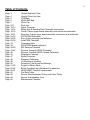
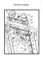
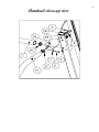
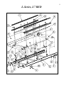
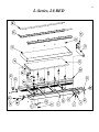
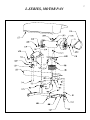
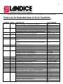
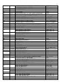
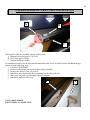
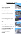
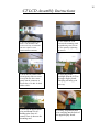
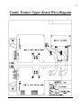
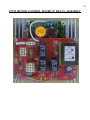
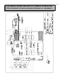
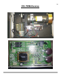
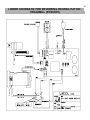
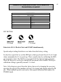
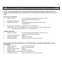
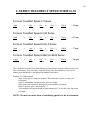
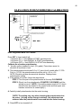
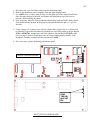
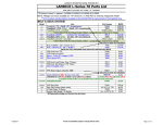
1
L760-Series
L8622/L9622-Series
Home and Commercial Treadmill
Diagnostic and Service Manual
2006
Addendum
Version C 1.0
For Technical Service Call 1-(800)-LANDICE
2
Table of Contents
Page
Page
Page
Page
Page
Page
Page
Page
Page
Page
Page
Page
Page
Page
Page
Page
Page
Page
Page
Page
Page
Page
Page
Page
Page
Page
Page
Page
Page
Page
3
4
5
6
7
8-11
12-13
14-15
16-18
19-21
22-23
24-28
29-32
33
34
35-40
41-44
45
46
47
48
49
50
51-52
53-54
55-61
62
63
64
65
Upright Exploded View
Upright Close-Up View
L760 Bed
L860/L960 Bed
Motor Pan
Parts List
Upper Consoles
Safety Key & Reading Rack Assembly Instructions
Cardio Trainer upper board assembly instructions and schematic
Executive Trainer upper board assembly instructions and schematic
ANTA/PWM Schematic
Error Codes message and definition
Anta/PWM Flowchart
Overspeed topic
ANTA/PWM speed calibration
ESI Reverse Treadmill
Reverse Treadmill (RTM) Flowchart
Reverse Treadmill (RTM ) Speed Calibration
Diagnostic Features
Speed Formulas
Elevation Calibration
L9 Elevation nut setting
Accessing Total hours and Mileage
English to Metric Mode
Button Feedback and Membrane by pass test
L8622/L9622 Treadmill replacement
Pro-Rate Table
Service Reimbursement Policy and Labor Policy
Service Authorization Form
Maintenance Checklist
3
L60 Series, Upright
4
Handrail close-up view
5
L-Series, L7 BED
6
L-Series, L8 BED
7
L-SERIES, MOTOR PAN
8
111 Canfield Avenue • Randolph, New Jersey 07869 • 1-800-LANDICE • FAX 973-927-0630
Parts List for Exploded View L7 & L8 Treadmills
Note: Always get Version number for electronic components to insure compatibility.
NUMBER MODEL DESCRIPTION
PART NUMBER
L7/L8/L9
1
DISPLAY BOARD – PRO SPORTS TRAINER
70424
DISPLAY BOARD – CARDIO TRAINER (LCD)
70481
DISPLAY BOARD – EXECUTIVE TRAINER (COLOR)
70478
L7/L8/L9 FACEPLATE – PRO SPORTS TRAINER 2
2
70484
MEMBRANE PANEL – CARDIO TRAINER (LCD)
70482
MEMBRANE PANEL – EXECUTIVE TRAINER (LCD)
70479
L7/L8/L9 READING RACK, CADDY, ASSEMBLY
3
70522-SP (-BK, TI)
L7/L8/L9
4
CONTROL PANEL END CAP, RIGHT
70246-BK (-TI)
CONTROL PANEL END CAP, LEFT
70247-BK (-TI)
L7/L8/L9 CONTROL PANEL
5
70441-BK (-TI)
L7/L8/L9 CONTROL PANEL END CAP BRACKET ASSEMBLY
6
70316
(LEFT)
CONTROL PANEL END CAP BRACKET ASSEMBLY
70315
(RIGHT)
L7/L8/L9 WIRE RETAINER, UPRIGHT
7
70349
L7/L8/L9 ENDCAP SCREW, BLACK (1/2”)
8
6-32_1/2_PFHMSB
ENDCAP SCREW, WHITE (1/2”)
6-32_1/2_PFM
ENDCAP SCREW, TITANIUM
6-32X1/2_PMSZN
L7/L8/L9 UPRIGHT COVER – LEFT (BLACK)
9
70231-BK
UPRIGHT COVER – RIGHT (BLACK)
70230-BK
UPRIGHT COVER – LEFT (WHITE)
70231-TI
UPRIGHT COVER – RIGHT (WHITE)
70230-TI
L7/L8/L9 UPRIGHT MOUNTING BOLTS
10
¼-20x3/4_TTZ
L7/L8/L9
11
STAR WASHER
¼_LW_EXT
L7/L8/L9 CROSSBAR CLAMP MOUNTING BOLT
12
1/4-20x3/4_HHMS
L7/L8/L9 HANDRAIL MOUNTING BOLT
13
5/16-18x2_HHMS
L7/L8/L9 LOCKWASHER
14
5/16_LW
L7/L8/L9 ¼ INCH DOME PLUG
15
71071
L7/L8/L9
16
CROSSBAR MOUNTING BOLT
¼-20_1.25_PMS
L7/L8/L9 STAR WASHER
17
¼_LW_EXT
L7/L8/L9 RAM CONNECTOR 1 ¼” DIA. TUBE (HANDRAIL)
18
71038
L7/L8/L9 SIDE ERGO RAIL ASSEMBLY WITH FOAM CUTBACK 71063
19
L7/L8/L9 UPRIGHT, RIGHT SIDE, (BLACK)
20
70474-BK
UPRIGHT, LEFT SIDE, (BLACK)
70475-BK
UPRIGHT, RIGHT SIDE, (TITANIUM)
70474-TI
UPRIGHT, LEFT SIDE, (TITANIUM)
70475-TI
UPRIGHT, RIGHT SIDE, (WHITE)
70474
UPRIGHT, LEFT SIDE, (WHITE)
70475
9
21
L7/L8/L9
22
23
24
25
26
27
28
29
30
31
32
33
34
35
36
L7/L8/L9
L7/L8/L9
L7/L8/L9
L7/L8
L7/L8
L7/L8
L7/L8/L9
L7/L8/L9
L7/L8/L9
L7/L8/L9
L7
L7
L7
L7
L7
37
L7
38
39
40
41
42
43
44
45
46
47
48
49
50
51
52
L7
L7
L7
L7
L7
L7/L8/L9
L7
L7/L8/L9
L7/L8/L9
L7/L8/L9
L7/L8/L9
L7
L8/L9
L7/L8/L9
L7/L8/L9
L7/L8/L9
53
54
55
56
L7/L8/L9
L7/L8/L9
L7/L8/L9
L7
57
58
59
60
L7/L8/L9
L7/L8
L9
L7/L8/L9
L7/L8/L9
61
62
L7/L8/L9
L7
ACCUTRACK C.H.R. CROSSBAR ASSEMBLY 2 (or 3)
CROSSBAR W/ FOAM, L-SERIES
MAGNETIC SAFETY LANYARD
MAGNETIC STUD
FLUX GUIDE
RAM CONNECTOR, 1/12” DIA. TUBE (CROSSBAR)
CROSSBAR/HANDRAIL MOUNTING CLAMP
END CAP BRACKET MOUNTING SCREW
WASHER – FENDER
FLAT WASHER STAINLESS STEEL
READING RACK COVER SCREW
READING RACK CONSOLE SCREW
DECK SCREWS
TRACTION STRIP (SPECIFY LEFT OR RIGHT )
VFX POST SCREW
STAR WASHER
SIDE FRAME COVER, RIGHT
SIDE FRAME COVER, LEFT
L760, TREADBELT
L760, TREADBELT ORTHO
DECK SPACER
TAKE UP ROLLER
DRIVE ROLLER
DRIVE ROLLER SHEAVE
L760 – DECK
FELT WASHER
¼ NUT
BELT GUIDE
BELT GUIDE SCREW
SAFETY BRACKET
SAFETY BRACKETNUT
VFX DECK POST , L7
VFX DECK POST, L8
VFX DECK LOAD WASHER
DECK SLAT SCREWS AND L8 FRAME SCREWS
VFX DECK IMPACT ABSORBER
VFX DECK IMPACT ABSORBER, RED
#8 ZINC LOCK WASHER
BED END CAP SCREW
TAKE UP ROLLER BOLT WASHER
END CAP, BED, RIGHT
END CAP, BED, LEFT
FOOTBOLT
SOLID FOOT
FOOT – L9
VFX DECK SLAT
L760 - SIDE FRAME, RIGHT
L760- SIDE FRAME, LEFT
VFX DECK IMPACT ABSORBER, RED
DRIVE ROLLER SCREW
70445-SP
70341
71011-NEW
70492
70340
71070
70461
8-32_1/2_MSZ
¼_LW_EXT
¼_FW_SAE
8x1/2_A_PPSTSZN
1/4-20X3/4_HHMS
¼-20_1.3/4_TTZ
70469
¼-20_9/16_MSZN
¼_LW_EXT
70464 (-BK, -TI)
70465 (-BK, -TI)
70468
70534
70219
70237
70236
CV-18-2
70466
70220
¼-20_WELD_NUT
70208
8x1_A_PPSTS_ZN
70204
¼-20_WELD_NUT
70216
70297
70217
¼-20_3/4_TTZ
70221
70221-R
8_LW
8-32_3/4_TTB
3/8_FW_BL_OX
70369 (-BK)
70370 (-BK)
¼-20_3/4_TTZ
70008
70421
70240
70462 (-BK, -TI)
70463 (-BK, -TI)
70221-R
¼-20x3/4_HWFL
10
63
64
65
66
67
68
69
L7/L8/L9
L7/L8/L9
L7/L8/L9
L7/L8/L9
L7/L8/L9
L7/L8/L9
L7/L8/L9
71
72
73
74
75
76
77
78
79
L8/L9
L8/L9
L8/L9
L8/L9
L8/L9
L8/L9
L8/L9
L8/L9
80
L8/L9
81
82
83
84
85
L7/L8/L9
L7/L8/L9
L7/L8/L9
L8/L9
L8/L9
86
L8/L9
87
88
89
90
91
92
93
94
95
96
97
98
99
100
101
102
103
104
105
106
L7/L8/L9
L7/L8/L9
L7/L8/L9
L7/L8/L9
L7/L8/L9
L7/L8/L9
L7/L8/L9
L7/L8/L9
L7/L8/L9
L7/L8/L9
L7/L8/L9
L7/L8/L9
L7/L8/L9
L7/L8/L9
L7/L8/L9
L7/L8/L9
L7/L8/L9
L7/L8/L9
L7/L8/L9
L7/L8/L9
107
L7/L8/L9
L7/L8/L9
TAKE UP ROLLER BOLT
NAMEPLATE, READING RACK
LEFT, READING RACK BUCKET
RIGHT, READING RACK BUCKET
TOP, READING RACK
KEYHOLE PLATE, READING RACK
BOTTOM, READING RACK
UPRIGHT CONTROL PANEL FRAME SCREW
SHEAVE, DRIVE ROLLER, L8
DRIVE ROLLER,L8622
TAKE-UP ROLLER,L8622
DECK,L8/9,22"
FELT WASHER, L8622
SPACER, 8622
SLEEVE, SPACER, L8622
TREADBELT, L8622
TREADBELT, L8622 ORTHO
END CAP, BED, BLACK, L8622-RIGHT
END CAP, BED, BLACK, L8622-LEFT
RUBBER MOTOR COVER GROMMENT
MOTOR COVER FINISHING WASHER
MOTOR COVER SCREW
TREADSTRIP (PEGGLY GRIP TAPE)
SIDE FRAME COVER, RIGHT
SIDE FRAME COVER, LEFT
SIDE FRAME RIGHT, L8622
SIDE FRAME LEFT, L8622
HITCH PIN FOR AXLE, WIDE
WHEEL AXLE, WIDE
WHEEL, WIDE
BEARING BLOCK BOLT
BEARING BLOCK SPACER, WIDE
ELEVATION PIN
ELEVATION PIN SCREWS
CLEVIS BOLT HARDWARE
HITCH PIN(MOTOR BRACKET AND CLEVIS)
ELEVATION LEG RUBBER BUMPER
MOUTOR MOUNT SPACER, RUBBER
MOUTOR MOUNT SPACER, METAL
TENSION SCREW NUT
TENSION SCREW FLAT WASHER
FOAM BLOCK
CLEVIS PIN
ELEVATION POTENTIOMETER
ELEVATION NUT
MOTOR BRUSH CAP
MOTOR BRUSH, 110V
MOTOR BRUSH, 220V
MOTOR BRUSH HOLDER
3023
70454
70522-BUCKETL
70522-BUCKETR
70522-TOP
70522-KEYHOLE
70522-BOTTOM
¼-20x3/4_TT
70290
70504
70505
70296
70516
70506
70515
70513
70535
70508-BK
70509-BK
1259
10_Finishing_W
8-32_3/4_TTB
70293
70286 (-BK, -TI, -RR)
70287 (-BK, -TI, -RR)
70510 (-BK, -TI)
70511 (-BK, -TI)
213
70359
70358
¼-20_2_MSZ
70403
70032
¼-20_9/16_MSZN
70345
233
2215
70090
70089
¼-20_NUT
1/4_SHOULDER_W
70103
70063
71013
MISC
MISC
70222
70223
MISC
11
108
109
110
111
112
113
114
L7/L8/L9
L7/L8/L9
L7/L8/L9
L7/L8/L9
L7/L8/L9
L7/L8/L9
L7/L8/L9
SPEED SENSOR BRACKET
SPEED SENSOR
FLYWHEEL FLAT WASHER
ELEVATION CLEVIS
BEARING BLOCK WASHER, WIDE
BEARING BLOCK, WIDE (SINGLE PIECE)
TENSION SCREW
70067
71007
¼_FENDER_W
70049
70402
70373
70071
115
118
119
L7
L8/L9
L7
L8/L9
L7
L8/L9
L8/L9
L7/L8/L9
L7/L8/L9
120
L7/L8/L9
121
122
L7/L8/L9
L7/L8/L9
123
L7/L8/L9
ELEVATION LEG ASSEMBLY, WIDE
ELEVATION LEG ASSEMBLY, WIDE
DRIVE BELT, L760
DRIVE BELT, L860
MOTOR COVER AERO, L760
MOTOR COVER, L860
MOTOR COVER AERO, L8622 & L9622
MOTOR PAN
ELEVATION MOTOR W/ POTENTIOMETER, 110V
ELEVATION MOTOR W/ POTENTIOMETER, 220V
DRIVE MOTOR, 110V
DRIVE MOTOR, 220V
FLYWHEEL
MOTOR BRACKET
MOTOR BRACKET, L8622
MOTOR BRACKET SCREWS
70367
70374
220J10
70291
70520-SP
70523-20-SP
70523-SP
70373
70088-C-SP
70126-SP
70014
70125
70010
70071
70507
1/4-20_9/16_MSZ
116
117
12
Series Pro Sports Trainer Faceplate
Models That Use This Faceplate:
L7-PST, L8-PST, L7-LTD-PST, L8-LTD-PST, L7-CLUB-PST, L8-CLUB-PST, L9-CLUB-PST.
Production Time Frame: 2003-Present
Electronics: : PWM/Relay Combo motor pan on all Home Units, 110V SCR commercial motor pan
for
LTD’s and 110V CLUB’s, 220V SCR commercial motor pan for 220V CLUB units. See Wiring
Diagrams.
Settings Used In: Home and Commercial (LTD’s and CLUB’s)
Key Features: Closed Loop Treadmill (w/ speed sensor), Safety Lanyard, 0.5-12MPH Push Button
Speed
and Elevation Control (11MPH on LTD’s and CLUB’s), 4 Built in Programs, 2 User Defined Programs.
L-Series Cardio Trainer LCD Membrane
Models That Use This Membrane:
L7-CT, L8-CT, L7-LTD-CT, L8-LTD-CT, L7-CLUB-CT, L8-CLUB-CT. L9-CLUB-CT.
Production Time Frame: 2003-Present
Electronics: PWM/Relay Combo motor pan on all Home Units, 110V SCR commercial motor pan for
LTD’s and 110V CLUB’s, 220V SCR commercial motor pan for 220V CLUB units. See Wiring
Diagrams.
Settings Used In: Home and Commercial (LTD’s and CLUB’s)
Key Features: Closed Loop Treadmill (w/ speed sensor), Safety Lanyard, 0.5-12MPH Push Button
Speed
and Elevation Control (11MPH on LTD’s and CLUB’s), 5 Built in Programs, 5 User Defined Programs,
Standard Wireless Heart-Rate Control, Two Color LCD Graphic Display, Numeric Keypad with Quick
Speed and Quick Grade Features, Touch Sensitive STOP switches on both left and right side,
Optional
ACCUTRAK Contact Heart Rate System on CLUB units.
13
L-Series Color Executive Trainer Membrane
Models That Use This Membrane:
L7-ET, L8-ET, L7-LTD-ET, L8-LTD-ET, L7-CLUB-ET, L8-CLUB-ET. L9-CLUB-ET.
Production Time Frame: 2003 – Present
Electronics: PWM/Relay Combo motor pan on all Home Units, 110V SCR commercial motor pan for
LTD’s and 110V CLUB’s, 220V SCR commercial motor pan for 220V CLUB units. See Wiring Diagrams.
Settings Used In: Home and Commercial (LTD’s and CLUB’s)
Key Features: Closed Loop Treadmill (w/ speed sensor), Safety Lanyard, 0.5-12MPH Push Button Speed
and Elevation Control (11MPH on LTD’s and CLUB’s), 5 Built in Programs, 5 User Defined Programs,
Standard Wireless Heart-Rate Control, Color LCD Graphic Display, Numeric Keypad with Quick Speed and
Quick Grade Features, Touch Sensitive STOP switches on both left and right side, Optional ACCUTRAK
Contact Heart Rate System on CLUB units.
L-Series Reversing Rehabilitation Faceplate
Models That Use this Membrane
L7-RTM-REV, L8- RTM-REV, L9- RTM-REV
Production Time Frame: 2004- Present
Electronics: ESI PWM-R, 110V, 220v See Wiring Diagram
Settings Used In: Rehabilitation, Physical Therapy, and Hospitals
Key Features: Closed Loop Treadmill (w/ speed sensor), Safety Lanyard, Push Button Speed
and Elevation Control, Isolation Leakage Package to keep current leakage under 100 micro-amps.
RTM: Moves in forward direction only, Speed range is from 0.0 to 12.0 mph in 0.1 mph increments, No reverse
button on display panel, Optional Remove Start/Stop switch holder.
RTM-REV: Moves in forward and reverse direction, Standard remote start/stop switch holder, Speed range in
forward direction is 0.0 to 12.0 mph in 0.1 increments. Speed range in reverse direction is 0.0 to 3.0 to 0.1 mph
increment (slow scroll). Tracking is accomplished by use of reverse guide rollers. Production treadmills to have
metal guide rollers then could change to plastic guide rollers. While belt is moving in reverse, treadbelt will
move slightly until the reverse guide rollers activate. This treadmill is slightly louder due to our treadbelt guide
system.. Reverse button on display panel has red reverse LED. The REVERSE button allows user to switch
treadbelt direction from forward to reverse and vice versa. The Rehabilitation treadmill will run in reverse when
Reverse button is pressed and red reverse light is illuminated.
14
L-SERIES MAGNETIC SAFETY KEY INSTALLATION
A
B
C
The magnetic safety key assembly consists of three parts.
A. Magnetic safety key (part # 71011-SP)
B. Flux Guide (part # 70340)
C. Magnet Stud (part #70492)
To install this assembly into an older machine that utilized the Tree-Loc (ball & socket) attachment design
proceed with the following steps:
1. UN PLUG TREADMILL
2. Remove control panel end caps and upper display assembly.
3. Remove the old style Tree-Loc socket.
4. Install new style magnet stud (B) by threading into the flux guide (A).
5. Make sure flux guide is positioned as shown in pictures.
6. Install new magnetic safety key.
B
CALL 1-800-LANDICE
FOR TECHNICAL ASSISTANCE
A
15
READING RACK ASSEMBLY
1. Check back of control panel for (4) 7/16” hex
head bolts. Make sure they are
offset from surface by ½".
2. Align (4) bolts with back of reading rack and
mount. After clearing the bolt heads, make
sure the reading rack drops completely into
place.
3. Prior to tightening the (4) bolts, check for
proper alignment and fit around the display
panel.
4. Using a 7/16” socket wrench, tighten the
(4) bolts. Drop buckets into the reading rack.
5. Using a phillips-head screw driver, gently
fasten the buckets into position with
(2) ½” inch wood screws (do not
over tighten).
16
CT LCD Assembly Instructions
1) First lay the membrane face
2) Next mount the LCD
down. You should have the
Velcro seal at top of membrane.
(Be sure to place a towel
underneath the membrane)
screen to the mounting studs
on membrane panel. Secure
LCD to panel by tightening
the screws.
3) Next take the ribbon cable
on and gently slide one corner
in and push the other corner
gently into the connector as
shown above. Do this for both
ribbon cables.
4) Next plug in the
backlight from the LCD to
the upper display board.
This plug will only go in
one way.
5) Nex flip the upper board
over and mount it to it’s
holding pins. Once it’s
seated, screw it down to the
mounting stud
6) Finally loop ribbon cable
over and plug into the back of
the upper display board.
17
Cardio Trainer Upper Board Wire Diagram
18
Cardio Trainer Upper Board Wire Diagram
CT with single pulse connection
19
Color ET Assembly Instructions
1) First place the membrane
2) Next gently pull the
on a flat surface with the
back facing upwards. Place
the membrane on a towel to
prevent scratches
brown clip out and gently
slip the ribbon cable into the
connector. Push brown clip
back in.
3) Then mount the LCD
screen to the mounting
studs on the Membrane
Panel by tightening the 4
screws
4) Next place the upper display
board on the right side of the
LCD screen and plug the other
side of the ribbon connector
into the upper board
5) Next plug the H/R cable
into the middle connector
shown above. This plug goes
in only one way.
6) Next plug in the power
supply cable from the
LCD to the Upper board.
7) Next move the upper
board face down to the left
of the LCD screen. Tighten
down display screws.
8) Loop the ribbon cable
over and plug it into the
upper display connector.
20
Executive Trainer Upper Board Wire Diagram
ET with pulse connection
21
Executive Trainer Upper Board Wire Diagram
ET with single pulse connection 1
22
PWM MOTOR CONTROL BOARD W/ RELAY ASSEMBLY
23
L60-SERIES HOME MOTOR PAN WIRING SCHEMATIC
(PWM MOTOR CONTROL BOARD WITH RELAY ASSEMBLY)
24
ERROR CODES SHOWN ON DISPLAY
Error Code: Loss of Speed Signal WITH belt movement
Meaning: upper display is not receiving signal from the speed sensor
Diagnostics: Refer to diagnostic flowchart: “Upper display lights up; treadbelt moves; speed
will not increase; L5 error”
Error Code: Loss of Speed Signal NO belt movement
Meaning: upper display not receiving signal from speed sensor because drive motor is not
moving
Diagnostic: Refer to diagnostic flowchart: “Upper display lights up but treadbelt doesn’t move;
L5 error “
25
Error Code: Grade potentiometer out of range (PO error)
Meaning: error detected in the elevation system
Diagnostic: Refer to diagnostic flowchart: “Elevation system not functioning or PO
error”
26
Error Code: Replace Safety Key
Meaning: Safety key is not recognize
Diagnostic: Replace safety key (see Safety Key Installation, page 14)
If problem persist replace upper display board
27
Error Code: Communication Error
Meaning: Upper display board is not communicating with the lower board
Diagnostic: Error can be a result to a upper/lower board failure or a upper wire harness
problem.
28
Error Code: Over Speed Error
Meaning: Treadmill speed is faster than the desired selected speed
Diagnostic: See page 33
29
NOTE: USE THIS FOR DIAGNOSING THE PWM/RELAY COMBO BO ARD
Upper display lights up but treadbelt doesn’t move: L5 Error
6.1
1. Enter Open Loop Speed Mode.(See pg. 33)
2. Press FAST until 12.0m ph is displayed.
6.2 Confirm proper line voltage input to PW M
board. Measure across L1 and L2 terminals
for proper line voltage.
NO
Is the green BELTSW light
on the relay board lit?
NO
YES
YES
1. Replace anta/relay
board.
1. Check RED wire on 9-pin harness
for loose connection or pushed pin.
2. Replace upper display board.
6.3
Is speed control wiring OK?
Purple wire from V+ on pwm board to P3 on relay board.
Orange wire from P1 on pwm board to P1 on relay board.
Brown wire from P2 on pwm board to P2 on relay board.
P3 on pwm board has no connection.
NO
Correct speed
control wiring.
YES
6.4 Is the motor wiring OK?
Check the wires from m otor to A+ & A-
NO
Correct motor
control wiring.
YES
6.5 Are the motor brushes OK?
UNPLUG treadm ill and unscrew brush caps. Verify
brushes are at least 3/8" long and slide freely, Verify
brushes are curved and have no burns or cracks. Check
springs, verify copper wire is not broken or burned.
NO
Replace m otor
brushes.
(2 required)
YES
6.6 Spin the motor shaft by hand.
Is the motor seized or is the shaft broken?
YES
Replace motor/flywheel
NO
Verify at least 90VDC from
Black (A+) wire and W hite
(A-) wire from PW M to Drive
Motor. No voltage, replace
PW M/RELAY com bo board.
Voltage, replace drivem otor.
30
NOTE: USE THIS DIAGNOSING FOR THE PWM/RELAY COMBO BOARD
Upper display lights up; treadbelt moves; speed will not increase; L5 error.
7.1 Check speed sensor alignment.
It should be within 1/16" of the flywheel
and parallel to the flywheel.
Is it out of position?
YES
Adjust speed sensor:
1. Use 1/2" wrench and loosen
the two lock nuts securing
sensor to it's bracket.
2. Adjust sensor gap to 1/16".
3. Tighten lock nuts.
YES
Repair or replace
speed sensor /
harness assembly.
NO
7.2 Unplug 3 wire speed sensor connector
from relay board. Check for pushed pins
or Loose wires.
Any found?
NO
7.3 Unplug 9 wire upper harness connector
from relay board. Check for pushed pins
or loose wires. Specifically look at 5
(Brown) and 9 (Green).
Any found?
YES
Repair or replace
upper harness
NO
7.4 Is speed control wiring OK?
Purple wire from V+ on pwm board to P3 on relay board.
Orange wire from P1 on pwm board to P1 on relay board. NO
Brown wire from P2 on pwm board to P2 on relay board.
P3 on pwm board has no connection.
Correct speed
control wiring.
YES
Replace the speed sensor.
NOTE: USE THIS FOR DIAGNOSING THE PWM/RELAY COMBO BOARD
Upper display fails to light when START is pressed.
Is the green AC PW R
light on the relay board
lit?
8.1
1. Plug a lamp into the wall outlet to confirm it
it is live.
2. Check line cord condition and connection.
3. Unplug treadmill and use a multimeter to
check the fuse. If it is bad, swap with a
spare MDA-15 fuse.
4. Plug in treadmill and use a multimeter to
check for 120VAC across HOT and NEUT
terminals of relay board.
NO
YES
8.2
Is the green VDC
light on the relay
board lit?
NO
YES
8.3
1. Check all connections to black 12VDC power
supply.
2. Confirm the wire with a dashed white line
(or ribbed black) is plugged into +VDC
terminal on the relay board.
3. Confirm the solid black wire is plugged into
SGND terminal on the relay board.
4. Replace 12VDC power supply.
5. Confirm voltage reading of 12-17 VDC
across dashed white line wire & solid black
wire.
1. Unplug the 9 wire connector from the relay board and inspect all wires for a loose
or pushed pin. Be sure harness is routed under the elevation motor.
2. Unplug the 12 wire connector from the upper display board and inspect all wires for
a loose fit or pushed pin. Check for 12 to 15VDC across the Black (+) wire and the
Green (-) wire.
3. Perform a continuity test on the upper wire harness.
Are harness wire connections intact?
YES
1. On PST’s and RTM only, remove
Faceplate from the display board and
press START button on display board. If
8.4
treadmill starts use a phillips head
screwdriver or x-acto knife to spread
fastener pins. If display board will not stay
mounted or any buttons are concave
replace the faceplate.
2. On CT’s & ET’s conduct Membrane
bypass test (See page 53) If treadmill
starts replace Membrane Panel. If not
replace the upper display board.
NO
Repair upper harness or replace
upper harness.
31
32
NOTE: USE THIS FOR DIAGNOSING THE PWM/RELAY COMBO BOARD
Elevation system not functioning or PO (Pot Out) error code displayed in the two
digit speed window.
9.1
Enter the DIAGNOSTIC MODE.
Does elevation system work properly?
YES
Proceed with re-calibrating
elevation potentiometer. (Pg. 48)
NO
9.2
Unplug 6 pin elevation motor connector from Relay.
Which button or direction has the problem?
UP
9.3
DOWN
Hold the DOWN button on the Display.
Is DNSW light on relay board lit?
Hold the UP button on the Display.
Is UPSW light on relay board lit?
YES
YES
NO
NO
1. Inspect the ORANGE (UP) wire and the PURPLE (DOWN) wire on both the
wire connector on the relay board and the wire connector on the upper display
board for loose connections or pushed pins.
2. If all harness connections are intact, then replace Upper Display Board.
9.4
Hold the UP button on the
treadmill. Is the yellow UP
light on the relay board lit?
NO
Hold the DOWN button on
the treadmill. Is the yellow DN
light on the relay board lit?
YES
YES
9.5
Do both the UP & DN light
YES
on the relay board light?
Replace
pwm/relay board
combo
YES
Do both the UP & DN light
on the relay board light?
NO
9.6 1. Inspect the Black wire (UP) and the Red wire (DOWN), on the 6 pin connector, for
on the relay board light?
2. If all harness connections are intact then replace the Elevation Motor.
33
Overspeed
An overspeed error indicates a treadmill overspeed condition. This occurs when the actual treadbelt
speed is faster than the desired selected speed. There is a potential for this to occur under the following
circumstances:
1)
2)
3)
4)
User weight is over 200 lbs., treadmill elevation is set between 10% and 15% grade,
and selected speed is set between .5 mph and 3.0
If user pushes against treadbelt causing it to go faster than speed set
Defective lower board or misaligned speed sensor
Maladjusted speed pot
Gravitational force will enable the user’s weight to move the treadbelt faster. The speed sensor will
pick up this increase in flywheel speed and send this information up to the display board electronics.
The microprocessor will then compare the actual speed to the displayed speed, determine a runaway
speed condition and shut the treadmill down. An overspeed will display in the window. This is a safety
feature built into all treadmills that utilize our closed loop speed circuitry (all current production
treadmills).
The only way to remedy an overspeed condition due to gravity is to have the user decrease the
treadmill elevation under 10% grade, or increase the speed.
If the user is holding onto handrails and pushing the treadbelt (using it like a manual treadmill rather
than a motorized one) it will cause an overspeed error.
Solution: Don’t push on the treadbelt.
It’s possible a blown motor control board is the problem. This occurs more frequently with PWM
drives than SCR drives. However, this problem is becoming rare due to the PWM circuitry that senses
this condition and shuts itself down before the drive motor receives any DC voltage at all. This means
you’ll get an LS or L5 error if your Anta/PWM or PWM is blown, not an overspeed error. This is a
safety feature on all Landice home treadmills with an Anta/PWM or PWM motor control board. The
SCR motor control boards also have internal protection to prevent an overspeed condition from
occurring due to a internal component failure.
Overspeed can also be caused by a maladjusted speed pot. Go into Open Loop Speed mode (see page
26) and check the speed. Adjust pots as necessary to bring up correct speed.
34
Speed Calibration: L-Series ANTA/PWM Treadmills
1. Enter into Open Loop Speed mode (O.L.S.) by pressing simultaneously
Executive Trainer
MENU & START
Cardio Trainer
DISPLAY & START
Pro Sport Trainer & RTM
FAST & START
2. Adjust the max speed first. Bring the set speed to 12mph. Let actual speed stabilize.
3. Adjust the MAX potentiometer on the pwm motor control board accordingly.
CW = increase speed / CCW = decrease speed.
The actual speed will be displayed in the center display window.
4. Decrease set speed to .5mph. Let actual speed stabilize. Adjust the MIN pot accordingly.
(.48 to
.52mph is acceptable)
5. Before turning treadmill off, check the MAX speed one more time for accuracy.
35
ESI PWM-Reverse
36
LOWER SCHEMATIC FOR REVERSING REHABILITATION
TREADMILL (RTM-REV)
37
LOWER SCHEMATIC WITH REVERSE RELAY
38
LANDICE Reversing Rehabilitation Treadmill – RTM-REV
How it work!
The “REVERSE” button is located in the same place as the “PROGRAM SELECT” button on a normal PST.
There is a little cut out for a red LED in the upper right hand corner of this button. Once the “REVERSE”
button is pressed, the red LED will light up, indicating that it’s in the REVERSE mode. You will see a -.0in the
speed window. Next you will hear three clicks. The belt switch relay is opening (1st click), closing the reverse
relay (2nd click) then the belt switch relay closes again (3rd click). You can now adjust the speed window to the
speed you want.
Remote Start/Stop Switch
The switch plugs into the left hand side of the upper display board. When installing a RTM-REV, run the wire
into a hole by the Contact Heart Rate harness. The wire is held in by a strain relief (same as the line cord). Then
plug it into the upper board. When you press the remote start/stop switch the treadmill will pause like pulling
out the safety lanyard. The only exception is that if you are set to a speed higher than 1mph and restart the
machine, the treadmill will start up at 1mph. If you pause it and the speed is set lower than 1mph, the treadmill
will restart at that speed.
Roller Guides for Treadbelt Tracking.
There are four roller guides to keep the treadbelt centered when it’s running in the reverse position. This helps
the belt from tracking to one side. There are four roller guides located at the front & rear deck slats. They are
positioned at the end of the deck slat and will spin when the belt starts to touch it. Refer to Diagram A for a
picture of the roller guide.
39
Washers
Roller Bearing
Deck Slat
Allen key set
screw
Diagram A
These roller guides are almost silent in forward position, but may be heard in the reverse position. The roller
guides should spin freely. Loosen the set screw with a 10/32 allen key until the roller guide to spins freely.
---NOTE: Always track the treadbelt in the forward position--Contact Heart Rate.
This treadmill has a Contact Heart Rate option and is the same set up as the L9 Club’s with Contact Heart Rate.
Nothing has changed for this feature.
Medical Rails.
This will be the same set up as any other treadmill with medical rails.
Voltage Readings off the PWM-R.
VOLTAGE POINTS
P3(AC IN) & P6(AC
NEUT)
P2(FAN +) & P4(FAN -)
P7 & P8
WIRE HARNESS
(BLK&GREEN)
P10(MOTOR+) &
P9(MOTOR-)
AC VOLTAGE
110.4-120 VAC
DC VOLTAGE
N/A
N/A
N/A
N/A
12VDC
15VDC
12-17VDC
N/A
1MPH = 10VDC
40
LED’s for PWM-R
LED
AC LINE IN
COLOR
GREEN
+12 UPPER BOARD
POWER
GREEN
BELT ON
GREEN
DOWN COMMAND
GREEN
UP COMMAND
GREEN
RELAY DN
ORANGE
RELAY UP
ORANGE
PWM
ORANGE
RUN AWAY
ORANGE
OUT CURRENT /
RESET
ORANGE
SPEED SENSE
ORANGE
REVERSE
GREEN
PURPOSE
INDICATING VAC IS
GOING INTO THE
BOARD
INDICATING VDC IS
GOING TO THE UPPER
BOARD
INDICATING THAT
THE BELT SWITCH
RELAY IS CLOSED
INDICATING THAT
THE UPPER BOARD
CLOSED THE DOWN
RELAY
INDICATING THAT
THE UPPER BOARD
CLOSED THE UP
RELAY
INDICATING THAT
120VAC IS GOING TO
THE ELEV. MOTOR
INDICATING THAT
120VAC IS GOING TO
THE ELEV. MOTOR
INDICATING THAT
THE UPPER BOARD IS
SENDING A SPEED
SIGNAL TO PWM
INDICATING THAT
THE BELT IS MOVING
FASTER THAN IT
SHOULD
INDICATING THAT AN
AMOUNT OF
EXCESSIVE CURRENT
IS GOING THROUGH
THE BOARD
INDICATING IF THERE
IS SPEED SENSOR
FEEDBACK
INDICATING THAT
THE REVERSE RELAY
IS CLOSED
NOTE: USE THIS FOR THE DIAGNOISING THE RTM (-REV) TREADMILL
Upper display lights up but treadbelt doesn’t move: L5 Error
1.1
1. Press START
2. Is the Green BELT ON LED lit on PWM-R
YES
1.2
1) Confirm proper line voltage input to
PWM-R. Measure across GROUND &
AC LINE IN terminals for proper line
voltage (120 volts ac +/-8%).
2) Confirm 12-17 volt dc from the top of
upper wire harness. (Measure at black &
green wire) Check harness connections.
3) Replace upper board
NO
1) Disconnect the drive motor wires from the
lower board.
2) Enter into O.L.S. mode (see page 45).
3) Set the speed to 12 mph.
Is the Orange PWM LED lit?
YES
1.3
Measure DC voltage out of the Motor + &
Motor – terminals.
NO
Replace PWM-R
Did you measure at least 90 DC volts?
YES
Replace PWM-R
NO
Is the motor wiring OK?
Unplug the treadmill from the wall outlet
Check the wires from motor to Motor+ & Motor -
1.4
UNPLUG treadmill and unscrew brush caps. Verify
brushes are at least 3/8" long and slide freely; verify
brushes are curved and have no burns or cracks. Check
springs, verify copper wire is not broken or burned.
Are the motor brushes OK?
YES
Replace motor/flywheel
NO
Replace
motor
brushes (2
required)
41
42
NOTE: USE THIS FOR DIAGNOSING THE RTM - REVERSE
Treadmill does not go in Reverse, No error code
2.1
1) Press the START button
2) Press the REVERSE button
NO
1) Re-seat the upper
board to the faceplate.
2) Replace upper board
NO
1) Check wire harness
connections
2) Replace upper board
Is the red LED on the REVERSE
button lit?
YES
2.2
Is the green REVERSE LED
lit on the PWM-R?
YES
2.3
Disconnect the black and
white wires from the relay
coming from P7 & P8 and
measure DC voltage.
Did you measure at least 15
volts dc?
NO
Replace PWM-R
board
YES
2.4
1) Turn machine off
2) Disconnect drive motor wires from the lower board
3) Enter into Open Loop Speed Mode (see page 33).
Increase the speed to 12 mph.
4) Measure from the Motor+ & Motor- wire terminal in volts
dc with your meter.
Do you measure at least 90 dc voltages?
1) Check if drive motor is seized
2) Check if the motor brushes
are least 3/8” long.
YES
NO
Replace PWM-R
board
43
NOTE: USE THIS FOR DIAGNOSING THE PWM-R; RTM (-REV)
Elevation system not functioning or PO (Pot Out) error code displayed in the two
digit speed window.
3.1
Enter the DIAGNOSTIC MODE.
Does elevation system work properly?
YES
Proceed with re-calibrating
elevation potentiometer. (Pg. 48)
NO
3.2
Unplug 6-pin elevation motor connector from PWM-R.
Which button or direction has the problem?
UP
3.3
DOWN
Hold the DOWN button on the Display.
Is DNSW light on relay board lit?
Hold the UP button on the Display.
Is UPSW light on relay board lit?
YES
YES
NO
NO
1. Inspect the PINK (UP) wire and the WHITE (DOWN) wire on both the
wire connector on the relay board and the wire connector on the upper display
board for loose connections or pushed pins.
2. If all harness connections are intact, then replace Upper Display Board.
3.4
Hold the UP button on the
treadmill. Is the yellow UP
light on the relay board lit?
NO
Hold the DOWN button on
the treadmill. Is the yellow DN
light on the relay board lit?
YES
YES
3.5
Do both the UP & DN light
YES
on the relay board light?
Replace
PWM-R
YES
Do both the UP & DN light
on the relay board light?
NO
3.6 1. Inspect the Black wire (UP) and the Red wire (DOWN), on the 6 pin connector, for
on the relay board light?
2. If all harness connections are intact then replace the Elevation Motor.
44
NOTE: USE THIS DIAGNOSING FOR RTM(-REV)
Upper display lights up; treadbelt moves; speed will not increase; L5 error.
4.1 Check speed sensor alignment.
It should be within 1/16" of the flywheel
and parallel to the flywheel.
Is it out of position?
YES
Adjust speed sensor:
1. Use 1/2" wrench and loosen
the two lock nuts securing
sensor to it's bracket.
2. Adjust sensor gap to 1/16".
3. Tighten lock nuts.
YES
Repair or replace
speed sensor /
harness assembly.
NO
4.2
Unplug 3-wire speed sensor connector
from PWM-R board. Check for pushed
pins or Loose wires.
Any found?
NO
4.3 Unplug 9 wire upper harness connector
from PWM-R board. Check for pushed
pins or loose wires. Specifically look at
dark blue and green.
Any found?
YES
NO
4.4
Enter into O.L.S. mode (see page
45). Is the orange SPEED SENSE
LED near the speed Molex
connector lit?
YES
NO
Repair or replace
upper harness
Disconnect the speed
sensor from the
PWM-R board. Is the
orange SPEED
SENSE LED lit?
YES
NO
Replace PWM-R board
Replace the speed sensor.
Landice Pot calibration for ESI 110-v PWM-R on
Rehabilitation treadmill
COMMANDED
0.1
0.5
1.0
5.0
10
11
12
45
MOTOR SPEED
OPEN LOOP
SENSOR
0.2/0.3
0.5/0.6
1.0/1.1
4.3/4.4
8.5/8.6
9.2/9.3
10.1
POT SETTING
MIN POT
8 o’clock
MAX POT
10:45
IR POT
11 o’clock
Enter into O.L.S. Mode is Fast and START simultaneously
Speeds and pot setting listed above are taken from the factory setting.
For best low-speed feel we set the MIN pot so that speed reads from 0.2 to 0.3 mph
when commanded to 0.1 in open loop. This is usually done by calibrating the MIN
pot around 8 o’clock. The MAX is set around 10:45 for the best high-speed feel.
Then, the IR pot is a set to give smooth belt movement with a loaded. The IR pot
calibration setting is generally around 11 o’clock.
Note: All settings are preset from the factory however by changing the necessary
speed pot the speed of the machine will vary. For torque and surging adjust the IR
pot. If the treadmill speed is not resolve from speed calibration then replace the
PWM-R board.
46
DIAGNOSTIC FEATURES ON L60-SERIES TREADMILLS
NOTE: The following information is for diagnostic and troubleshooting purposes and is meant to be
used by authorized Landice service technicians ONLY and should not be made available to the general
public.
EXECUTIVE TRAINER
1MENU/ START
234-
Accesses Diagnostic mode/Display Software version
Open loop Speed Mode/Total hours
DOWN/PAUSE/START
Reboots
METRIC/ENGLISH
Enter into Menu mode then press SETUP, finally,
Press RETURN
Press the gray circle bottom Toggles between Metric/English
NOTE: The home ET’s treadmill prior to version 1.04 does not change in grade percent
The home units with software version 1.04 and after
CARDIO TRAINER
1DISPLAY/START
234-
DOWN/PAUSE/START
MANUAL/START
UP/DOWN/START
Accesses Diagnostic mode/Displays software version
Open Loop Speed Mode/Total hours
Reboots.
METRIC/ENGLISH
Toggles 12% and 15% elevation selection.
PRO SPORTS TRAINER/REHABILITATION TREADMILL/ REVERSING REHABILITATION
TREADMILL
1DISPLAY/START
Accesses Diagnostic mode
2FAST/START
Open Loop Speed Mode.
3DOWN/PAUSE/START
Reboots
4DOWN/START
METRIC/ENGLISH
NOTE:(For PST’s with software version 2.0 and after)
5UP/DOWN/START
Toggles 12% and 15% elevation selection
47
L-SERIES TREADBELT SPEED FORMULAS
Formula: Treadbelt Speed L7 Series
1mph
1hr.
x
1rev. x
114in.
1hr. x
60min.
12in. x
1ft.
5,280ft
1mile
= 9.3rpm
5,280ft
1mile
= 8.7 rpm
5,280ft
1mile
= 7.7rpm
Formula: Treadbelt Speed L7-60 Series
1mph
1hr.
x
1rev. x
122in.
1hr. x
60min.
12in. x
1ft.
Formula: Treadbelt Speed L8 & L9 Series
1mph
1hr.
x
1rev. x
137in.
1hr. x
60min.
12in. x
1ft.
Formula: Treadbelt Speed L8622 & L9622 Series
1 mph
1hr.
x
1rev x
136in
1hr
x
60min
12in
1ft
x
5,280ft
1 mile
= 7.8 rpm
These formulas are useful for troubleshooting speed problems when the technician does not
have a tachometer. You can simply count how many times the treadbelt revolves in one
minute (rpm) and divide by the appropriate number listed above.
Example: L8 Club treadmill.
Step1: Place a piece of tape on treadbelt. This will make it easier to count your
revolutions.
Step2: Turn treadmill on and increase speed to 6.0mph.
Step3: Start your stopwatch and begin to count treadbelt revolutions.
Step4: Take your rpm’s and divide by 7.7.
Your treadbelt revolutions should be approximately 46.2 or 46; this is the equivalent
of 6 mph.
NOTE: The most accurate form of calculating speed is to use a tachometer.
48
ELEVATION POTENTIOMETER CALIBRATION
ELEVATION
POTENTIOMETER
P/N #71013
ELEVATION MOTOR
P/N #70088 110volt
P/N #70126 220volt
ADJUSTMENT
SHAFT
ELEVATION NUT
NOTE: ELONGATED BRACKET HOLES ARE FOR
POTENTIOMETER FINE ADJUSTMENT.
Enter Diagnostic Mode L60’s series:
Press OFF to turn treadmill off.
L60-Series ET’s – Hold MENU & START simultaneously
L60-Series CT’s – Hold DISPLAY & START simultaneously
L60-Series PST’s – Hold DISPLAY & START simultaneously
Calibrate the elevation potentiometer:
1. Visually confirm treadmill is level. (0% grade). Press down arrow for
elevation till machine is level.
2. The potentiometer should read 0.0 or 0.1 (zero) for all models after 11/7/00.
Prior to 11/7/00, the potentiometer should be set to –0.4 to –0.6.
NOTE: Elevation window shows actual elevation. Display shows
potentiometer setting.
3. If the setting is incorrect, follow the steps below.
STEP 1: Turn the post of the potentiometer all the way CLOCKWISE
STEP 2: Slowly turn the potentiometer COUNTER CLOCKWISE until the
setting is correct. (NOTE: If the setting seems stuck at 25.5 check
that pot wires are seated in the correct order and that upper wire
harness connection is seated tightly.)
4. Carefully install potentiometer into the motor housing.
*NOTE: The setting may vary when inserting the potentiometer into
the motor. As long as the change is minimal, fine adjustment can
achieved after the potentiometer is secured into the motor housing.
5. Press OFF to turn treadmill off.
49
Elevation Nut setting for L9 Treadmills
This setting has been revised to correct the treadmill from running off level.
With the elevation nut flush with plastic on the shaft, turn the nut 8 full turns for
the 110v elevation motors and 7 ½ turns with the 220v elevation motors.
This picture shows a properly adjusted elevation nut.
The foot is off
the ground by
approximately
1/8th of an inch.
This picture shows the treadmill set to “0%” grade. Notice the actual half
moon feet are NOT touching the ground. Meaning, the elevation legs are
supporting the weight of the treadmill.
FOR TECHNICAL ASSISTANCE CALL 1-800-LANDICE
50
ACCESSING TOTAL MILES/HOURS ON L-SERIES
TREADMILLS
***NOTE: The following applies to Landice’s latest models, manufactured after
October 1, 2003.
1. Executive Trainer
Total hours/miles on an Executive Trainer display can be accessed via Diagnostic Mode.
To access diagnostic mode follow the steps outlined below:
A. Make sure the treadmill is turned off.
B. Hold down the
and
the diagnostic screen comes up.
buttons simultaneously until
C. Total Hours/Miles will appear at the bottom of the diagnostic screen:
TOTAL HOURS 0:10
TOTAL MILES 0.7
2.
Cardio Trainer
Similar to the Executive Trainer, total hours/miles on a Cardio Trainer display can be
accessed via Diagnostic Mode. To access diagnostic mode follow the steps outlined
below:
A. Make sure the treadmill is turned off.
B. Hold down the
the diagnostic
and
buttons simultaneously until
screen comes up.
C. Total Hours/Miles will appear at the bottom of the diagnostic screen:
3. Pro Sports Trainer & Rehabilitation Treadmill
Please note there is NO way to access total hours/miles on the Pro Sports Trainer
and RTM
51
To change current production machines from English to
Metric
Pro Sport Trainer - Version 2.0
Approximately manufactured between 10/2003 – 11/2005
1)
2)
3)
Turn the treadmill off by pressing STOP
Press DOWN and START simultaneously
Press STOP
Pro Sport Trainer – Version 2.01
Approximately manufactured after 11/2005
1)
2)
3)
Turn the treadmill off by press STOP
While off press the DOWN, SLOW, and START button simultaneously
Press STOP
Cardio Trainer
Approximately manufactured between 10/2003-11/2005
1)
2)
3)
Turn the treadmill off by pressing STOP
Press MANUAL and START simultaneously
Press STOP
Approximately manufactured after 11/2005
1)
2)
3)
Turn the treadmill off by pressing STOP
Press MANUAL, CARDIO, and START simultaneously
Press STOP
52
Executive Trainer
1)
2)
3)
4)
Press START
Enter in the Menu mode and select SETUP
Select ENGLISH
Press RETURN
Rehabilitation Treadmill (Reverse)
1)
2)
3)
Turn the Treadmill off by pressing STOP
Press Elevation DOWN and START simultaneously
Press STOP
Rehabilitation Treadmill – Version 2.01
Approximately manufactured after 3/2006
1)
2)
3)
Turn the treadmill off by press STOP
While off press the DOWN, SLOW, and START button simultaneously
Press STOP
BUTTON FEED BACK IN DIAGNOSTIC
MODE
CODE#
1
2
3
4
5
6
7
8
9
10
11
12
13
14
15
16
17
18
19
20
21
22
23
24
25
26
27
28
29
Executive
Trainer
LEFT 1
(TOP)
LEFT 2
LEFT 3
LEFT 4
(BOTTOM)
RIGHT 1
(TOP)
RIGHT 2
RIGHT 3
RIGHT 4
(BOTTOM)
PREV
MENU
NEXT
START
PAUSE
FAST
SLOW
UP
DOWN
QUICK SPEED
QUICK GRADE
0
1
2
3
4
5
6
7
8
9
53
Cardio
Trainer
1
Pro Sport
Trainer
START
Rehabilitation RTM
(Reverse)
START
2
3
4
PAUSE
DISPLAY
FAST
5
SLOW
PAUSE
DISPLAY
Reverse (only on
RTM-REV)
FAST
6
7
8
UP
DOWN
SLOW
UP
DOWN
9
QUICK SPEED
0
QUICK GRADE
START
PAUSE
DISPLAY
MANUAL
PROGRAM
CARDIO
FAST
SLOW
UP
DOWN
Conducting a membrane bypass test can also test the functionality of a
membrane panel.
Membrane Panel Bypass Test
When a treadmill with a membrane experiences a loss in power to the upper
display, such as when a customer presses the START button and nothing
happens, a possible cause of this is a bad membrane panel. A membrane
panel bypass test can verify this. A membrane panel bypass test is conducted
by literally taking the membrane and bypassing its functions. The membrane
panel has small micro switches laminated inside that transmit the user’s
commands into treadmill functions. These functions can be simulated by
means of a membrane bypass:
54
1. Disconnect the silver foil ribbon cable from the membrane panel.
2. Remove the membrane panel completely from the upper display board.
3. Use a DRY towel or a terry cloth to wrap over the open area of the control panel frame.
Place the upper display board with wire harness still attached on top of the towel to
prevent it from touching any metal.
4. Look at the pins where the silver membrane ribbon cable connected to the display board.
You should note that printed on the green circuit board behind each pin is it’s specific
function.
5. Using a jumper (i.e. a jumper wire with two copper ends, a paper clip, or a voltmeter set
to continuity) bypass the start button by touching one end of the jumper to the pin labeled
GND or GROUND, and the other end of the jumper to the pin labeled START or ON.
(Note on page 2 where to locate these pins on various Landice display boards) If the
membrane is bad the treadmill will turn on and read “SAFE.”
6. If it is necessary, replace the damaged membrane panel.
CARDIO TRAINER BOARD
JUMP
THE GRD
& START
PIN
JUMP
THE GRD
& START
PIN
EXECUTIVE TRAINER BOARD
55
L8 & L9-22”WIDE TREADBELT & DECK
REPLACEMENT
Tools required:
*Power Screw Gun with #2 Phillips Head Bit
*This is the only way to remove and install deck frame cover screws.
7/16 deep socket, 1/2 & 9/16 standard sockets with 3/8 ratchet
2” extension for 3/8 ratchet (use for removal of upright)
Rubber Mallet, Lubriplate grease, Locking Pliers optional
Time required:
1 technician = 1 hour
Disassembly:
1. Turn treadmill ON and elevate to 15% grade.
2. UNPLUG TREADMILL!
3. Remove motor cover.
4. Remove upright assembly.
a. Remove control panel end caps.
b. Remove upright frame covers (pull outward from bottom).
c. Disconnect main upper wire harness from lower board.
*d. Loosen 8 total (4 each side) upright bolts; 7/16” socket with 2” extension.
* There is no need to completely remove these bolts from the frame.
e. Lift upright assembly UP and OFF.
Here is a picture of the treadmill frame with the upright assembly removed.
5. Remove right and left side frame covers.
56
a. Remove 4 Phillips head screws per cover using power screw gun and #2
Phillips bit.
b. Remove 2 #8 machine screws located on the bed end caps.
c. Use rubber mallet to pop the frame cover out of the frame rail channel.
Note: Make sure to strike the frame cover from the under side.
View-A
View-B
View-C
Strike from
underside.
57
6. Remove motor tensioning hook (7/16 deep socket); pivot motor back and
remove belt.
7. Slide drive-belt off drive motor flywheel.
8. Remove rear-take up roller; (9/16" hex head bolts located rear of treadmill).
9. Remove front drive-roller; (1/2" hex head bolts on right and left side).
7. Lift deck out of treadmill frame assembly.
SERVICE TIP: When removing the deck by yourself, it’s easier to lift one side
first. Place the handle of your rubber mallet between the deck and frame. This
58
will keep the deck free from the deck posts. Then you can walk to the opposite
side and lift the deck off.
Place handle
here.
8. Remove treadbelt.
Here’s a picture of the fully disassembled treadmill.
Deck reversal:
Landice decks are reversible. They should be reversed ONLY when a new
treadbelt is installed. You will need to remove the belt guides from the “old” side
and install them on the “new” side. The deck is pre-drilled on both sides to
accommodate the belt guides. If the deck has already been reversed then install a
new deck with the new treadbelt.
Inspection:
Inspect the VFX absorbers and hardware for condition. Remove the absorbers
from the mounting posts. Check for abnormal distortion, cracks or splits. Replace
absorber if any defect is noted. Check that deck posts are tight (use lock pliers to
tighten deck post). Apply a liberal amount of Lubriplate grease to the deck post.
Install absorbers.
59
Reassembly:
1. Lay new treadbelt into the frame assembly.
2. Slide deck between the new treadbelt and into the frame assembly.
3. Install front drive roller. Make sure the drive roller shaft notches are resting on
frame.
Note: Just start the drive roller bolts; DO NOT TIGHTEN AT THIS
POINT.
Note: Make sure the drive belt is properly located.
4. Slide the drive belt around the drive motor flywheel.
Note: Install motor tensioning nylon washer and nut but do not tighten at this
point.
5. Install the rear take up roller. Make sure rear roller shaft notches are resting on
frame.
Note: Just start the take up bolts; DO NOT TIGHTEN AT THIS POINT.
6. Install frame covers.
Note: Place frame covers in there respected locations; Use rubber mallet to
snap frame covers back down into side frame channels. Examine screw holes
for proper alignment.
7. Tension the treadbelt just enough to seat the front drive roller. Meaning: The
front drive roller has elongated mounting holes. The drive roller must be
seated against the aft portion of this elongated hole. You can assure the proper
seating by tightening the treadbelt tension. This will pull the drive roller aft
and position it for tightening.
Bolt must be seated to
rear of slotted hole.
60
8. Tighten front drive roller bolts (1/2” socket).
9. Tension drive belt (7/16” socket / make sure belt can twist to 45 degrees).
10. Install upright assembly.
Note: Be careful of the upper harness. Do not pinch the harness between the
frame and upright.
11. Plug upper harness back into the lower board. Secure harness to motor pan
holding clip.
12. Plug treadmill in. Turn on and decrease elevation back to 1% grade. Check for
proper belt tensions and treadbelt tracking.
13. Raise treadmill back to 15% grade, shut off and unplug.
14. Fit and secure the motor cover.
Note: You fit the motor cover before tightening the upright assembly to the
frame. This makes locating the motor cover mounting holes much easier.
15. Tighten upright to frame (7/16” socket). DO NOT OVERTIGHTEN!
16. Install upright covers. Align at top and snap into place using palm of your
hand.
17. Install control panel end caps.
TENSIONING
TREADBELT:
The same hex head bolts used for tracking, TENSION the treadbelt. To tighten the
treadbelt; turn both screws clockwise the same amount. Failure to turn them equally will
affect belt tracking. Need for tension is indicated by uneven belt speed and may be
sensed by sudden stopping of the treadbelt when your foot comes down on the belt.
Before tightening the treadbelt, assure that the treadbelt is loose and not the drive belt
(see drive belt tensioning below). DO NOT OVER TIGHTEN THE TREADBELT.
DRIVE BELT:
The drive belt tensioning screw is located on the drive motor bracket.
61
By turning the nut clockwise you will pull down the motor bracket, tightening the drive
belt. DO NOT OVER TIGHTEN! If you over tighten this belt you risk damaging the
drive motor shaft. To gauge proper tension, twist the drive belt between motor and drive
roller pulley.
The ideal tension, loosen until the drive belt slips and tighten until it stops, will allow
you to twist drive belt 45 degrees.
If you cannot twist the belt at least 45o the belt is too tight.
FOR TECHNICAL ASSISTANCE CALL
1-800-LANDICE
62
PRO-RATE SCALE FOR WEAR ITEMS
The pro-rate scale applies to all wear items on commercial
treadmills. Pro-rated items include the drive belt, motor
brushes, deck, and walking belt.
LTD sold after August 1, 2002 carry a 5-year parts warranty.
Club machines sold after January 1, 2003 are pro-rated under
the 5 year scale. Wear items will get covered under full
warranty for the first 6 months of ownership due to wear.
Parts will not get covered due to freight damage.
Wear items are pro-rated as follows:
Up to 6 months
6-12 months
Year 2
Year 3
Year 4
Year 5
No Charge
80%
60%
50%
40%
30%
63
SERVICE REIMBURSEMENT POLICY:
This is offered to all Landice dealers as well as all authorized Landice service
providers. Landice covers our treadmills with a 1-year labor reimbursement
policy. That means we will pay to fix our treadmill as long as it’s within one
year from the date the treadmill was purchased.
Our Policy:
Landice will reimburse the selling dealer according to our flat rate labor
schedule. If you are a service provider for Landice and do not sell our product,
you have the option of billing us direct or you can bill the dealer that you’re
providing service for. Generally, if our capped rate does not cover your labor
charge you would bill the selling dealer. The current rate is $30.00 per hour and
is capped at a maximum of one hour labor and one hour travel per treadmill
failure. Diagnostic and return trips are not covered. Note that treadbelt tracking,
treadbelt / drive belt tensioning, blown fuses, and set-up procedures are not
covered by this warranty.
Set-Up Includes: Assembly, adjusting treadbelt and drive belt (if needed),
walking the treadbelt and deck wax in, and performing any additional
adjustments that may have been upset during shipping.
The dealer must call for a service authorization number prior to performing any
service to verify the treadmill is under labor warranty. It is advisable to call
Landice from the treadmill location to successfully diagnose the problem. This
will insure that the correct part will be shipped out the first time. Labor claim
forms must be submitted within three months from the date service was
performed. Labor claim forms must be completely filled out and have the
Landice Service Authorization number at the top.
The Service Warranty covers installation of parts shown to be defective in
material or workmanship. The selling dealer is responsible for labor for
treadmills needing repairs. A Service Authorization (SA) number must
accompany any service reimbursement request. Service Authorization numbers
are given when the selling dealer or the service technician calls Landice prior
to beginning work on the treadmill. This allows Landice to verify that the
treadmill is within the labor warranty and also aids us in helping the technician
troubleshoot the treadmill. Landice welcomes technicians to call us from the
field and gives these calls the highest priority.
This Service Warranty does not cover customer instruction, installation, setup,
maintenance, or adjustments to treadbelt or drive belt.
64
SERVICE CLAIM FORM SA#
DEALER INFORMATION:
Service Dealer / Dealer Name:
Address
City
Phone(
Contact
State
Zip
State
Contact
Zip
)
CUSTOMER INFORMATION
Name
Address
City
Phone(
)
TREADMILL INFORMATION
Model
Serial #
Out of box problem
Yes
Date of Service
Date of Purchase
No
CUSTOMER COMPLAINT
SERVICE PERFORMED
TRAVEL / LABOR: Travel Time:
VALIDATION SIGNATURES
Service Rep. Signature
Labor Time:
TOTAL TIME: _________
Customer Signature
Date
IN ORDER TO PROCESS THIS CLAIM IN THE LEAST AMOUNT OF TIME,
FAX/SEND THE SERVICE CLAIM WITH THE DEFECTIVE WARRANTY PART WITHIN 3
MONTHS OF THE DATE THE SERVICE WAS PERFORMED.
DO NOT SUBMIT SERVICE CLAIMS WITHOUT SERVICE AUTHORIZATION NUMBERS.
Maintenance Checklist
Check treadbelt tension and tracking
Wipe underneath treadbelt
Check drive belt tension
Check motor brushes
Use cleaning stone to dress comutator
Vacuum under motor hood
Vacuum around and under treadmill
Lubricate deck with slipcoat if needed
Wipe down display with soft cotton & mild soap and
water.
65
66
INDEX PAGE
Accessing total miles for CT’s & ET’s only
50
Anta/PWM combo
flowchart
schematic
speed calibration
(see speed formulas, pg. 47)
22
29
23
34
Cardio Trainer LCD
assembly membrane instruction
schematic
16
17
Diagnostic Mode & features
46
Elevation Potentiometer calibration
48
Elevation leg assembly for L9
49
Error codes
CE
LS
OS
PO
SAFE
27
24
28
25
26
English to Metric mode, change
51
Executive membrane, color
assembly instruction
schematic
19
20
67
INDEX PAGE
Exploded View
Bed, L7
Bed, L8 & L9
Handrail
Motor pan
Upright
5
6
4
7
3
Membrane bypass test
53
Overspeed
33
Parts list
8
Pro-rate scale
62
Reading Rack Caddy assembly
15
RTM(-REVERSE)
faceplate
flowchart
lower board PWM-R schematic
38
41
36
relay schematic
rollers guides
speed calibration
37
39
45
Service Authorization
claim form
policy
64
63
68
INDEX PAGE
Safety key installation instruction
14
Software reboots instruction
46
Treadbelt speed formula
47
L8622 & L9622 walking belt replacement
55