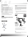
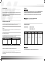
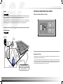
1
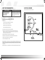
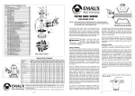
HEAT PUMP SWIMMING
POOL HEATERS
Owners Manual
OFFICES - AUSTRALIA
OFFICES - OVERSEAS
NSW - Sydney
(HEAD OFFICE)
Tel : +61 2 9898 8686
Waterco (USA) Inc
Phoenix, Arizona, USA
Tel : +1 623 434 4703
Waterco (NZ) Limited
Auckland, New Zealand
Tel : +64 9 525 7570
VIC/ TAS - Melbourne
Tel : +61 3 9879 5141
Waterco USA (Baker Hydro)
Augusta, USA
Tel : +1 706 793 7291
Waterco (GZ) Limited
Guangzhou, China
Tel : +8620 8335 1107
Waterco Canada (Focus Temp)
Quebec, Canada
Tel : +1 450 796 4333
Waterco (Far East) Sdn. Bhd.
Kuala Lumpur
Tel : +60 3 6145 6000
Waterco (Europe) Limited
Radfield, Kent, UK
Tel : +44(0) 1795 521 733
PT Waterco Indonesia
Jakarta, Indonesia
Tel : +62 21 4585 1481
WA - Perth
Tel : +61 8 9273 1900
QLD - Brisbane
Tel : +61 7 3299 9900
SA/ NT - Adelaide
Tel : +61 8 8244 6000
! WARNING
This equipment must be installed and serviced by a qualified technician.
Improper installation can create electrical hazards which could result in property
damage, serious injury or death. Improper installation will void the warranty.
Notice to Installer
This manual contains important information about the installation, operation
and safe use of this product. Once the product has been installed this manual
must be given to the owner/ operator of this equipment.
ACT Distributor
Tel : +61 2 6280 6476
Waterco Limited ABN 62 002 070 733
(WXXXXX) 03/2006
www.waterco.com
Heat Pump Swimming Pool Heaters I pg 01
Table of
A NOTE TO YOU
Thank you for buying our Waterco Heat Pump Pool Heater
A NOTE TO YOU ---------------------------------------------------------------01
GENERAL SAFETY INSTRUCTIONS ------------------------------------03
COMPONENTS DESCRIPTION ------------------------------------------- 05
INSTALLATION INSTRUCTIONS ----------------------------------------- 06
GETTING TO KNOW YOUR POOL HEATER --------------------------11
CARING FOR YOUR POOL HEATER ----------------------------------- 15
TROUBLESHOOTING ------------------------------------------------------- 17
REQUESTING ASSISTANCE OR SERVICE --------------------------- 18
GENERAL IMFORMATION AND TROUBLESHOOTING ----------- 19
HEAT PUMP SWIMMING POOL HEATER WARRANTY ----------- 20
ELECTRICAL DIAGRAMS ------------------------------------------------- 21
A heat pump pool heater is a highly efficient, cost effective method of pool heating. Intelligent operation and care
will result in many years of enjoyment and pleasure.
The Waterco heat pump pool heater is a self contained unit designed specifically for pool heating. The unit
operates on the proven principle of heat pump technology. Using the latest technology in heat collection available,
the Earth and its atmosphere, the Waterco pool heater processes the sun’s free energy extracting heat from the
sun warmed air and transferring it efficiently to the pool water. Because the Waterco pool heater moves the free
heat from the outside air to the pool water, rather than create heat, as a fossil fuel or electric resistance heater
does, the Waterco pool heater can heat your swimming pool with up to 80% lower operating costs than other less
efficient, while maintaining your water temperature at all times during the pool heating season.
In general, compared to other types of pool heaters such as gas or oil fired, the Waterco pool heater has a lower
heating capacity on a kW/ hr basis. Therefore, it will be required to operate longer to accomplish the desired
results. At certain times, it may be necessary to run the heat pump up to 24 hours per day. However, this should
not be of concern to the owner because the heater is designed to operate continuously. Even though it may
operate continuously for many hours, it will still heat the pool with far greater economy than other types of
heaters.
As with all pool heaters, you are advised to use a pool cover at night and when the pool is not in use. This will
keep evaporation, the greatest source of heat loss, to a minimum, greatly reducing the overall pool heating costs.
During warmer weather, the pool cover may not be required.
Please complete and mail in the Ownership Registration Card provided at the end of this guide. The card helps
us to notify you about any new information on your heater.
Heat Pump Swimming Pool Heaters I pg 03
GENERAL SAFETY INSTRUCTIONS
Record your model’s information
Whenever you call to request service for your heater, you need to know your model number and serial number.
You can find this information on the base of your heater.
We care for our customers
Please also record the purchase date of your appliance and your dealer’s name, address, and telephone
number.
We have provided important safety messages in this manual and on your heater. Always read and obey
all safety messages.
! WARNING
Model Number
_____________________________________
Serial Number
_____________________________________
Purchase Date
_____________________________________
Dealer Name
_____________________________________
Dealer Address
_____________________________________
Dealer Phone
_____________________________________
Our Consumer
Assistance
Centre number is.
Tel.: 1-450-796-4333
Fax.: 1-450-796-4365
Keep this book and the sales slip together in a safe place for future reference.
This is the safety alert symbol.
This symbol alerts you to hazards that can kill or hurt you and others.
!
VITAL
This is a very important label.
This symbol alerts you of things that MUST be strictly adhered to in order to ensure that your warranty
will not be voided.
IMPORTANT
These are things that must be respected in order to protect the bathers health of the swimmers and to
ensure that your warranty will not be voided.
To find detailed product information, the location of the nearest Waterco dealer
or to register your heater online, please visit our website at
www.waterco.com
Heat Pump Swimming Pool Heaters I pg 05
! WARNING
All electrical connections must be done by a qualified electrician, according to the local electrical codes. Always
cut off the unit’s main power whenever the access panel is open or removed. Always install the machine outdoors
(unless approved by the manufacturer), while respecting the minimal clearances needed for proper operation and
heating.
DO NOT DEPRIVE HEATER OF WATER FLOW FOR MORE THAN 24 HOURS WITHOUT DRAINING IT. Make
sure you leave the bypass valves open as shown in figure 1.
At the beginning of each season you must properly balance your water according to the standards prescribed on
the previous page BEFORE circulating water inside the heat pump.
At the end of each season, if the heater is no longer used, and proper pool water chemistry is not maintained, it
should be disconnected from the water line and drained to prevent any possible corrosion.
IMPORTANT
PROPER POOL CHEMISTRY IS VITAL TO THE LIFE OF YOUR HEATER. PAY PARTICULAR ATTENTION TO THE
TOTAL ALKALINITY AND TOTAL DISSOLVED SOLIDS. IT IS HIGHLY RECOMMENDED THAT YOU HAVE YOUR
POOL CHEMISTRY CHECKED OFTEN BY AN OUTSIDE INDEPENDENT POOL STORE.
Water quality standards that must be strictly adhered to:
DESCRIPTION
NORMAL RANGE*
VERIFY
PH Level
7.4 to 7.8
1 / week
Chlorine Concentration
1.0 to 4.0 PPM
1 / 2-3 days
Total Alkalinity
100 to 120 PPM
1 / 2-3 weeks
Total Dissolved Solids
below 1800 PPM Reg. Pool
1 / month
below 3500 PPM Salt. Pool
1 / month
200 to 300 PPM
1 / month
Calcium Hardness
COMPONENTS DESCRIPTION
!
VITAL
MAKE SURE THE INSTALLATION WAS DONE ACCORDING TO THE INSTRUCTIONS OF THIS MANUAL.
SEE “INSTALLATION” SECTION.
1. Heat Control
4
2. Evaporator
MAKE SURE YOUR HEATER WAS PROPERLY GROUNDED AND BONDED. SEE “BONDING” AND “BONDING
DIAGRAM” SECTIONS.
3. Cabinet
READ YOUR WARRANTY ON PAGE 23.
5. Heat Exchanger
1
2
4. Fan and Motor
3
6. Compressor
5
Inside the heater
6
Inside the heater
Heat Pump Swimming Pool Heaters I pg 07
INSTALLATION INSTRUCTIONS
Location
The location of the pool heater is very important in keeping installation costs to a minimum, while providing for
maximum efficiency of operation as well as allowing adequate service and maintenance access.
The unit is designed for outdoor installation and should not be installed in a totally enclosed area such as a shed,
garage, etc. unless ventilation is provided to ensure adequate air exchange for proper operation. Re-circulation of
cold discharged air back into the evaporator coil will greatly reduce unit heating capacity and efficiency.
The unit should be located as close as possible (3.0m is ideal) to the existing pool pump and filter to minimize
water piping. The use of 90 degree bends and short radius elbows in the water piping should be kept to a
minimum.
Mount the unit on a sturdy base, preferably a concrete slab or blocks. The base should be completely isolated
from the building foundation or wall to prevent the possibility of sound or vibration transmission into the building.
The size of the base should not be less than the base of the pool heater.
Contact your dealer to learn about our patio tile which ensures stability and reduces vibration.
IMPORTANT
Water Piping
The piping sequence: pool pump / filter / heater / pool (inline chlorinators, if used, must be downstream (after
the heater) to minimise harm to the pool equipment). See “Caring for your Pool Heater” section for more details
on chlorination and chemical feeding. Rigid PVC piping is recommended, all joints should be glued with PVC
glue. If rigid PVC is not available, you can use soft or flexible piping with stainless steel clamps. When the piping
installation is complete, operate the pool pump and check the system for leaks. Then check the filter pressure
gauge to see that excessive head pressure is not indicated.
NOTE: The installation of a bypass which isolate the heater from the water circuit is highly recommended. Make sure the
heat exchanger is not deprived of water circulation for several days, high chlorine gas could cause excessive
corrosion. If the disconnect switch is turned off, be sure the pool water is allowed to circulate through the unit, or
is drained out of it.
Plumbing Diagram
! VITAL
Waterco models discharges air either from the top of the unit. Air is pulled through the evaporator coil and
discharge through the grille. Clearance should be allowed in front and around the unit for unrestricted air
discharge and service access. See Figure 1.
IMPORTANT
When connecting the heater,
tighten the connections by hand
only. Too much pressure may
damage the water in or water
out of the heat exchanger.
1. Any kind of Automatic Chlorination System MUST be installed after (downstream) of the Heat Pump.
2. Filter MUST be connected before (upstream) the Heat Pump.
3. A bypass should be installed on all systems for water flow adjustment and ease of service.
Piping
The piping and plumbing between the heat pump and other equipment should be minimised. During colder
months, significant heat loss will occur through the piping.
Heat Pump Swimming Pool Heaters I pg 09
Electrical
Flow Check Valve
This is concerned with the installation of heat pumps below the pool water level. The heat pump operates on a
pressure switch that activates the unit when the pool pump is switched on.
If the heat pump is installed more than 1.5 metres below the pool water level, the weight of the water keeps the
pressure switch activated and the heat pump running - even when the pool pump is switched off.
In this situation, to prevent the heat pump running when the pool pump is switched off, a flow check valve must
be installed in-line with the pressure switch.
The procedure on the following pages should be carried out: (This installation was carried out on a 105 three
phase model, but the same procedure applies to all models)
IMPORTANT
To ensure your safety and ensure the adequate functioning of your heat pump, all electrical work should be
performed by a fully qualified and licensed electrician in accordance with local electrical codes.
An adequate and dedicated circuit breaker and copper wiring must be used. Refer to the electrical installation
diagram found on the inside of the access panel. It may be necessary to install a ground circuit breaker.
! WARNING
THE UNIT MUST BE DISCONNECTED BEFORE
OPENING THE ACCESS PANEL.
Installation Above Water Level
For installations where the heat pump is installed above water level, installers must ensure that sufficient water
flow is diverted to the heat pump. Flow is detected by the pressure switch. If the volume of water passing through
the heat pump is insufficient, the pressure switch will not activate and will not turn on the unit.
Bypass
A bypass must be installed with all heat pumps. This will allow the user to control the water flow through the unit,
as well disconnecting it easily for servicing.
Three Phase Connections
When installing the three phase heat pumps, the electrician must ensure at all times that the connections are done
according to the tags placed on the wires. The wiring is tagged: L1, L2, L3, and N.
SUPPLY ( AUS / NZ )
HEAT PUMP ( US / CANADA )
Electrical Connection
Standard power supply
:
208/240 v - 60hz-1 phase
Optional power supply
: 208/240 v - 50hz-1 phase
380/420 v - 50/60 hz - 3 phase
200/230 v - 50/60hz - 3 phase
MODELS
POWER
SUPPLY
BREAKER
(Amps)
Running
(Amps)
* ELECTRIC WIRE SIZE
mm2 (A WG)
-
220 / 1
20
6.5
4 (12)
-
220 / 1
20
9.5
4 (12)
-
220 / 1
20
11
4 (12)
-
220 / 1 - 380 / 3
30 - 15
14 - 60
5,3 (10) - 2,1 (14)
-
220 / 1 - 380 / 3
30 - 15
16 - 7.5
6 (10) - 2,5 (14)
L1
Blue
L1
Orange
-
220 / 1 - 380 / 3
40 - 15
18 - 80
10 (8) - 4 (12)
L2
Red
L2
Red
-
220 / 1 - 380 / 3
40 - 20
27 - 13
10 (8) - 4 (12)
L3
White
L3
Black
-
220 / 1 - 380 / 3
50 - 30
33 - 15
16 (6) - 6 (10)
N
Black
N
White
-
220 / 1 - 380 / 3
50 - 30
34 - 19
16 (6) - 10 (8)
It is essential that the electrician installing three phase heat pumps is present when the units are started up for
the first time.
Wrongly connected heat pumps are indicated by the compressor running backwards, and making excessive
noise after the 3 minute time delay. This can damage the compressor if it is left to run.
If this occurs, the unit should be turned off immediately, and the wiring should be changed by swapping any two
(2) phases to fix the problem - one phase needs to stay in the same position.
This is necessary as certain households/ properties may have three phase power supplies that are not wired to
Australian standards.
! WARNING
The power cable ground must be connected to the electrical panel and to the ground lug of the heat pump. An
improper incorrect installation may be a potential cause of fire, electrical shock or injury.
Heat Pump Swimming Pool Heaters I pg 11
GETTING TO KNOW YOUR POOL HEATER
Bonding
!
Operation of Square Electronic Control
VITAL
Because all metals have different electrical potentials, ALL metal and electrical components of the pool system
MUST be bonded together. This includes the metal framework of the pool, the light, the pump, the filter (if metal),
the heater, any automatic chlorine generator, and any other metal or electrical equipment.
On some older pools, this substructure bond wire may not exist. In these cases, a 0.9 - 1.2m solid copper rod
must be driven into the ground near the equipment, all electric equipment and metal components must be
bonded to each other and to the copper rod. Warranty will be void if system is not properly bonded.
˚C/ ˚F
ON/OFF
Bonding Diagram
!
˚C
VITAL
Pool House
Breaker Box
˚F
Chlorine
Generator
Power Supply
and Grounding
Wires Conduits
Bonding Wires
0.9 - 1.2m Coppe
r Rod
Heat Pump
l
Poo
Bon
ding
Wir
e
Light
The digital display, electronic temperature control always displays the water temperature setting. To power on the
temperature control, press the ON/OFF button.
Pool Pump
If Metal Filter
Digital Control Panel
If Pool Bonding Wire does
not exist, then a 0.9 - 1.2m Copper Rod
must be driven into the ground and
equipment bonded to it.
To modify the desired water temperature, simultaneously press on the TEMP SET control arrows on the keypad
for approximately 3 seconds, or until the temperature display flashes. The arrows will raise (up arrow) or lower
(down arrow) the temperature setting. Once the display no longer flashes, the desired temperature is now set. To
change the temperature display mode, press on the ˚C/ ˚F button.
Heat Pump Swimming Pool Heaters I pg 13
Temperature Differential
Initial Heating
It is possible for a temperature variation to occur between the probe and the pool thermostat measurement, due
the quality of the pool thermostat .i.e., the value displayed is different from the temperature displayed on the pool
thermometer. Example: if the water is at 26˚C and the heat pump displays 24˚C.
The speed of heating is dependent upon five basic factors:
To calibrate this variation, perform the following procedure;
Read the pool water temperature (ex: 26.6˚C),
Now read the temperature displayed on the heat pump thermostat (24˚C),
To determine the differential subtract the pool water temperature from the heat pump temperature,
26 (80) -24 (76) = 2˚C. Therefore we must compensate for 2˚C.
To calibrate the probe perform the following procedure;
1. Size of the pool.
2. How many degrees the water is to be heated.
3. Ambient air temperature - the warmer the air the less time is required to heat.
4. Use of a solar blanket (see the following section).
5. The size of the heater.
To achieve initial heating your pool heater and pool pump may work up to 24 hours per day until desired
temperature is achieved. The initial heating time may vary depending upon the above five factors. After initial
heating, operating time may be reduced to match daily heat loss.
Enter the digital programming mode by simultaneously pressing on the up and down arrows,
Once the temperature displayed is flashing press on the ON/OFF button,
The display will now show the calibration value, which varies -4˚C,
Using the up and down arrows, enter the calibration value, 2˚C. The degree function will flash
for negative values and will not flash for positive values.
Once the calibration has been entered wait until the new temperature appears.
To Start-Up the unit
When the unit is turned on or after a power shut down, the panel lights up and either indicates OFF or the
temperature of the pool water circulating inside the heater. Program in the desired pool water temperature.
Pool Solar Blanket
A pool solar blanket should be used whenever possible. Blankets minimise heat loss and conserve heat in your
pool. Like a jacket holds body heat in on a chilly day, or closed doors and windows hold heat in a home, the
blanket controls heat losses. Un-blanketed pools lose 2-3 times more heat than blanketed pools.
Heater Running Time
Most units should be sized to operate during the pool filtering cycle time of 8-12 hours daily, providing an even,
steady flow of warm water. On warmer days the heater will run less because the heat loss will be less. Heat pump
pool heaters are able to operate 24 hours per day when necessary.
Once programmed the fan starts and the compressor starts after a 3 to 5 minute delay.
NOTE: The fan motor and the compressor will start at the same time when the unit has been stopped for a lond period.
Defrost Cycle
To Start the unit
The unit can be stopped by switching off the electrical power supply or by programming the desired water
temperature below the actual pool water temperature.
When the ambient air temperature is between 3˚C and 7˚C, or if the evaporator is dirty or clearances are not
respected, condensation water on the fins of the evaporator tends to frost. In such a case, the control will activate
the defrost cycle until all the frost is gone. A normal defrost cycle (compressor stopped) lasts between 5 and 10
minutes. The pool heater won’t be damaged if it is running at less than 7˚C. In these conditions, the unit will have
more frequent defrosting cycles.
Heat Pump Swimming Pool Heaters I pg 15
CARING FOR YOUR POOL HEATER
Protection Devices
The integrity and performance of your pool heater and its components is protected by controls. In normal use, the
Waterco unit should never reach the thermal protection level. However, should it happen, you should verify your
operating conditions as described below.
The Waterco unit is designed to operate with a minimum water circulation of 113lpm. The high pressure switch
will shut off the compressor if there is not sufficient water flow through the unit. Check for dirty filters, clogged
skimmers or the bypass valve position. They are usually the cause of this condition.
The Waterco unit also has a built-in water pressure switch that will interrupt the operation of your unit should
water circulation through the unit stop. If there is still a demand for heat, turn on your pool pump and the heater
will start up once the normal water flow is re-established.
The Waterco pool heater has been specifically engineered to give you many years of satisfaction. To clean the
plastic surfaces use soapy water and a clean soft cloth. Never use solvents or abrasives.
The dirt collected in the evaporators can be removed with a gentle water spray and the use of a soft brush. Be
careful not to damage the aluminum fins. Do not use a pressure washer to clean the evaporator as it can damage
the fins.
Usage Of Chemical Products
IMPORTANT
Your heat pump pool heater features other protection devices that could stop the unit:
Adequate water circulation and the proper use of chemical products is absolutely necessary to protect your
family’s health and your pool heater.
High pressure cut-out switch,
Low pressure cut-out switch,
The following are essential water quality readings and must be maintained at all times.
Thermal protection for the compressor and the fan motor
DESCRIPTION
Adjustment of the bypass valves
The adjustment may vary according to the pool pump size and the climatic conditions.
HEATER
HEATER
OUT
OPEN
Cold Water
Approximately 60% of the water
is circulating in the unit.
OUT
OPEN
Warm Water
Approximately 80% of the water
is circulating in the unit.
VERIFY
7.4 to 7.8
1 / week
Chlorine Concentration
1.0 to 4.0 PPM
1 / 2-3 days
Total Alkalinity
100 to 120 PPM
1 / 2-3 weeks
Total Dissolved Solids
below 1800 PPM Reg. Pool
1 / month
below 3500 PPM Salt. Pool
1 / month
200 to 300 PPM
1 / month
Calcium Hardness
HEATER
IN
IN
IN
NORMAL RANGE*
PH Level
OUT
CLOSED
Hot Water
100% of the water
is circulating in the unit.
Winterising
!
VITAL
Set the water temperature setting to OFF. Turn the pool heater breaker OFF. If the unit is stored in a place where
the temperature drops below the freezing point of 0˚C, it is mandatory that the water accumulated in the unit
be drained completely before freezing weather prevails. The water piping MUST be disconnected to drain
the heat exchanger in preparation for winter. Once the piping is disconnected, the unit MUST be drained of all its
water by tipping it (75˚). It is recommended to flush the inside of the heat exchanger with the garden hose and to
drain the unit again. Using 2 pool return caps, block the water in and water out to prevent any intrusion. Do Not
leave the water piping connected to the heater over the winter.
DO NOT put anything under the water connect ions of the unit to lift it up. This can keep water inside the heater
and cause freezing damages.
Unit may be covered for the winter. The use of a material that will allow air to go inside the heater is
recommended.
It is also possible to fill the heat exchanger with pool anti-freeze only, but ensure that the anti-freeze contains an
elevated pH to prevent corrosion. This is optional and requires appropriate hardware.
Heat Pump Swimming Pool Heaters I pg 17
TROUBLESHOOTING
How To Protect Your Pool Heater
This Flow Chart will teach you the
steps t o follow to p rotect y our heater
as well as your family by maintaining a
corrosion free pool.
INSTALLATION
- Verify that the installation was done according
to owners’ manual instructions.
The Pool Heater Is Not Running Or Stops Less Than 2 Minutes After
Starting Up
Heat pump control set to low. Raise temperature set point.
FIRST TIME OR SPRING STARTUP
- Hook up pool water piping but do not hook
up to the Heater yet.
Desired water temperature is reached. Unit will automatically re-start when the water temperature
goes below the set point.
Main breaker is tripped. Reset it.
VERIFY & BALANCE POOL CHEMICALS
Pool pump is not running. Turn the pool pump on.
Filter is dirty restricting the water flow. Backwash and clean filter.
HEATER
IN
OUT
CLOSED
Water directed
to Pool
HEATER
IN
No
POOL CHEMICALS OK?
OUT
Yes
HOOK UP WATER PIPING TO HEATER
OPEN
SET REQUIRED WATER
TEMPERATURE ON TOUCH PAD
Water goes to
heater
IMPORTANT
When heating is not required for
less than a week you MUST leave the
Bypass valves open
(See Fig.1) to let the water circulate
in the unit. If the heat exchanger
is deprived of water circulation
for more than 24 hours, high
chlorine gas could cause excessive
corrosion.
IMPORTANT FOR THE HEALTH OF YOUR FAMILY AND
FOR YOUR POOL HEATER
- Verify Chlorine or Bromine level every 2-3 da ys.
- Verify PH level once a we ek.
- Verify Alkalinity level every 3-4 weeks (More often if you ow n
an Automatic Chlorine or Bromine Feeder.) (Above tests can
easily be done by yourself with a do it yourself kit).
- Verify Hardness and Total Dissolved Solids (TDS) once a
month (Above tests must be done by your dealer).
The Compressor Is Running But The Fan Is Not
If the unit was just installed and the compressor starts before you have programmed the desired temperature,
it is possible that the electrical hookup was made on the wrong side of the contactor (relay). Contact your
electrician.
The fan motor may be defective. Contact Waterco’s service dept.
The Fan Is Running But Not The Compressor
The unit is in its 3 or 5 minutes time delay protection mode.
No
HEATING WILL NOT BE REQUIRED
FOR MORE THAN A WEEK?
The unit is on defrost. The compressor will start again automatically a few minutes.
Yes
Shut Bypass valves and disconnect water
lines to drain the HEATER.
While your Watero pool heater is in the heating mode, a large quantity of warm and humid air passes over the
evaporator and causes condensation.
WATER QUALITY STANDARDS
TO STRICTLY ADHERE TO
7.4 to 7.8
1.0 to 4.0 PPM
100 to 120 PPM
below 1800 Reg. Pool
below 3500 Salt Pool
CALCIUM HARDNESS 200 to 300
PH
CHLORINE CONCENTRATION
TOTAL ALKALINITY
TOTAL DISSOLVED SOLIDS
There Is Water Around The Unit
HEATING NEEDED?
No
No
IS IT POOL CLOSING
TIME?
Yes
CLOSE POOL AND WINTERISE
THE HEATER
Yes
It is normal to see condensation dripping under the heater.
To verify that the water is really a water leak you will need to stop the heater and leave the pool pump
running for over 5 hours. If water is still coming out of your heater after this period you should call Waterco
for service.
Heat Pump Swimming Pool Heaters I pg19
The Heater Is Running But Desired Water Temperature
Connot Be Reached
Heat loss is too great for the heater; cover your pool as often as you can.
Evaporator is dirty.Clean it.
Evaporator restricted due to improper location.
The bypass valves are not properly adjusted.
NOTE: It your pool heater does not operate for reasons other than those mentioned above, see section
on “Requesting Assistance or Service”.
REQUESTING ASSISTANCE OR SERVICE
GENERAL IMFORMATION AND TROUBLESHOOTING
Basic Troubleshooting Guide
FAULT
POSSIBLE CAUSE
The heat pump
does not run
The heat pump is not on.
The heat pump
shuts off
less than two
minutes after
start up
The heat pump fan is not running.
If the compressor is running, then the reply may be faulty, the
fan run capacitor or the fan motor itself can be damaged.
The unit
is running
continuously
but the desired
temperature is
not achieved
The unit is located in an enclosed
area or where the airflow is
restricted, either at the intake
or the output of the energy
collectors.
Remove obstacles or relocate the unit.
The pool surface is too large for
the heat pump capacity.
ACTION
Turn on the unit, verify that the circuit breaker is on.
May need to install a larger unit, or multiple unit. Multiple units
should be installed in parallel, based on the sizing guide.
IMPORTANT
All service will be handled by an Authorized Service Centre. Warranty may be voided if service is not done by an
Authorized Service Representative. DO NOT return the heater to your dealer as they do not provide service.
HEAT PUMP TROUBLESHOOTING
Before calling for assistance or service, please check the “Troubleshooting” and “Warranty” sections or call
your dealer. It may save you the cost of a service call. If you still need help, follow the instructions below.
Using a terminal block, connect the two stripped pressure switch wires into one end, and the blue and white
wires of the flow check valve into the other end as shown (it makes no difference in which way the blue and white
wires are plugged in)
Service can be obtained by calling us at 1-450-796-4333 or by Internet at www.waterco.com.
When asking for help or service, please provide a detailed description of the problem, your heater’s model and
serial number, and the purchase date. (See the “A Note to You” section.)
This information will help us to properly respond to your request.
KEEP A COPY OF THE SALES RECEIPT SHOWING THE DATE OF PURCHASE. PROOF OF PURCHASE WILL
ASSURE YOU OF IN-WARRANTY SERVICE.
Rubber Grommet
Cut and strip this pressure switch wire leaving two exposed ends.
Feed the flow check valve wire through the underside of the control box. A rubber gromment with some silicone
sealant should be used in the entry point here to prevent any damage to the wire.
The front plastic shell can be pulled back, and the flow check wire can be fed through the underside of the control
bax.
The screws from the front of the unit need to be removed. This allows access to the underside of the power box,
where the flow check valve wire will be fed through.
Pressure Switch
Soft metal cover that needs to be pushed open with a screwdriver.
Pressure switch wire that needs to be cut, this is where the flow check valve will be wired in series.
The valve must be installed horizontally, with the stem facing up.
During installation, it is best to use some form of ducting for the lead wire of the flow check valve, and have it
running along the ground (or even underground), to prevent any trip hazards.
Heat Pump Swimming Pool Heaters I pg 21
HEAT PUMP TROUBLESHOOTING
LENGTH OF WARRANTY
WATERCO INTERNATIONAL WILL PAY FOR
Limited One to Five Years on parts
Parts and labour to correct defects in materials
and labour DEPENDING ON THE
or workmanship during the period of warranty.
HEATER PUMP MODEL
Service must be provided by an Authorized
From date of Purchase
service company.
Focus Temp International WILL NOT PAY FOR
A. Service calls to:
1. Inspect and /or correct the installation of your pool heater.
2. Instruct you on how to use your pool heater.
3. Replace house fuses or correct electrical wiring.
4. Adjust or reestablish water flow to the heater.
B. Unnecessary service calls due to erroneous problem reported.
C. Damage to your pool heater caused by accident, misuse, fire, flood, acts of God, improper
installation, harsh environment, chemical feeding before the heater or improper maintenance
of water chemistry as described in this manual.
D. Damage to internal piping or components due to freezing conditions.
E. Repairs to parts or systems resulting from unauthorized modification made to the heater.
F. Repairs not previously authorized by our service department.
G. Parts or Heater transportation to our office.
Waterco International Inc. will replace or repair, at its choice, all defective part provided that this part is sent
prepaid to our factory during the warranty period. Parts returned during the warranty period will be repaired or
replaced and returned prepaid within Canada, Australia and New Zealand by the best and most economic means
of transportation.
Waterco International Inc., is not responsible for direct or indirect damages resulting of defective components.
ELECTRICAL DIAGRAMS
Instruction on electrical connection of the manual model.