1
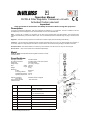
E SB-E-8-309 ISS.07 OPERATION MANUAL DVFR-8 Filter Regulator Coalescer unit with Activated Carbon element E Operation Manual DVFR-8 Filter Regulator Coalescer unit with Activated Carbon element Important Read and follow all instructions and Safety Precautions before using this equipment Description A compact compressed air Regulator, Filter and Coalescer unit suitable for 1 or 2 operators. The unit is suitable for use with the Respiratory Personal Equipment such as the Devilbiss Air Visor and Half Masks kits. Filter - Incoming air is rotated by a centrifuge unit to remove the heaviest liquid and solid particles. The remaining solid particles are collected by porous bronze filter to 5µm. The accumulated liquid can be drained using the plug in the base of the bowl. Regulator - This allows the input pressure to be reduced to a stable output pressure following initial filtering Coalescer - This removes the smallest amounts of liquids and solids down to 0.01µm. The liquid droplets are captured on micro fibres, these form large droplets and collect in the bowl which can be drained using the plug at the base of the bowl. Activated Carbon: This element filters in a similar way to the Coalescer, but will remove oil carry over to 0.003 ppm Shut of valves - Each of the 3 outlets can be isolated independantly. Model Order No. DVFR-8 Compressed air filter regulator coalescer unit with activated carbon Specifications Air supply connection Air outlet connections Gauge port Gauge range Size 1/2” BSP female. 1/4” BSP male x 3 with shut off valve 1/8” BSP female. 0 -11 bar (0-160 psi) width 305 mm height 280 mm 3.3 kg Weight Maximum: air flow air supply pressure regulated air pressure operating temperature Degree of Filtration : (micro fibre) Filter Condensate and Coalescer Drain Ref No 3500 l/min 13 bar 0-8 bar 100° C Activated Carbon 0.003ppm - Semi Automatic Part No Description 1 DV-9450806 Upper Cover Assembly including diaphragm 2 DV-9451705 Replacement Filter Element (5 µm Sintered Bronze) 3 DV-9453301-MET Metal Filter Bowl with drain valve 4 SER-3414-MF Ball Valve 1/4” BSP (M & F) 5 GA-319 Pressure Gauge 0-11 Bar 6 DV-9451711 Coalescer Filter (0.01µm) 7 DV-8000035 Isolation Valve 1/2” 8 DV-9451711AC Activated Carbon Filter © 2012 Finishing Brands UK Ltd. 2 SAFETY WARNINGS Misuse Never exceed the recommended safe working pressure/temperature for any of the equipment used. Do not use paint solvents to clean the unit or filter element. The fitting of non- recommended or non- original accessories or spare parts may create hazardous conditions. Do not install the unit above electrical or any other equipment that will be damaged by discharged condensate. Before dismantling the equipment for cleaning or maintenance, all air pressures must be isolated and released. When assembling an air pressure gauge to the unit DO NOT use a spanner, always tighten by hand. The disposal of non-metallic materials must be carried out in an approved manner. Burning may generate toxic fumes. Installation Do not install the unit above electrical or any other equipment that could be damaged by discharged condensate oil. • Ensure air flows through the unit in the direction of the arrows on the body. • Install the unit as near as possible to the point of use. An isolation valve is fitted (7) to the inlet of the unit, for convenience when maintaining and to release condensate and oil from bowls. (see operation) Slide to the right towards the regulator to open. Slide to the left to close. The unit should be mounted in an upright position. Ensure the earth lead is connected to an earth point and verify continuity from each ball valve (item 4) to another known earth point, a resistance of less than 1k ohm should be achieved for dissipation of electrostatic charge. Operation • • • a) b) Do not exceed the maximum working pressures and temperatures. When regulating the pressure always adjust from a lower pressure increasing to the desired pressure, rather than from a higher pressure down. To lock the set pressure the knob can be depressed which prevents it being adjusted. To release the lock lift the knob up. The drain valve on the bottom of the filter and coalescer can be used manually or semi-automatically. Semi-Automatic - The valve push button is rotated to the left, in this mode when the air pressure is exhausted from the unit the push button opens under spring operation. Manually - The valve push button rotated to the right shuts off the drain permanently, until it is rotated to the left when it can be pushed up to drain even when the unit is pressurised. Maintenance Always de-pressurise the whole unit prior to carrying out any maintenance work, ensuring no pressure is locked in the unit or items attached to it. The regulator knob should be wound fully to the right to exhaust all pressure after isolating. Ensure earthing of the unit is not affected by maintenance activities , see installation above. Filter - To replace this item unscrew and remove the bowl, unscrew the central bolt and pull the filter down. Coalescer - To replace this item, unscrew and remove the bowl, then unscrew the coalescer element. Care should be taken when replacing the element not to cross the threads. Gauge - When replacing this item, screw a new gauge in by hand only, do not use a spanner. Seal the thread using a liquid sealant, do not use PTFE tape. It is recommended that filter/coalescer/activated carbon elements are replaced periodically i.e. when a drop in pressure is noticeable through the unit or every 6 months. Do not use solvents or aggressive chemicals to clean the unit, which may affect the materials of construction. Always use recommended and original parts/accessories. 3 © 2012 Finishing Brands UK Ltd. Finishing Brands UK Limited, Ringwood Road, Bournemouth, BH11 9LH, UK. Tel.No. +44 (0)1202) 571111 Fax No. +44 (0)1202) 581940, Website address http:// www.finishingbrands.eu Registered office: Finishing Brands UK Limited, 400, Capability Green, Luton, Bedfordshire, LU1 3AE, UK. Registered in England: No. 07656273 Vat No. GB 113 5531 50 © 2012 Finishing Brands UK Ltd. 4 June 12