1
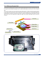
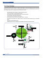
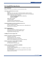
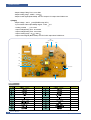
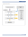
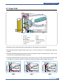
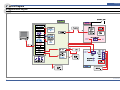
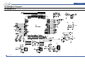
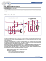
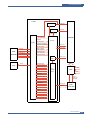
12
Circuit Description
12. Circuit Description
12.1 Engine Controller
The engine controller module consists of a motor controller, a PWM controller, a LSU I/F controller, and an ADC I/F
controller.
12.1.1 Heater Control
ENGINE CONTROL PART
AC CONTROL PART
PC1
H
N
AC
VOLTAGE
4
FUSER
1
CHOKE
2
R22 180
FUSIBLE
Vcc
R3
IC1
LM393D
D3
914T1
2
TR2 KSC
1008-Y
C
B
R7
1K
1
6
R6
5.6K
TRIAC
E
R24
120
3
Vcc
Vcc
R21
1.5K
1
D1
914T1
2
R1
R5
5.6K
BD2
R2
C1
10nF
TR1
KSC
1008-Y
C
CN1
1
BD1
B
E
HEAT
LAMP
C21
104
R4
THERM Rs
D2
914T1
C22
103
C2
1nF
2
THERMISTOR
+24Vs
R23
100
The heat lamp radiates heat by using AC power. The AC power is a TRIAC (a semiconductor switch device) which
controls a switch. The ‘ON/OFF’ control is completed by turning on/off a gate of the TRIAC through a photo TRIAC
which is insulation part.
If explaining more detail about the AC control part, it consists of passive circuit ; therefore, it turns on/off the heater
by receiving the signal from the engine control part. If the heater on signal is turned on at the engine, electricity flows
in as the LED of the PC1 (Photo TRIAC) is connected. Then, it emits light.
By this light, the TRIAC unit, a light receiving unit, becomes on, and electricity is supplied to the gate of the TRIAC.
Then, the TRIAC is turned on. As a result, AC current flows in a heat lamp, and the heat lamp radiates heat.
On the other contrary, if the signal is turned off, the PC1 becomes off, and the TRIAC is turned off due to no electricity at the gate of the TRIAC. Consequently, the heat lamp is turned off.
Special Feature of TRIAC (THY 1): 16A, 600V SWITCHING
Phototriac Coupler (PC3)
Turn On If Current: 15mA~50mA (Design: 16mA)
High Repeive Peak Off State Voltage: Min 600V
Service Manual
x
12-1