1
The Utah VHF Society
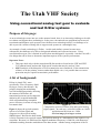
Using conventional analog test gear to evaluate
and test D-Star systems
Purpose of this page:
As new technologies come into use on the amateur bands, there is an increasing challenge to be able
to evaluate and support these technologies. In the past, conventional test equipment has been used
to maintain and diagnose such systems, but with these new technologies there is a challenge to be
able to provide a means of being able to support such systems in a meaningful way.
An example of such a technology is D-Star. As this (and similar) systems become more
widespread, the challenge to be able to design and maintain such systems increases. Using
conventional test gear, one is limited in exactly how much diagnosis is possible - but there are still a
few things that can be done to determine important aspects of the system's performance.
Important Notes:
•
•
This page deals only with the narrowband D-Star modes as found on the VHF and UHF
U.S. amateur bands, and not the "high speed" modes that may be used on 23cm.
ONLY analysis of the disruption of voice transmission was considered. If the transmission
of data is to be the primary concern rather than digital voice, it is possible that even more
protection may be required to maximize performance.
A bit of background:
D-Star is simply FM - more
specifically, it uses Frequency-Shift
keying to convey data streams. By
properly shaping the modulating
waveform and appropriately choosing
the amount of deviation, the
transmitted spectrum can be shaped to
minimize the occupied bandwidth
while still maintaining reasonable
power efficiency in terms of being able
to transmit data.
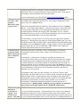
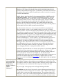
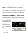
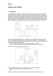
Figure 1:
Comparative spectra of D-Star (left) and typical analog
(right) signals. In each case, vertical divisions are 10 dB
and horizontal divisions are 2 kHz.
Click on image for a larger version
Figure 1 shows the typical transmit
spectra of a D-Star signal and
compares it with a typical analog
NBFM signal. Because the data stream
is fairly consistent in its spectral content, the spectral makeup of a transmitted D-Star signal is very
consistent. Because it is 4800 baud, the highest modulated frequency is 2400 Hz, with numerous
sidebands resulting from the modulation of the data stream. Another strong component of the D-
Star voice signal, as can bee seen in Figure 2, is that of the 50 Hz voice frame rate: It is this that
causes the characteristic "buzzing" sound that is heard when a D-Star signal is monitored on an
analog receiver.
As can be seen from Figure 1 the majority of the energy of the transmitted D-Star is constrained to
within a few kHz of the carrier, with "nulls" at +-3.6 kHz from the center frequency and sidebands
of decreasing energy beyond that. It is through careful shaping of the modulated signal and the
appropriate amount of deviation that this transmitted spectral shape is obtained.
D-Star baseband modulation:
The baseband modulation (that is, the signal being fed into the modulator) of the D-Star signal
consists of 0's and 1's being modulated onto the carrier, but to simply throw a 0 or 1 (represented by
a logic level) at the modulation would result in an abrupt frequency/phase change, causing the
transmitted signal to occupy considerable bandwidth. It makes sense, then, to slow down the rate of
change that can occur during modulation - but one can only go so far: With the 4800 bit-per-second
D-Star signal, we could send alternate 0's and 1's. Without filtering, this would become a 2400 Hz
square wave, but with filtering, this would turn into a 2400 Hz sine wave - a signal that would take
a fairly minimal amount of bandwidth to modulate.
Filtering the original "square wave" data into something resembling a sine wave is rather tricky. If
all that you wanted to do was to generate a 2400 Hz sine wave to transmit alternating 0's and 1's
then it would be easy, but with data, you will have a combination of 0's and 1's - sometimes several
of each in a row. When trying to filter the original data, one must make sure to minimize the filter's
"memory": Suppose that you had been sending a bunch of 0's - but then a single "1" comes along,
followed by a bunch of 0's. With a simple filter, everything will settle out to a "0" state - but when
a "1" comes along, it has to be able to fully change to a 1 - and then fully change back to a 0.
Improper filtering will tend to cause the previous state to "linger" and it can be more difficult to
determine, upon decoding, if and when, exactly, that "1" began and ended.
To solve this problem, our single "1" is turned into a smooth pulse - one that can go from 0, to 1,
and back again smoothly - and it so-happens that the filtering used to do this is Gaussian - referring
to a particular shape of the pulse and its properties. It also so-happens that with this sort of pulse
filtering, if you were to alternate 0's and 1's, you would, in fact, end up with a nice sine wave as can
be seen in Figure 3. Because the fastest that one could "change" the waveform with the 4800 baud
D-Star signal is, in fact, 2400 Hz, that is the maximum peak frequency that can be modulated.
Because we aren't sending just a "01010101" all
of the time, this nice, continuous sine wave is
constantly being interrupted to form the data
stream and in so-doing, multiple spectral
sidebands result - which is why, in Figure 2,
there is not just a peak at 2400 Hz. Instead,
energy is spread around 2400 Hz but very little
of it goes above 4800 Hz.
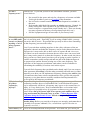
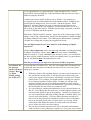
There is another important aspect of the D-Star
modulation: The amount of deviation. For
Figure 2:
mathematical reasons, good spectral and power
Spectrum
analysis
of
a baseband D-Star signal.
efficiency for this type of modulation occurs,
with data, when one sets the total deviation to be There is a null at 4800 Hz correlating with the bit
one-half of the baud rate: Because the baud rate, rate and there are strong spectral components at
intervals of 50 Hz that correlate with the 20ms
the total deviation is 2400 Hz, or +- 1200 Hz,
voice frame.
and this particular setting is referred to as
Click on image for a larger version
Minimum Shift Keying. Because we have
already pre-filtered our data with a "Gaussian"
filter, the combination is called Gaussian Minimum Shift Keying, or GMSK.
Don't let all of this scare you: All one really needs to remember is that the D-Star's baseband
modulation consists of bits of 2400 Hz sine waves.
Another important aspect of the D-Star's baseband modulation is the limitation of low-frequency
components. If too-many 0's or 1's were transmitted sequentially, the low-frequency content of the
baseband would increase and the DC level representing a 0 or a 1 could become indistinct particularly if capacitive coupling were used. Another problem with low frequency content is that
the radio's synthesizer works by locking the "average" frequency. Because this is frequency
modulation, the synthesizer was designed to avoid canceling out the modulation - but this is
typically done by preventing the synthesizer from responding to any by the slowest changes in
frequency. If the baseband modulation has too much low-frequency content, the synthesizer will
attempt to track it and cancel it tout. As it turns out, the data stream used for D-Star voice has some
fairly low-frequency components, most notably the 50 Hz "voice frame" rate. Because of this, the
frequency response of the baseband must extend down well below 50 Hz to avoid distortion of the
waveform.
D-Star transmitter and receiver:
As it turns out, the D-Star transmitter is just an FM transmitter - with a few special considerations
given to assuring that it will properly pass both low (<30 Hz) and high frequency (to 4800 Hz)
energy with a minimum of distortion. Likewise, for reception, a D-Star receiver simply takes the
demodulated signal from the discriminator and passes it to the modem board.
Because D-Star is just FM, it follows that standard test gear designed for use with FM
communications gear may be useful in the evaluation and diagnosis of D-Star equipment - although
the techniques for doing so are different for standard analog voice.
Tests using analog test gear:
There are a number of tests that one may do using normal test gear to verify performance of a DStar radio. To some extent, these rely on the assumption that the codec in the radio is working
properly, but if there are other problems with the system, one may be able to determine what they
are.
Transmit power test:
Being that the D-Star transmitter is simply an FM receiver with a digital codec, one can perform
normal tests for forward and reflected power: No surprise there.
Frequency test:
It is possible to use ordinary means to determine whether or not a D-Star transmitter is onfrequency: The modulation should not skew readings to any significant degree. If one is using a
radio capable of different modes (e.g. FM as well as digital voice) then one may simply switch the
radio to an analog mode to check to see if the radio is within specifications.
SINAD test:
One common test of receive system performance is the SINAD test. For this test, a single, precise
tone is generated - usually 1 kHz - at a standard deviation - usually +-3 kHz in the U.S. The level
of this tone is then compared to the amount of noise that is NOT at 1 kHz. For a full-quieting
signal, a SINAD reading of over 30 dB may be expected for most radios, while a SINAD of just 12
dB sounds quite noisy, but is still easily intelligible to most people.
Switching a D-Star capable radio to analog and running a SINAD test is a convenient way to verify
its performance. Note, however, that for the D-Star digital modes, FM-Narrow mode is used.
Because the nominal peak deviation in "narrow" mode is +-2.5 kHz, a deviation of +-1.5 kHz is
often used instead of +-3 kHz for the 1 kHz test tone.
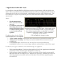
"Equivalent SINAD" test:
It is possible to relate the SINAD in FM-Narrow mode to the performance in D-Star digital voice
mode. This is is possible because the SINAD measurement tells us something about the amount of
extraneous noise in the receiver's baseband - something that correlates well with data errors. This
test is handy as it requires no special test gear at all, other than what would be used for SINAD
measurement.
Notes:
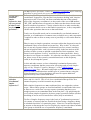
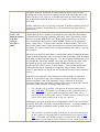
•
For the measurements
below, an Icom IC-91AD
was used.
• It is unknown at the time of
this writing what sort of
Figure 3:
analog baseband test signal Baseband waveform of a D-Star signal. In this image can be
is readily available from the
seen a period of alternating 0's and 1's (toward the right.)
receiver module of Icom
Also evident from this picture is a bit of DC level (or low
repeaters.
frequency) shift caused by the IC-91AD's synthesizer
attempting to track the data.
For this test, three levels of D-Star
Click on image for a larger version
signal disruption were investigated:
1. "Clean" audio decoding: No bit errors were observed over a period of 60 seconds or so.
2. "Mostly clean" decoding: One "bloop" (an unrecoverable bit error) occurred every 10
seconds or so.
3. Loss of D-Star sync: At this error rate, not only has recovered speech become
unintelligible, but the receiver can no longer maintain synchronization on the D-Star signal.
For this test, two types of situations were simulated using test equipment:
•
•
Weak signal degradation: For this test, the signal level of a D-Star signal was reduced until
each of the 3 levels of D-Star signal disruption were achieved.
D-Star adjacent channel degradation: For this test, another D-Star signal was generated 8
kHz offset from the one being received. With the test signal set at -90 dBm, the level of the
interfering signal was increased until each of the three levels of D-Star signal disruption
were achieved.
When each of the three levels of disruption were reached, the IC-91AD was switched to FMNarrow mode while, at the same time, the test generator was switched from generating a D-Star
signal to generating an FM signal modulated with a 1 kHz tone at +-1.5 kHz deviation: At this
point, an un-weighted SINAD measurement was taken using the audio from the IC-91AD's speaker
connector.
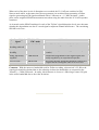
As it turned out the SINAD readings for each of the "D-Star" signal disruption levels were the same
whether the degradation was due to a weak signal or adjacent-channel interference. The correlating
SINAD levels were:
Quality of digital
signal
SINAD in "Narrow
FM" mode
Additional comments
"Clean" D-Star
decoding achieved
17-18dB SINAD
No audible decoding errors of digital audio
"Mostly clean"
decoding
15.5-16dB SINAD
Occasional "bloops" in audio (approx. one every 10
seconds)
"Ratty, but mostly
copyable"
12dB SINAD
Considerable degradation in the digital signal, but
mostly copyable by an experienced operator
"Loss of sync"
9dB SINAD
The D-Star decoder would not maintain reliable lock
of signal and no intelligible audio was recovered
Comment: With the narrower bandwidth used for D-Star recording, a theoretical 2-2.5 dB weaksignal gain should be obtained due to the reduction in detection bandwidth, as compared to the
"normal" (+-5 kHz) FM mode. In reality, this difference is closer to 1 dB owing to some S/N gain
in the wider bandwidth due to the wider deviation.
Comparison of Analog and Digital signals of equal levels:
For this test, the following configuration was used:
•
•
•
•
•
•
An Icom IC-91AD was used to generate a signal in FM-Wide (+-5kHz) mode.
Both analog and digital signals were received using an Icom IC-2200H.
The signal/noise of the received was reduced and SINAD measurements were taken using a
1 kHz tone modulated to +-3kHz.
SINAD readings were measured using the external speaker connector of the IC-2200H using
both "unweighted" (unfiltered) and CCITT weighting as noted.
At each "step" of SINAD readings, the 1 kHz tone used for the SINAD measurements was
sent, analog voice was sent, and then both the IC-91AD and IC-2200H were switched to DStar voice (DV) mode.
For each test, the audio from the IC-2200H was recorded.
These recordings consist of three parts:
•
•
•
About 10 seconds of 1 kHz tone as received in analog mode used for measuring the SINAD.
A voice recording transmitted and received in analog with the peak deviation set to +-5 kHz,
the standard for analog FM use with the IC-2200H set for "Wide" FM mode (e.g. standard
for +-5kHz deviation.)
One or more repetitions of a voice recording as transmitted and received in D-Star mode.
Quality of
analog signal
12dB
unweighted
SINAD (13dB
CCITT)
Link to
recording
Comments about analog signal
quality
Comments about digital signal
quality
Analog signal is copyable by the
majority of listeners with little or
no difficulty.
Noticable degradation of the
digital stream, but still generally
copyable speech.
7dB unweighted 7dB
SINAD (10dB SINAD
CCITT)
Test
Analog signal is quite noisy,
copyable by experienced operators
with little or no difficulty and with
only minor difficuly by
inexperienced listeners.
There was considerable
degradation of the digital stream
resulting in "recognizable but
mostly uncopiable" speech.
3dB unweighted 3dB
SINAD (5dB
SINAD
CCITT)
Test
Analog signal is very noisy,
general copyable by experienced
listeners and with some difficulty
by inexperienced listeners.
The receiver would not lock on
digital signal: Signal was
briefly boosted 10dB to force
lock and then reduced to the
original level.
12dB
SINAD
Test
Comments:
•
•
•
•
•
•
The above recordings have been MP3 compressed to reduce file size and the fidelity of the
analog portions, especially in the presence of noise, may suffer somewhat. (Uncompressed
versions of the above files may be obtained by changing the .mp3 suffix in the above links to
.wav).
At the 12dB SINAD level, it usually took 2-5 seconds for the digital voice stream to acquire
lock.
When a D-Star transmission begins, it is preceded by a short preamble that is used by the DStar decoder to rapidly recognize and acquire lock onto the signal. If this preamble is
missed, as may be the case when signals are weak and/or multipathy, it can take several
additional seconds for D-Star decoder to lock onto the signal and produce audio.
At the 7dB SINAD level, the D-Star decoder usually locked within 5-7 seconds, but only a
few bits of the speech were recognizable.
As mentioned above, the D-Star decoder would not reliably lock onto the D-Star signal at
the 3dB SINAD level: The D-Star signal was briefly boosted (during "This is K7") by 10dB
to allow the receiver to lock onto the signal and then reduced again to the 3dB SINAD level.
At weaker signal levels (7-12dB SINAD) slightly better results (1dB or so) were obtained
with the digital signal when the deviation was artificially boosted to the 3-4 kHz range, well
above the recommended 1.2kHz setting. Note: This is not a recommended practice as it
causes the transmitted signal to significantly exceed the design bandwidth of D-Star.
"Why are your results different from those obtained by the
ARRL?"
In the June, 2005 issue of QST, there was a review of the Icom IC-V82 HT. Associated with this
review was a brief overview comparing D-Star and Analog FM signal performance. ARRL
members may read this article here: http://www.arrl.org/members-only/prodrev/pdf/pr0506.pdf
In this article the ARRL lab reports that a D-Star signal maintained "...solid, virtually noise-free
communication, equivalent to 'full-quieting' at any analog SINAD above 6dB." Our results do not
reflect this and we thought that the discrepancy was likely a result of possibly different
methodologies used in measuring SINAD. Fortunately, the ARRL has put their "Test Procedures
Manual" (available online to ARRL members at this URL: http://www.arrl.org/membersonly/prodrev/testproc.pdf ).
Having reviewed the ARRL's procedures for measuring SINAD and determined that our methods
are equivalent to theirs, we are at a loss to explain the discrepancy between our readings and those
stated in the June 2005 article, or why the results obtained by the ARRL lab do not correlate with
the Icom's own specifications: If you conduct similar measurements, please inform us of your
results!
Checking the deviation of a D-Star transmitter:
To create an MSK signal, the deviation of D-Star transmitter should be set to +-1.2 kHz: As
mentioned above, this value is chosen so that the total amount of deviation (2.4 kHz) is equal to half
of the bit rate of 4.8 kbps to generate an optimum signal.
To verify that a D-Star transmitter is set up properly, one may use the same methods used for
setting the deviation of any FM transmitter. An important note here: For this test, one must make
sure that the test equipment is measuring "flat" FM rather than PM, or FM with some sort of
filtering switched in (e.g. CCITT, etc.)
There is a caveat with this measurement, however: Some of the Icom radios (such as the IC-91AD
and IC-2200H) tend to suffer from "PLL Wander" as can be seen in Figure 3. This is caused by the
radio's synthesizer trying to track low-frequency components (such as the 50 Hz "voice frame rate")
of the D-Star waveform with the result of the transmitter wandering up and down several hundred
Hz about the center frequency. The result of this is that the "deviation meter" on many pieces of
test equipment may read an amount of deviation higher than that of the D-Star's modulation. If this
occurs - and the deviation is set to +-1.2 kHz, this could result in the actual D-Star deviation being
set a bit too low, causing a slight amount of degradation of the signal.
The amount of "excess" deviation seems to vary from radio to radio and it probably varies with
operating frequency band (e.g. VHF or UHF) and the temperature and age of the radio as well. In
our tests, the amount of deviation for the same radio also varied, depending on which devation
meter we looked at and how it was able to track the low-frequency components: Some deviation
meters were fast enough in responding that this "frequency wobble" caused the meter to read only
slightly high - that is, about +-1.4 to 1.5 kHz for a signal modulated to +-1.2 kHz, while others
seemed to accurately read the total amount of frequency swing, which caused readings as high as +1.7 kHz.
There is a solution to this: The use of the monitor scope. Many service monitors or
communications test sets include an oscilloscope (either analog or digital) that may be read to
determine the precise deviation of a signal being received. On these scopes, one can see the
"frequency wobble" - but, if the scope is correctly adjusted, you can also make out the modulation
waveform itself, apart from the "wobble" and determine the true amount of deviation.
Generating D-Star signals with analog test gear:
Because a D-Star signal is simply a special case of an FM signal, generated by applying an
appropriate baseband signal to an FM transmitter, it would make sense that one could apply this
same type of baseband signal to a good-quality frequency modulator and create a D-Star signal.
Some intrepid hombrewers have done this by adapting an Icom D-Star module for their own use
and interfacing it with their own transmitter: This method works well, but it can be rather
complicated and expensive.
There is another way: Using a "canned" D-Star transmission.
Because the baseband is simply audio, it would make sense that one could simply "record" this
audio from a D-Star transmitter and play it back later - and this is, in fact, true! There are several
caveats:
•
•
•
•
•
The source baseband audio must be "flat." What this means is that "discriminator audio" is
required as this has no audio bandpass filtering or de-emphasis. Many service monitors or
test sets have "demod" outputs, directly from the discriminator that have excellent frequency
response - from near DC to well over 10 kHz. Note that many test sets also have various
audio filters (such as CCITT or some type of equalization) that should be disabled.
The source baseband audio must be "clean." For a faithful recording to be made, it should
be as free of noise and distortion as possible. If one is using a service monitor, this is easily
accomplished by connecting the transmitter directly to the service monitor (as one would do
to measure transmitter power) and make a recording. The fact that the bandwidth of the
receiver in the service monitor is wider than that of a D-Star receiver is of little consequence
if the signal is strong enough.
The recording system must be capable of frequency response from a few 10's of Hz to at
least 10 kHz. Fortunately, most computer sound cards fit the bill very nicely!
The playback system must be capable of frequency response from a few 10's of Hz to at
least 10 kHz. Again, most computer sound cards work well for this.
The modulator must be a "flat" FM with no pre-emphasis, filtering or equalization of any
kind. It must be capable of flat frequency response from a few 10's of Hz to about 10 kHz.
For our initial test, we simply connected the DEMOD output of a service monitor (a Schlumberger
4031 for the majority of our tests) tuned to the transmit frequency of the D-Star transmitter (an IC91AD) to the Line Input of a laptop computer. Using a program such as Audacity, we then
recorded the audio from the D-Star transmission to a .WAV file. We made sure to start the
recording just before the transmitter was keyed up and to stop the recording after the transmitter
was unkeyed to be sure to capture the "key" and "unkey" portions of the D-Star transmission.
For playback, we simply connected to the Line Output of the sound card to the external
modulation input of the service monitor. We then played back the D-Star waveform, adjusting the
deviation to +-1.2 kHz as described above.
Sample rates of baseband audio files:
For our initial recording, we set the sound card to a sample rate of 44.1 kHz with 16 bit audio to
generate an uncompressed .WAV file. In later tests, we found that a sample rate of 22.05 kHz at 16
bits was also adequate with only a very slight (and probably insignificant) degradation in the
baseband waveform.
We also experimented with resampling of the 44.1kHz/16 bit waveform down to an 8 kHz/8bit
waveform and found that, although the baseband waveform became slightly "ringy" owing to a very
slight amount of aliasing, there was little degradation in the ability of the D-Star receiver to decode
the signal under poor conditions. Note that recording and then down-sampling to 8 kHz/8bit is
likely to yield better results than recording at 8kHz/8 bits owing to the fact that the software
resampling is likely to be of higher quality than "capturing" a signal live and relying on the sound
card's hardware and drivers to do the appropriate filtering "on the fly."
Later, we took the 44.1 kHz 16 bit audio file and used WinLame - a freeware program - to encode
the original .WAV file to MP3. Through experimentation, we observed that recoding this .WAV
file to 128kbit/second mono (with 44.1kHz sampling) produced a fairly good replica of the original
D-Star baseband waveform and rates of lower than 64kbps (in mono) produced usable (although
somewhat degraded) results. If stereo coding is used, a bitrate of 192 kbps or higher is
recommended.
Note: Most MP3 encoding utilities do not offer the users specific options for encoding, such as the
selection of sample rate and whether the result should be a stereo or mono .MP3 file. If this is the
case, simply select the "highest" quality mode available until the quality of the playback waveform
can be closely analyzed.
We then loaded the .MP3 files into a number of different portable audio players - some of them
fairly expensive, and one of them extremely cheap (e.g. <$20) and we found that they all worked
fine.
Playing back "canned" D-Star baseband recordings:
When doing a playback of a "canned" D-Star recording, there are a number of things to remember:
•
•
•
The "keyup" and "unkey" portions of the transmissions should be preserved to allow the DStar receiver's codec to gracefully detected the begin and end of the transmissions. This
means that the recording should be started before the transmitter being recorded is keyed up
and stopped after the transmitter is unkeyed.
When playing back, be absolutely certain to disable all audio effects! Many sound cards
have treble, bass, equalization, reverb, echo, and/or "3D" effects - all of which should be
disabled before playback as any one of these can wreck the D-Star waveform!
Many portable audio players also have settings for equalization and some may even have
some other fancy audio effects - all of which should be disabled. (This was important
enough to say twice!)
•
•
You may need to do an audio phase inversion in playback to be able to decode the D-Star
waveform. If you experiment with multiple audio playback devices (e.g. different
computers, portable audio players, etc.) or different service monitors, you should remember
that each of these may or may not require a phase inversion. Because most audio players do
not have a way to flip the audio phase, you must take this into account! Remember: If you
use a compressed audio format, you should flip the phase before compressing it from the
original .WAV file, remembering that the MP3 conversion itself *may* cause its own phase
inversion. Most audio editing software packages (like Audacity) can be used to "flip" the
phase using the "invert" function, or build a simple op-amp circuit that will allow you to
reverse the phase with the flip of a switch.
Any data input or callsigns programmed into the transmitter at the time of the recording will
be maintained through the recording. If you plan to use the "canned" D-Star recording as a
test signal, make sure that your callsign and other configurations are set appropriately! If
this original recording is made using a digital data mode, it may be possible to generate a
rudimentary BER test system.
What might be put on the "canned" recordings?
Some obvious examples are:
Plain speech announcing the test. This is a good test to see how things sound and to determine if
decoding errors are occurring.
•
•
Standard tones. Using the procedures in the Icom service manual, one can feed a standard
tone into the microphone connector at a known level. This is particularly useful in a system
where D-Star audio may be converted to analog, as might be the case on an D-Star<>Analog
gateway. (Note: Under certain conditions, the D-Star audio codec may produce
unexpected results with a constant tone!)
If the transmitter was in data mode, known data may be transmitted for the purpose of
analysis to determine the magnitude of data corruption or loss.
What can you do with the "canned" recordings?
Using a standard piece of analog test gear and a portable audio recorder, it is possible to generate a
standard D-Star test signal to test the performance of a D-Star system in much the same way as one
can test an analog radio system. This can include tests such as:
•
•
•
•
•
Receiver sensitivity. One can see if the receiver is working as well as it should! It is also
possible to remotely check a repeater using test gear from a remote location to see if it is
performing as it has in the past.
Desense. This is particularly important in a repeater system to determine if its transmitter
(or another transmitter) is reducing receive system sensitivity.
Interference. One can verify the performance of a system to see if other signals (adjacent,
on-channel, or those resulting from intermodulation distortion) may be causing a problem.
Audio level tests - particularly if there is an interface to the "analog" world somewhere.
BER tests: If the "canned" recording includes known data, this may be analyzed to
determine the error rate of the system.
Analyzing received transmissions with analog test gear:
Unfortunately, receiving a D-Star signal and decoding it to voice with test gear is not so easy.
Again, it may be possible to interface an Icom D-Star module or a so-called "D-Star Dongle" to a
service monitor or test set - provided that a means of generating a GMSK baseband signal is
provided - but these alternatives will likely require homebrewing and/or the necessity to lug a
laptop around.
In many cases, your D-Star radio may be able to serve as a piece of test gear: With it, you can
monitor the transmission to see if it seems to decode properly, and you may even be able to run
rudimentary BER tests using the data mode.
One of the ways that an analog test set may be useful is to demodulate the receive signal and
analyze the baseband waveform with the monitor scope. With it, one can see if the baseband
waveform appears to be correct and if the "eye" pattern looks clean.
(More about analyzing the pattern on the monitor's scope will be added later.)
Two simple tests that can be performed are:
•
•
•
•
•
•
Frequency measurement. A standard test set should be able to accurately read the
transmitted frequency.
Deviation. As mentioned above, the deviation meter - and especially the modulation scope can be used to see if the D-Star signal is being modulated as it should.
Some caveats:
If an off-air signal is being monitored, remember that the test set likely has a much wider
bandwidth than a typical D-Star receiver. This means that the received signal may be being
degraded by adjacent-channel interference that would not bother a D-Star receiver.
Many test sets and service monitors are not particularly sensitive when used as receivers for
off-air signals. If this is the case - or even if there is interference - additional noise may
"fuzz up" the received signal, making measurements difficult.
Conclusions:
Even with "conventional" gear such as a service monitor or a communications test set, it is
possible to use it to assess and troubleshoot a D-Star radio system with little extra
equipment.
This page is a work in progress and is constantly being updated.
Disclaimers:
•
•
•
•
The above procedures have been tested using available test gear and Icom D-Star
radios and are believed to be valid. It is likely that this information will, in the future,
be updated and techniques refined.
It is up to you, the reader, to verify that this information is, in fact, correct and suitable
for your needs. We cannot be held responsible for the use of the above information!
If you find that the above information is incorrect or incomplete, please contact the
frequency coordinator using the link below.
Your mileage may vary!
Other Utah VHF Society links related to D-Star:
•
•
•
•
•
Utah VHF Society - D-Star Channel Spacing recommendations - Recommendations of
channel for D-Star analog channels
FAQ: A brief overview of D-Star
FAQ: D-Star and sharing with other D-Star and analog users
FAQ: Direction-finding and D-Star signals
FAQ: Utah channel spacing recommendations for D-Star and Analog signals
Misc. links related to D-Star:
•
•
•
•
•
http://en.wikipedia.org/wiki/D-STAR - This has a general overview of D-Star.
http://www.arrl.org/FandES/field/regulations/techchar/D-STAR.pdf - This document
specifies various aspects of D-Star and its protocols.
http://www.ccarc.net/images/CCARC-Spectrum%20Committee%20Report%20Rev%203.pdf - This is a document produced by the Colorado frequency coordination
body discussing D-Star channel spacing.
http://groups.yahoo.com/group/dstar_digital - This group harbors discussions and
information about D-Star.
http://dstarutah.org - The Utah D-Star group
The above list is, by no means, exhaustive: Other information may be found via web searches.
This matter is open for discussion: If you have concerns or opinions one way or another, please
make them known to the frequency coordinator at the email address below.
Questions, updates, or comments pertaining to this web page may be directed to the frequency
coordinator.
Return to the Utah VHF Society home page.
Updated 20080225
The Utah VHF Society
Frequency Coordination FAQ
Updated 22 February, 2008
Purpose of this document:
This page was created in an effort to answer some of the most common questions that are asked of
the frequency coordinator, provide an understanding of why a frequency coordination body is
necessary, to clarify some frequency coordination policies, and to de-mystify the process.
It should be understood that the needs and actions of the frequency coordinator are not arbitrary, but
are based on technical knowledge of the systems involved, familiarity with the coverage of many of
the involved sites, and past experience with the amateur community in terms of its needs,
expectations, and anticipated future requirements.
While every attempt has been made to make this page as informative and clear as possible, it is
likely that something was overlooked. In matters of policy, the ultimate authority is a document
called The Policies of the Frequency Coordinator and its interpretation by the frequency
coordinator, not this document. Please note that this page addresses frequency coordination
based on the Utah bandplan and that certain frequency recommendations may not apply in
other parts of the country.
"Why do we even
have frequency
coordinators,
anyway?"
Back in the early part of the century, radio pioneers Marconi and DeForest tried
to use radio to relay results of a boat race to two competing newspapers. The
Interference between the two stations was so bad that neither one had much
success. It became clear that for two transmitters to operate at the same time,
they needed to operate on different frequencies with adequate spacing between
them. Thus began the science of frequency allocation and spectrum
management.
The FCC doesn't assign particular frequencies to amateurs. In day-to-day
operation, amateurs simply listen to a frequency before transmitting to assure it
is available. But for some kinds of stations, notably repeaters and some fixed
auxiliary stations, it is almost mandatory that they operate on fixed frequencies.
The remote locations of these stations and the need for filters using cavities
make these stations hard to operate on changing frequencies. Additionally, for
users to find them, their frequencies must be constant and well-known.
The problem of finding frequencies for repeaters and auxiliary stations so they
do not interfere with each other is given to a frequency coordinator. In the early
days of repeaters, frequency coordinators simply made sure that stations close
enough geographically to have an "overlap zone" used different frequencies. As
available frequencies filled up, frequency coordinators effectively gained
authority to say that there is no space for a proposed system on a particular
band. When several amateurs vie for a single available frequency, a
frequency coordinator may have to make choices based on which proposed
system will provide the greatest benefit to the largest number of amateurs.
"How does
someone get to be
frequency
coordinator in the
first place?"
The Utah VHF Society was formed in 1968 to promote the installation and use
of VHF/UHF repeaters in the state of Utah. Part of this task involves being a
coordination body which operates as a central clearinghouse for information on
the usage of the VHF/UHF spectrum within the state, as well as functioning as
an arbitrator to help prevent/resolve disputes that occasionally arise.
The office of Frequency Coordinator is an elected one, chosen yearly at the
election meeting. For the past several years this meeting has occurred
immediately after the annual swapmeet which is usually held in February or
March. Although it is not required by the bylaws, the frequency coordinator
should be someone who possesses a reasonable degree of technical skill and
have the resources to make informed coordination decisions.
It should be pointed out that the legitimacy of established frequency
coordinating entities has long been established in the eyes of the FCC: As
spelled out in FCC section §97.201 (see below) the actions of the frequency
coordinator carry weight in disputes. For several decades now, the Utah VHF
Society has been recognized as the official Amateur Radio Frequency
Coordinating entity by the ARRL and other national coordinating bodies, and it
is through such affiliation that recommendations by the VHF Society
Frequency Coordinator pertaining to disputes that may arise tend to be strongly
considered.
For a recent example of this the FCC's working with frequency coordinators to
help prevent/resolve disputes, read the article FCC Commends Band Plans in
Enforcement Letter.
One of your first orders of business should be to contact the Frequency
"My repeater
Coordinator, IN WRITING, and explain:
broke/quit
working/was
struck by
• What parts of your system are off the air.
lightning/buried
• When it happened.
in snow and will
• What happened.
be off the air for a
• When you expect to have it back on the air.
while. What do I
do?"
The Frequency Coordination policies clearly state that if the frequency
coordinator has not been notified within SIX months of a repeater's going
inactive, the frequencies will be subject to reassignment.
Please note that you are expected to either return your system to operation in a
timely fashion or relinquish the frequencies if you have no further plans to do
so!
If there are extenuating circumstances that may explain delay in notification or
return of the system to operation, the frequency coordinator will consider these
on a case by case basis.
"What are these
'Bandplans' that I
keep hearing
about?"
Although the FCC has already defined specific portions of each band for use
with specific modes, there exists a need, in a somewhat less formal manner, to
further divide the bands according to the types of operation encountered in
everyday operation. While these "band plans", unlike the FCC's defined
segments, do not carry the weight of law behind them they are an integral part
within the framework of a number of widely recognized "gentleman's
agreements" that, by general consensus of the occupants, play a large part in
determining which operations may occur and where.
For more information, go to the UVHFS Utah VHF/UHF Bandplan page.
"Why in the heck
are Utah's 70cm
repeaters
'backwards' from
everyone else?"
In most parts of the country, UHF (450 MHz) repeaters operated by
government and commercial entities use a "Low-Output, High-Input" split:
That is, they use a positive offset.
Many areas (including Utah) are different: The standard is to use a negative
split (i.e. "Low-Input, High-Output") - and for good reason. In the early days
of 70cm repeater operation, it was immediately noted that the best sites for
locating repeaters already had existing UHF transmitters on-site. Because
commercial users use a positive offset, their transmitters were (in some cases)
just a few hundred KHz above the top of the ham band.
This provided a very good case for avoiding a positive split on the amateur
frequencies: Placing a repeater input just a few hundred KHz away (or even a
few MHz) from a UHF transmitter (like a multi-hundred watt 454 MHz paging
transmitter) was just asking for trouble. Using a negative split for the amateur
repeater places the receiver an additional 5 MHz farther away, making colocation with commercial users more practical.
"I want to put up
a repeater with a
phone patch at my
house. Gimme a
frequency."
Unused repeater pairs, especially 2 meter repeater pairs, are virtually
nonexistent in all metro areas in the country. The Wasatch front is no
exception.
Occasionally, a repeater pair will become available by attrition (the
owner/trustee moves away, loses interest, dies, and no one takes over) and/or
by mutual agreement to implement protection measures such as tone access,
directional antennas, site location chosen to intentionally limit coverage. If
frequency sharing is to be considered, all parties agree, in writing, to accept
the potential of some degree of interference from each other as well as spell out
the responsibilities of the parties involved and the means by which these
problems are to be resolved.
Unfortunately, pairs don't become available very often on 2 meters (and,
increasingly, on other bands as well.) For this reason, in fairness to the largest
number people, when a repeater pair becomes available (on any band) first
consideration is given to those who can put the repeater in a location that will
benefit the greatest number of people and/or provide a service and/or
demonstrate a technology that has the potential of furthering the art of
communications. Quite frankly, a limited-coverage repeater at someone's
house with a closed phone patch doesn't fulfill this requirement.
"I have already
bought/was
given/stolen a
repeater. It is
worth a lot of
money! You must
WRONG!!!
You just can't buy a frequency - and spending a pile of money on a bunch of
equipment isn't going to create a frequency where none was available. True,
you may have better equipment and/or location than other repeaters that are on
the air, but that doesn't enable one to exercise any sort of "eminent domain" on
give me a
frequency now!"
someone else. If you find yourself in this unfortunate situation, you have
several choices:
•
•
•
•
"I have listened
on xxx MHz and I
haven't ever heard
anything. Can't I
put my repeater
there?"
Put yourself in the queue and wait for a frequency to become available.
You might be able to put it on a Test Pair in the meantime.
Put it in such a remote location that there are frequencies available in
that area.
Help another individual/club upgrade an existing repeater. Granted, for
many, having their own repeater is an ego boost, but wouldn't it be
better to improve a repeater that people already use? (There are already
too many repeaters with lousy coverage that people don't use!)
Sell the equipment and get at least some of your money back!
Just because you can't hear anything on a particular frequency doesn't mean
that it is not being used. Especially if you are using a handie-talkie, you may
just not be able to hear it. It's possible that you may be able to hear something
on that frequency just across the valley.
Even if you can't hear anything anywhere in the valley with state-of-the-art
equipment it doesn't mean that the frequency can be used without interference.
Repeater site A may not be able to hear a trace of repeater B and vice-versa,
but if there's an area somewhere between the two where users can access both
sites, it may not be practical to share the frequency. In other words, the places
where you have to check aren't just where you are going to put the repeater, it
could be somewhere totally unexpected and not just in the midpoint between
the proposed site and the nearest existing one on the same frequency. The
experience of the frequency coordinator (and others) can be invaluable in
determining the suitability of various sites in this respect.
If you do find a frequency that you think can be shared, and if you can come to
some agreement (in writing!) with the other potentially affected user(s) of that
frequency as to how you can implement a frequency-sharing plan, and the plan
is a sound one, then some serious consideration will be given to the proposal.
Frequency re-use plans that are carefully considered and implemented are
encouraged by the frequency coordinator.
"Who is hoarding
all of these
frequencies,
anyway?"
They aren't being hoarded. Owing to geography, usage patterns, specific
monitoring location, the use of subaudible tone, or the fact that the repeater
may be temporarily off the air, a frequency may appear to be vacant when, in
reality, it is very much in use. Keep in mind that there are locations in the
valley where it is possible to key up a repeater on almost every pair on 2
meters! For a list of all 2 meter and 70 cm repeater pairs and how they are
being used around the Wasatch Front, go to the "2 Meter Repeater Pair
Utilization along the Wasatch Front" and the corresponding 70cm pair
utilization page.
Another thing: Before you consider a frequency too strongly, make sure that it
is actually in a repeater subband! (Yes, coordination requests like that are
frequently received...)
"On 2 meters, we
This is an oversimplification of the problem. As it turns out, you cannot put
two repeaters only 15 KHz apart and have useable results unless you take
could put more
certain steps:
repeaters on the
air if we went to a
15 KHz spacing,
• The repeaters need to be geographically separated from each other.
right?"
That is, they must be far enough apart that their respective coverage
areas do not have significant overlap.
• Tone access is usually necessary to minimize the effects of interference
from those users in the overlap areas that would potentially cause
problems with the repeaters involved. (On the subject of subaudible
tones, read this!)
• The repeaters that are adjacent (in frequency) may need to be alternated
in the split direction. This is one of those factors that would need to be
implemented only upon careful consideration of the specific case.
What does all of this mean? If the population base were spread out all over the
area, that would imply that the repeaters were also spread out over a large area
and you could get enough distance between repeaters to allow 15 KHz spacing
with careful spectrum management. Situations like this exist on some of the
flatter, more densely-populated states in the east and in some parts of
California.
In Utah, that is definitely not the case: The vast majority of the population
lives along the Wasatch Front. Furthermore, there are only a limited number of
sites that have reasonable coverage (i.e. atop a mountain) and so the existing
repeaters tend to be located in clusters. Finally, since they are atop mountains,
they cover large geographical areas and are thus poor candidates for the 15
KHz spacing. In the 80's when there was a big push to adopt either 15 or 20
KHz spacing, the VHF Society carefully considered both options. Upon
changing to a 15 KHz spacing "on paper" it was soon discovered that if 15 KHz
spacing were to be adopted, it would allow fewer repeaters along the Wasatch
front than the 20 KHz spacing!
By the way, are you wondering why, for example, the 146.61 repeater on
Abajo peak does not seem to fit in the Utah bandplan? That's because it
doesn't! Because of its remote location and proximity to Colorado, it has been
worked into Colorado's bandplan, which is 15 KHz.
"I notice that
repeater
frequencies like
'146.85' and
'145.40' aren't
being used. Can I
put my repeater
there?"
The simple answer is no, as Utah is on a 20 KHz bandplan. The nature of FM
does not allow two channels 15 KHz (or closer) to each other to be used
simultaneously without mutual interference. In areas (such as California)
where they use 15 KHz channel spacing they have to go through great pains to
permit 15 KHz channel spacing (see the above Q&A about 15 KHz spacing.)
If you did put two repeaters just 10 KHz apart (even if one was relatively weak
at a particular location) there would be enough splatter to open the squelch of a
receiver on either channel (both the repeater's receiver and the user's receiver!
And no, running subaudible tone is not the answer!)
(If you still think that adding a subaudible tone will help, you should read this
first.)
"I'm looking at
There are several so-called "Shared, Non-Protected test pairs" (SNP) that are
the VHF Society set aside for special purposes. Some uses of these pairs might include:
repeater list and I
see some repeater
• A temporary repeater to provide needed coverage for an event or a state
'test pairs' marked
of emergency.
'SNP.' What are
• The evaluation of a potential repeater site to determine its viability and
those for?"
coverage for a specific area. Its use is often pending the
availability/accessability of a site or a frequency pair.
There are some restrictions on these "test pairs:"
•
•
•
•
•
•
They are not to be used for permanent operation.
There may be more than one repeater on this pair in a given area so the
frequency of the tone access and/or antenna patterning and/or site
selection will have to be considered on a per-case basis.
Users must be prepared to deal with possible interference issues as they
arise.
All repeaters using test pairs must utilize subaudible tone access.
It is the responsibility of each user on each test pair to stay informed of
the activity of others using that pair. This is necessary because of the
shared (unprotected!) nature of the coordination. If possible, this
information will be made available online.
The availability of the test pair may be limited in those areas of Utah
where the coverage of the proposed operation may impact those in
adjacent states. That is, the test pair isn't available everywhere.
Just like any other repeater pair, use of the test pair must be coordinated.
This is necessary to keep the frequency coordinator (and others) informed of
the activities on the frequency and to make sure that each repeater that may be
on the test pair uses its own unique subaudible tone.
Along the Wasatch Front, all new 70cm and 2 meter repeaters are initially
placed on one of these test pairs. Why? As it turns out, most proposed
repeaters are never built! In the past, when repeater pairs were more readily
available than now, a pair was simply assigned to these "paper" repeaters. At
one point, years ago, there were nearly as many "paper" repeaters as real ones and it's an unfortunate truth that trying to reclaim long-unused pairs often
resulted in resentment as the holder perpetually "still planned to put it on the
air..." Assigning proposed new repeaters to the SNP allows testing of the
repeater - if it is ever built - but does not tie up valuable spectrum if it isn't.
The available test pairs are as follows:
•
•
•
•
•
•
•
10 meters: No test pair available
6 meters: 53.210 (output) 52.210 (input)
2 meters: 145.410 (output) 144.810 (input)
220 MHz: 224.86 (output) 223.26 (input)
70 cm: * 449.250 (output) 444.250 (input)
23 cm: 1283.000 (output) 1271.000 (input)
33 cm and above 23 cm: Contact the frequency coordinator
* - The 449 250/444 250 pair is not available as a test pair in central Utah As
with any repeater operation, contact the frequency coordinator before ordering
equipment or going on the air on any amateur frequency!
"If you can't
coordinate
simplex
frequencies, then
why can you tell
me what I can't
use for simplex
operations?"
You may be wondering why, if frequency coordinators deal only with
"coordinated" frequencies, why they have any business dealing with "simplex"
frequencies at all? First of all, one must remember that one of the primary
duties of the frequency coordinator is to keep track of the uses of all amateur
VHF, UHF, and Microwave frequencies to make sure that chaos doesn't result
from ill-considered operations. Closely related to this is to make certain that
those operations that do occur on the bands in question are, in fact, compatible
with the other operations that occur on that same band.
Clearly, not all possible needs can be accomodated by our limited amount of
spectrum, so a combination of common sense, technical savvy, and cooperation
is required in order to allow as many users to peacfully co-exist on the band as
possible.
When it comes to simplex operations, one must realize that frequencies may be
coordinated if they are not listed in repeater lists. Why is this? It is because
that it is not only repeaters that are coordinated, but so are control, auxiliary,
and special-purpose links - and it is not necessarily in the best interest of the
operators of those systems to publish certain details of their operation. One
reason for such apparent "secrecy" would be for an intersystem link - that is,
one that ties one repeater to another: It is often the case that in a system of this
sort, direct access of the system by an uninformed user on this frequency
would, in fact, disrupt the system.
For this and other reasons, a close relationship is maintained between the
frequency coordinator that the person who is keeping track of local simplex
usage see the "Simplex Frequency Manager" on the UVHFS Simplex
Frequency Usage page.: Because both people are familiar with the technical
aspects of radio communications and the types of systems that are using the
various frequencies, it is best that those who need to request additional
frequencies keep close contact with them.
"What is the deal
with these
'Coordinated'
simplex
frequencies?"
Believe it or, there is really only one "coordinated" simplex frequency on 2
meters and it is 146.52. This is a de facto coordination that provides for a
common frequency on which contacts may be made.
While simplex frequencies are not coordinated, they are assigned to various
groups. Most of these groups are localized and thus it would make little sense
for them to use a wide-area coverage repeater (assuming that there were
enough repeaters to accommodate them in the first place.) By publicizing the
use of various simplex frequencies by these groups, potential conflicts (such as
scheduling of nets as well as interference issues) may be minimized.
This list of simplex frequency usage is the basis of "gentleman's agreements."
It is a matter of courtesy that one would refrain from using a frequency during
the scheduled activities of a particular group. Likewise, it would be improper
for anyone to discourage the use of a frequency by anyone other than a member
of the group to which the use of a particular frequency is attributed.
Remember, the amateur radio frequencies are a shared resource!
If it is determined that use of a frequency results in interference with another
group or to a coordinated system, it is imperative that the frequency
coordinator be notified immediately to facilitate resolution!
For a list of Wasatch Front simplex frequency uage, click here. It should be
noted that this list of simplex frequencies is managed by John Mabey,
W7CWK and is subject to review (and revision) by the frequency coordinator.
"I have a
mobile/portable
repeater that I
want to set up.
Give me a
frequency."
For the reasons outlined above, assigning a full-time repeater pair to a user that
will only be using that pair on rare occasion can hardly be justified. For this
reason, one of the "test pairs" may be assigned for the occasional
mobile/portable use.
"I want to leave
my radio on the
'Crossband
Repeat' mode for
(some event.)
What frequency
can I put this
on?"
Many radios have the ability to function as a crossband repeater where signals
are automatically received on one band and retransmitted on another, usually
between 2 meters and 70 cm. Generally when these radios are operated in this
manner they are configured to retransmit what they hear on 2 meters on 70cm
and can switch automatically to retransmitting what they hear on 70cm on 2
meters.
It is in the best interest of the amateur community that these mobile/portable
repeaters are just what they claim to be: That a "temporary" mobile/portable
repeater is not to turn into a permanent one! If possible, information on who is
using a test pair (and where) will be made available online.
Unfortunately, they are rarely operated legally! Most radios capable of
crossband operation cannot automatically perform the function of a legal ID:
In most cases, it may not be possible (or practical) to ID the link in both
directions as required. (Note: YOU may be identifying your station as you
transmit through the crossband to, say, a repeater, but your crossband may not
be identifying legally as it retransmits the repeater on another band.)
Additionally, the FCC rules require that some means of control be implemented
in the event the repeater needs to be shut down (such as in the case of a
malfunction that causes interference to another repeater or radio service.)
Remember that most radios in crossband repeat mode will be stuck in transmit
as long as there is a signal on the other band's input and in that state remote
control, if available, may not even be possible.
It is possible to operate some radios as a remote controlled station instead of a
repeater. In that case, you can remotely operate a radio that is
transmitting/receiving signals from one band to another and it can be argued
that this is not a repeater. It should be remembered that this is only the case if
there is, in fact, a definite means of remote control on a frequency on which it
is legal to do so.
Assuming that the operator has taken the trouble to provide a legal ID and
control mechanism in the case of a crossband repeater, there is often the
tendency of many crossband repeater operators to forget that the device they
are operating is a repeater and may be operated only in the repeater subbands!
If you are able to set up a simplex repeater so that it can be operated lawfully,
any of the suggested simplex frequencies can be used (aside from the most
popular ones such as 146.52, 146.54, etc.) and that you are certain that its
operation will have minimal impact on those who already monitor/operate
there. You should also configure any crossband repeater to use subaudible
tones so that casual or random operations on the frequencies involved don't
activate the repeater.
"Where can I
operate my
simplex
repeater?"
A simplex repeater is a "store and forward" device. That is, it operates on just
one frequency and, when it hears a transmission, it records that transmission
and at the end of the transmission it plays back what it "heard." Typically,
these repeaters have 20-30 seconds of recording time (much more makes them
very tedious and awkward to use...) As in the case of crossband repeaters
(mentioned above) the frequency coordinator considers that they really are
repeaters and must be operated in a repeater subband.
Some suggested operating frequencies on 2 meters include those in the 146.42
to 146.58, and 147.400 to 147.58 area, avoiding the most heavily-used 146.52,
146.54, 147.42, 147.54, and 147.60 MHz simplex frequencies. Always listen
before using a frequency and make yourself aware of regular users - and let
them know what you plan to do. To prevent the simplex repeater from being
an unintended nuisance and potentially making the frequency unusable to any
others, configure the system such that a subaudible tone is required for access.
A WORD OF WARNING: The FCC rules could be interpreted to regard a
simplex repeater in the same manner as a full-duplex repeater. If this is the
case, the repeater must be operated in a portion of the band in question where
repeater operation is allowed. For example, a simplex repeater may not be
operated below 144.500 MHz or in the range from 145.5 to 146.000 MHz.
The rules also state that, for repeaters, some means of control is required. This
could be a person at the repeater site, or some electronic/remote means of
control. Because of some recent "incidents" involving simplex repeaters, it has
become apparent that not all simplex repeaters are equipped with a means of
remote control - or even an automatic IDer! In these recent incidents, it was
the intention by the repeater's operator to be able to manually control the
equipment and/or manually ID, but in these cases he/she simply forgot to shut
the equipment off or left it on when they were unable to quickly return to the
control point. In these cases, the identity and location of the now-interfering
simplex repeater was unknown, owing to complete lack of an automatic ID.
"I've got an idea:
Can't we re-use
the same
frequencies if we
all run really low
power - like the
cell-phone
people?"
In the world of cellularized communications systems (such as cell/PCS phones,
and many emerging data networks) the re-use of frequencies is made possible
via the use of, among other things, transmitter power control
This is not a new idea: FCC §97.313(a) clearly states that "An amateur station
must use the minimum transmitter power necessary to carry out the desired
communications." This decades-old rule makes sense, as not only is excessive
power wasteful, but has the increased probability of causing interference to
other stations on the same or nearby frequencies.
With the increased pressure on spectrum, commercial entities (such as wireless
telephone companies) have also capitalized on this idea - and taken it to further
levels:
•
•
•
•
The "Base" station is in constant communications with user's
transmitter, making certain that it transmits just enough power to
maintain acceptably noise free and/or error free communications to
maintain a reliable circuit. In addition to allow good frequency re-use,
it maximizes the user's battery life by only running the lowest power
needed. (Note: This is also why one gets best battery life if one always
extends the phone's antenna - and why those without extendable
antennas often have poorer battery life than those that do...)
The "Base" station also uses directional antenna arrays. Doing so
allows additional re-use of frequencies owing to the fact that signals
coming from directions other than the one from which the user's
transmitter is arriving are rejected to some degree.
The "Base" station uses specialized timing/coding to minimize
interference. In today's digital world, wireless telephone services are
almost entirely digital, and in doing so, this allows additional re-use of
frequencies where it was not previously possible. This is done by very
careful selection of digital coding (to minimize inadvertent
"correlation") as well as carefully-controlled frequency and timing
offsets to minimize the probability of interfering energy from other
users. This is done in addition to all of the other schemes mentioned
here.
The "Base" station uses geographical separation in conjuction with
frequency re-use. Before frequencies are re-used by other sites and
users, one must make certain that the BOTH the Base Station and the
User are going to use frequencies that are least-likely to cause
interference with the other users and base stations.
While, at first glance, it might seem that such schemes could be implemented
via amateur radio, this is only partially true:
•
•
•
Amateur Transmitters' power outputs are NOT automatically
controlled. Without a continuous feedback mechanism from the "other
end" it is impossible to know exactly how much power one needs to run
to have "just enough" power to communicate. But, there is another
problem that one must consider: A wireless telephone is
communicating ONLY with its base, and this analogy falls apart when
you are trying to compare it with a situation where one simplex station
is trying to communication with several other stations. If this analogy
were to work properly, you would need to know how much power to
run to be heard by the worst case station - and to know this, you'd need
to know how well every station was hearing you.
In most cases, when trying to operate over a fairly small geographical
area - such as for short-range simplex operation - the use of directional
antennas is simply not practical, as there is a good probability that the
users could be scattered about in all directions!
On current amateur radio, we are still using FM for communcations.
While it is possible for the stronger FM signal to "win" when placed in
•
competition with a weaker one, the MUCH more likely result is that
neither one will be easily copied. Some of the newer digital
communications schemes, however, are so-devised that several signals
of equal strength on the same channel may be individually
distinguished. While there are some emerging amateur standards that
use digital modulation schemes, it should be pointed out that NONE
OF THEM are designed to operate in a similar manner, mostly owing
to the requirement that significant infrastructure needs to be established
to support those highly-complex digital schemes: Because Amateur
Radio is intended to be, among other things, a last-resort, self-sufficient
communications service, having such an infrastructure could be
considered to be a potential weakness in times of calamity.
When it comes to geographical diversity, the wireless telephone
operators have several advantages over hams trying to engage in multistation simplex communications:
o The locations of the base stations are fixed: Cell sites really
don't move around much. When a new site is established, it is
done only after careful analysis and consideration of impact on
neighboring sites.
o Wireless telephones talk ONLY to the base station, and not to
each other! If you are talking to another user, you are always
doing so via the base station. This is most unlike amateur
simplex communications where each station on a geographical
area can talk to each other directly.
o Wireless telephone systems will, on-the-fly, assign (and even
switch) frequencies to best-suit conditions as they continually
change. If a user is moving around, both frequency and power
will be automatically adjusted as necessary to minimize the
possiblity of interference.
As can be seen from the examples, while frequency-reuse on amateur
frequencies is possible, it is a simple fact that the extent to which this may be
done is limited by our system topology - which includes several important
things:
•
•
The geography along the Wasatch Front. The Provo-Salt Lake-Ogden
area is almost a worst-case scenario for a wireless telephone system
designer. Why? In an ideal (flat!) world, the radio signals would go
only a few miles before being stopped by buildings, foliage, and the
curvature of the Earth. In this area, we are confined to a bowl-shaped
valley, where most locations within the valley can see almost
everywhere else in the valley.
There are very wide local variations in terrain which may make it more
difficult for some users to hear each other. In many instances, most
users can hear each other with relatively little difficulty, but there are
some users who may live in lower areas (within canyons, behind hills,
etc.) and it may be necessary for some of the other locals to run
additional power to be heard by those people in less-than-optimal
locations - and when this extra power is used, their signals will certainly
carry further - especially if, as is likely, those same people are in "good"
•
•
•
radio locations to begin with!
Recognition of the situation and the ability to be able to do something
about it. Many volunteers have only a vague familiarity with the radio
equipment that they are using. Even if they are experts, they cannot be
expected - especially during communications - to constantly monitor
their transmitted power or try to determine how well other people are
hearing them in order to minimize their transmitter power.
It is important to remember that it is not an easy matter to predict
exactly how much power is required to cover a given distance. For
example, it takes only about 0dBm (1 milliwatt) of radiated power
(from a clear location) to put a relatively noise-free signal into a typical
mountaintop 2-meter repeater or to cross the valley in a clear line-ofsight path. On the other hand, it may take several watts of power in
order to maintain reliable communications between two sites that are
only a few miles apart when terrain (or buildings) intervene - and one
must NOT forget that each of those two sites requiring watts of power
may, in fact, have a good path to an even more distant location:
Clearly, one (if not both) stations could disasterously impact
communications that was being attempted at this distant location on the
same frequency.
Finally, consider that many modern cellular telephones have a
tremendous power control range, typically from 300 mW (1/3rd of a
watt) at their highest power level down to a a few microwatts (a few
millionths of a watt) - a 100,000 to 1 range, or about 50dB. Most radios
have a rather limited range of power control - about 10:1. Consider a
rather common circumstance: You are trying to communicate with
another station located, line-of-sight, only a few hundred yards away.
For such a short distance, it only takes a few millionths of a watt to
provide a solid link over that range - but most HT's can only be lowered
to 1/3-1/2 watt - which is (literally) tens of thousands of times more
power than is necessary - and is hundreds of times more power than
may be necessary to get into a distant repeater - assuming a reasonable
antenna and a clear, line-of-sight shot.
Again, remember that it is NOT a good idea to attempt to use subaudible tones
on simplex frequencies in an attempt to acheive frequency re-use!
"Nobody owns a
frequency. Why
can't I operate
wherever I
choose?"
While it is true that no amateur owns a particular frequency, the FCC rules state
the following:
- Section §97.201 of the Amateur Service rules:
(c) Where the transmissions of a repeater cause harmful interference to another
repeater, the two station licensees are equally and fully responsible for
resolving the interference unless the operation of one station is recommended
by a frequency coordinator and the operation of the other station is not. In that
case, the licensee of the non coordinated repeater has primary responsibility to
resolve the interference.
This clearly gives the party that is operating a coordinated system priority over
those who are not - a fact re-emphasized by recent FCC enforcement action.
This does not address the use of those non-repeater operations that aren't
coordinated, such as various simplex frequencies. Since the amateur service is
largely self-policing, there are a number of "gentleman's agreements" that offer
recommendations and provide guidelines as to what may be operated where. It
is in all of our best interest to follow these guidelines as well as the
recommendations of the frequency coordinator. If a dispute should arise that,
for whatever reason, cannot be resolved by the parties involved, it is
recommended that the frequency coordinator be consulted for adjudication.
"If no-one owns a
frequency, then
why are there
these 'closed'
repeaters and/or
autopatches?"
This can be a point of contention for some. While it is true that no-one owns a
frequency, there are some repeater owners/operators that wish to limit the
access of their repeaters to a certain subset of the amateur population (such as
club members.)
The cases where this may be so includes:
•
•
Linked repeater systems: Since these systems cover such a large area,
and because of the (often) high costs associated with the upkeep of such
systems, regular usage of these systems may require membership in the
affiliated organization.
An autopatch: Often, a particular repeater may be open to all amateurs
of appropriate license class, but an autopatch on that repeater may be
restricted to members of the associated club/organization.
The reasons for these restrictions could be one or more of the following:
•
•
These systems are expensive to install, operate, and maintain.
Restriction of these resources to members of the sponsoring
organization is a valid means of providing the funding, experience and
human resources keep these systems operational.
The nature of the system may require than certain procedures and
etiquette be followed. A large, linked system should be used with the
consideration that its coverage allows for a very large number potential
users. An autopatch will often have specific procedures that need to be
practiced. Membership in the affiliated group has the benefit of
providing training in the use of these systems.
Even though completely closed systems are arguably contrary to the spirit of
amateur radio, it should be noted that the FCC has affirmed the right of
repeater owners/operators to place reasonable restrictions on the usage of their
systems. Keep in mind that a repeater is not a natural resource. It is owned by
some person or group and it is imperative that we respect the policies that the
repeater operators institute.
"Why have
subaudible tone
(a.k.a. 'PL')
access on a
repeater?"
In the amateur radio tradition of cooperation and public service, most repeater
operators strive to make their repeaters available to everyone. (There are a few
exceptions, such as linked repeater systems, etc. that strongly encourage
membership - for more information, read the section above.) In light of this,
repeaters have traditionally operated COR (Carrier Operated Relay.) That is,
the repeater is activated if there is a signal present.
Unfortunately, COR can be activated by any signal - even ones that are not
supposed to be there. Most of the repeaters in the mountain west are located on
sites with good vantage points such as mountaintops and ridges. By necessity,
these sites are often crowded with many other radio users. It is an unfortunate
fact that, when multiple transmitters are co-located, some "mixing products"
occur. These products (also known as intermod) can be created in the receiver
itself, in other transmitters, in metal-to-metal contacts of nearby structures, and
conductors, to name a few. There are also those occasions when a nearby
transmitting system may be malfunctioning (or just of poor design) and
radiating signals on frequencies where it should not, or any combination of the
above.
In an ideal world, these other transmitters (and receivers!) would all operate
independently of each other and not cause any sort of QRM. Unfortunately,
this is the real world. Noise, spurious emissions, and intermodulation products
do get created and they do get into other systems. As population densities
increase and radio sites become more and more crowded, these problems are
becoming increasingly more common.
While good system design will minimize these sorts of problems (and that's
assuming that those sharing your site have designed their systems well) but not
always will they be completely avoided. If everything has been tried (as far as
reduction of interference is concerned) then the last choice may be to make the
repeater tone-access only.
It should be remembered that adding tone access will not solve the problem,
but it may mitigate it. A common scenario is that a repeater will work perfectly
most of the time but occasionally, it will start squawking, making noise, and
key up (kerchunk) at random. A repeater that does this, even occasionally, is
very tedious to monitor. This is a case where it might make sense to put tone
access on a repeater.
All of the above applies to digital tone-signaling schemes (such as DPL) as
well!
When a subaudible tone (a.k.a. "PL") is a bad idea:
It is unfortunate that some repeater operators have the mistaken notion that
adding tone access will solve all of their problems. There was a local case
several years ago where the owner of a 2 meter repeater installed a subaudible
tone decoder on his repeater and was disappointed to note that the repeater still
functioned badly: He had not addressed the actual cause of the repeater's poor
performance (in this case it was desense and the ensuing intermod resulting
from a mistuned duplexer and/or bad antenna.) The repeater seemed to sound
better (it didn't kerchunk on its own, squeak or squawk) but it was still a lousy
repeater in that no-one could get into it. Remember: Adding subaudible tone
access may simply be masking other problems.
As with other aspects of repeater operation, tone squelch operation (including
frequency) should be coordinated with the Frequency Coordinator. This
helps the Frequency Coordinator maintain accurate records and, in cases of
frequency re-use issues, prevents the same tone from being assigned to two
repeaters with potential overlap issues. Furthermore, this allows accurate tone
information to be made available for publication (if this is desired) in repeater
directories and databases.
Finally, when a tone is needed, it is recommended that a 100 Hz tone be
used where possible. This is the ARRL recommended frequency for open
repeaters with tone access. In this area, 88.5 Hz is commonly used by the
ARES groups while 123 Hz is used by the Ogden group. Keep in mind that
there are a few people that have radios that are capable of only one tone
frequency (for all channels) and that the use of many different tones may
complicate the programming of already difficult-to-use radios and the plethora
of tones makes access to these repeaters more difficult.
One other instance where tone access may be desirable is to minimize the
effects of repeater overlap. As an example, there are two 146.34/146.94
repeaters in Utah: One is located atop Farnsworth Peak, just west of Salt Lake
City, and there is another one on Frisco Peak, located north of Cedar City in the
southwestern quadrant of the state. These repeaters are quite distant from each
other, but there are a few points (in the middle of the desert around Delta, Utah
and in various parts of Utah county) where it is possible to access both
repeaters simultaneously. As rare as this is, it was decided that each of these
two repeaters should be equipped with subaudible tone access (different
frequencies, of course) to reduce the effects of a user's operation into one
affecting the other. Remember that if you are accessing two repeaters at once,
part of the burden is for you to do what you can to reduce this interference
potential: This might include cessation of operation, operating at a lower
power, changing location, or using a directional antenna.
It should be important that the use of tones on repeaters is a decidedly different
technical issue from using them on simplex frequencies: In the case of
repeaters, the interference potential amongst the repeaters and the groups of
users is well-known. In the case of simplex use, the fact that users'
geographical location may be random and the fact that simplex frequencies are
expected to be shared makes the use of tones (or digital codes) on these
frequencies a bad idea! (Read the next topic for more info on the use of tones
on simplex.)
"What about
using subaudible
tones (a.k.a. 'PL')
to allow more
people to 'share' a
simplex
frequency?"
Several years ago, someone decided that, if the different local groups using the
same simplex frequency all used their own subaudible tone frequencies, that
this frequency could be "shared" and all of these different groups could use this
same frequency at once without the different groups hearing each other.
They were right - these groups were no longer hearing each other.
The problem was that a lot of the people trying to talk amongst themselves in
these groups could not reliably hear each other, either! Why? It's the nature
of radio (and, in particular, FM) communications: The strongest signal will
always win - tone or not! If the strongest signal that "captures" your receiver
doesn't have "your" tone, you will hear absolutely nothing! The same is also
true of signals that are of "approximately" equal strength as well: Neither
signal will be clearly audible due to the interference and any tones (or codes)
cannot be properly decoded!
A common occurance in this situation was as follows: One station was
receiving the tone-encoded transmission from another station. Suddenly, the
signal seemed to disappear for a few seconds - and then reappear. What
happened? Another signal of the same or stronger strength appeared on
frequency - but without the tone frequency for which your receiver was set and covered up the other station. With the tone missing, corrupted, or invalid
the receiver faithfully muted the speaker.
What about "Digital Squelch" systems? Again, the issue is not trying to find a
"unique" code to tag a transmission, but the fact that signals of similar strength
will simply obliterate each other: This obliteration (unintentional "jamming")
will make any coding that you may have applied irrelevant!
Tone and digital squelches are not conducive to the sharing of simplex
frequencies!
Perhaps a more important reason for not using subaudible encoding/decoding
on simplex frequencies is that it goes against the very notion of sharing a
simplex frequency: If your subaudible tone decoder is active, you cannot hear
any other activity on that frequency and if you transmit, there is a good chance
that you will disrupt their communications as well!
Read the previous topic for info as to why a tone is OK on a repeater.
"It sounds to me No-one said that it would be easy. Here are some things that you should keep
in mind and some questions you should ask yourself if you are serious about
like getting a
repeater on the air putting up a repeater:
is tough. How do
I go about
• Will this repeater offer anything that one (or more) current repeaters in
actually getting
the area doesn't already offer, or will this just just end up being your
one on the air?"
own private repeater at your house with limited coverage and a closed
phone patch? If so, perhaps you might consider offering your support
to an existing repeater to make it better. Perhaps you can put your
proposed repeater on one of our bands that should see more activity?
Maybe your proposed repeater can demonstrate a particular technology
that will further the state of the art of amateur radio.
• Are you willing to commit time and money to put a decent repeater on
the air? If you had to buy the parts new, even the simplest repeater can
cost more than $1000 to get up and running. Certainly, by keeping an
eye out for good deals and being willing and able to modify radios, you
can cut costs considerably. If you are indeed fortunate enough to be
able to locate this repeater in a desirable location (such as a mountain
top or an unusually good valley location where its coverage will be
useful) that often means that some site rental needs to be paid and
access to the site will be severely limited.
• Do you have technical expertise to be able to assemble and maintain
such a system? If not, putting up a repeater is a very good way to learn,
•
•
"I done some
'figgering here,
and it looks like I
can shoehorn in a
repeater/link if it
uses a split that is
opposite everyone
else's on that part
of the band. Can
I do this?"
but you should be prepared to seek and consider advice from a mentor.
Chances are that people will associate this repeater with you! If, for
example, the audio sounds terrible, the repeater is deaf, noisy,
producing spurs (and other interfering signals,) or it is down much of
the time, (that is, its a lousy repeater!) you are responsible. The
continued upkeep and proper operation of any repeater is ultimately the
responsibility of the licensee.
You should read the "So you want to put up a repeater?" page.
Generally speaking, putting a reverse repeater pair in amongst the rest of the
repeaters is not a good idea. For one thing, most users are at "ground level" that is, their simplex coverage is rather limited as compared to that of a
mountaintop repeater, so their signals to a repeater's input are going to be
relatively limited in their coverage area. A repeater, on the other hand, is often
located where it will offer the best coverage for the area intended - and that
may overlap other repeaters that may be on the same frequency and quite far
away.
If the two repeaters share the same output frequencies, then they don't really
"know" of each other's existence (i.e. they will not cause interference to each
other, although those people that happen to be in overlap area(s) will likely
experience some interference) because their output frequencies are the same.
Take these same two repeaters and invert one of them so that the output of one
is the input of another, and vice-versa, and you can have some real problems.
If there is the slightest chance that they will "hear" each other, then one will
need to put a subaudible tone encoder on the inputs to prevent feedback, for
starters. Additionally, if one of the repeaters is transmitting and (even weakly)
gets into the other repeater, it will effectively "desense" that repeater, making it
useless for repeating weak signals that are intended for it - and tone access will
do nothing to prevent this problem. (Read this to learn of an instance where
tone access was a bad idea...)
If both of these repeaters are on mountaintops, say, it is likely that they will
have to be 200+ miles apart from each other (in many cases, even farther!) to
keep such repeaters from bothering each other. Additionally, it must be
remembered that there are occasional (but not extremely rare) tropospheric
propagational enhancements that may cause paths between such repeaters
suddenly improve dramatically (just ask a VHF/UHF weak-signal person!) or
appear when no previously known path was known to exist.
In any event, placing an upside-down repeater pair amongst other repeaters
necessitates much wider geographical spacing of the repeaters on that
frequency - making that frequency unavailable for any use (or re-use) over a
much larger area than with a conventional split.
Occasionally a "reverse" pair seems ideal for linking two sites together. If this
link is not acting as a repeater, per se, the above considerations need to be
recognized in appropriate context: If you are operating a hub-and-spoke
system (such as the Intermountain Intertie or the SDARC system) then you
may have sufficient justification to "tie up" a pair over an already large area.
Recognize, however, that there are some instances where it may be more
advantageous to link a system on another portion of the band (the 430 or 420
portion, in the case of 70cm) or on another band entirely rather than "hog" a
pair. It should be noted that in these sorts of systems, directional antennas are
often used.
In short, while there may, on specific occasions, be definite technical merits of
using an inverted pair, it generally does not lend itself to the most efficient
spectrum use.
"D-Star will save
us all!!! We
should be putting
up D-Star
repeaters
everywhere,
right?"
A lot has been said about D-Star recently. If you don't already know, D-Star is
a digital radio system, capable of carrying both voice and data, that includes
networking and messaging capabilities and at the time of this writing, D-Star
radios are available only from Icom. D-Star uses a proprietary (e.g. secret)
voice encoding/decoding scheme called AMBE: Because of its proprietary
nature, "open-source" versions of this encoder are not available. This voice
data stream is then carried a data stream that uses an open, published protocol
that allows for control, identification, message-handling and routing - amongst
other features.
Others have successfully been able to retrofit other radios by adapting an Icom
D-Star module intended for other Icom radios and interfacing it with an analog
radio using a simple computer interface. It is also worth mentioning that a few
have bought the proprietary AMBE codec chip from DVSI (the owner of the
intellectual property rights associated with AMBE) and made their own
interface device or have used a "D-Star Dongle" - a device that includes the
DVSI codec that can be attached to a computer. Most of these "alternate"
means of generating/receiving D-Star are beyond the means of many amatuers,
however.
It should be noted that the voice compression used in D-Star is somewhat
similar in its operation to the voice compression used in digital cell phones,
satellite telephones, and VOIP telephone circuits. Because of the heavy
amount of compression, the subtle qualities of the voice are noticeably altered particularly in the presence of strong background noise.
•
For an audio clip providing a comparison of normal analog and DStar, click here. This audio clip (260kB) provides a demonstration of
how "pretty good" signals sound using analog and D-Star, with no
decoding errors in the D-Star stream. Evident in this recording are the
effects of the audio compression on the voice quality.
Additionally, as signals degrade due to fading and/or interference, one doesn't
necessarily hear noise, but rather odd-sounding artifacts - or perhaps nothing at
all when the decoder is suddenly unable to make sense out of what it is
receiving.
•
For an audio clip demonstrating what happens when both analog and
D-Star signals are degraded due to multipath and weak signals, click
here. This audio clip (260kB) provides a comparison of how analog
and D-Star signals behave when conditions worsen. Both signals were
generated "live" and consecutively using the same transmitting and
receiving gear.
While D-Star uses less spectrum than a standard, narrowband (+-5 kHz
deviation) FM voice channel, as currently implemented using Icom radios, the
reality is that, once considerations have been taken to avoid co-channel
interference in light of the disparate signal strengths normally encountered in
real-world situations, that about 1.5 D-Star channels will fit in the space of just
1 "normal" 20 kHz 2-meter voice channel: While demonstrations have been
made showing up to three D-star channels operating in a 20 kHz bandwidth,
more rigorous examination has shown that in order to maintain signal integrity
when very strong and very weak signals are present on adjacent channels (e.g.
>30dB of signal difference) that broader spacing is required to maintain
acceptable operational margins. (It is worth noting that D-Star consumes more
spectrum and is somewhat less power-efficient than ACSSB, an analog scheme
proposed in the early 90's that was to be used in the 220-222 MHz portion of
the 1.25 meter band that was removed from the amateur service.)
The digital nature of D-Star, despite its intrinsic ability of error correction and
tolerance of signal degradation, should not excuse the system designer from
considering the limitations of this - or any - system in the analog domain.
Because of the nature of this and other digital systems, signal degradation due
to interference, multipath, path loss, or dropoff in transmit or receive system
performance can be masked: Unlike with analog systems, casual observations
of the D-Star signals being "heard" may not provide many clues as to the
problems leading to system degradation - that is, it is difficult to discern
whether signal loss is due to a weak signal, multipath, or interference from
another source - say powerline noise, spurs from a computer, or intentional
interference. Another consideration is that, at the time of this writing, there are
relatively few tools available to the maintainer of a D-Star system to aid in the
diagnosing of system problems: Existing test equipment is of limited use in the
determination of overall system performance and the diagnosing of problems.
The semi-proprietary nature of the D-Star system (e.g. the "closed" nature of
the AMBE voice coding plus the fact that, currently, only Icom is supplying
gear) makes it unlikely that D-Star specific test gear is likely to be available
soon, although that doesn't rule out possibility of the modification of existing
D-Star radios to provide some of this functionality.
The Utah VHF Society is looking closely at this and other emerging digital
voice technologies. One of the challenges is to provide spectrum for the
testing, evaluation, and operation of these types of systems without
significantly impacting more "traditional" operations. Despite the very
crowded conditions on 2 meters and 70cm, effort has already been made to
provide spectrum for some of the first systems to be put online.
If your group wishes to put a D-Star system on the air, here are a few things to
remember:
•
Remember that the codec used in D-Star is proprietary, and unless you
really like to build your own gear and have the time and ability to do so,
you will have no choice other than Icom for your radios or repeaters.
•
•
•
•
Do not expect that D-Star will supplant conventional analog systems
anytime soon. Unlike certain commercial and federal mandates, there
are currently no outstanding requirements for bandwidth reduction
technology to be used on Amateur Radio.
Existing repeater owners aren't going to be "evicted" in favor of DStar! If you wish to put up a repeater, contact the frequency
coordinator. Remember that, on 2 meters, simply replacing an analog
repeater with a D-Star repeater isn't really saving any spectrum as only
one D-Star repeater can actually fit within a 20 kHz channel and still
maintain adequate margins to offer protection to and from adjacent
analog channels and the D-Star channel! At present, the best economy
of spectrum can be obtained by locating several D-Star systems on
adjacent frequencies.
When deciding to co-locate a D-Star system amongst or adjacent to (an)
analog system(s) one must remember to consider both the occupied
bandwidth and the receiver bandwidth of both the analog and digital
systems - see below for more information about this.
Before ordering any D-Star repeaters or radio systems, please get in
touch with the frequency coordinator! Putting a D-Star system on the
air is arguably more difficult than an analog system. He can offer
advice as to what works and what does not as well as putting you in
touch with others who have had experience.
For more information about the spacing requirements between D-Star and
analog signals, continue reading below.
"D-Star is digital
so it doesn't
bother analog
users, right?"
WRONG!!!
Tuning in a D-Star signal on an analog receiver sounds not unlike someone
blowing into a microphone: It sounds like noise. In listening to this "noise"
the user of an analog receiver will not be able to determine who it is that is
or
transmitting. Just as if someone were keying up a radio and blowing in a
microphone, a D-Star signal will interrupt and jam an ongoing conversation of
"D-Star is digital, those using an analog mode.
so it can ignore
analog users,
Likewise, if an analog signal appears on the same frequency as a D-Star signal,
right?"
it is likely that the D-Star receiver will simply mute - or, possibly, give a few
odd-sounding syllables, grunts and noises as it tries to make sense out of the
or
mess - and D-Star signals are more easily "damaged" by an analog signal than
an analog signal by a D-Star signal.
"To save space,
we can both both In either case, you cannot operate D-Star and Analog signals on the same
analog and D-Star frequency and expect them to co-exist. D-Star users have an advantage,
on the same
however, in that they can program their receivers to detect the presence of an
channel because analog signal on the same channel.
they won't bother
each other,
This situation is not unlike the use of subaudible or digital-coded squelch on
right?"
simplex frequencies: Operators doing so may have the illusion of privacy or
even the mistaken notion that such operation allows improved sharing, but this
is not the case!
"Because D-Star
No.
is digital, you
have to use special There are two general types of DF (Direction Finding) techniques:
gear to 'DF' it,
right?"
• Signal strength. These use the strength of the signal - often using a
directional antenna such as a yagi - to determine the direction from
which the signal is arriving.
• Phase-detection techniques. These include systems such as twoantenna "TDOA" or the rotating "Doppler" systems that can, in one of
several ways determine something about the direction of the incoming
signal.
Clearly, the "signal strength" system doesn't really care what mode is being
used: As long as the signal can be detected in some way, one can determine its
direction.
For the phase-detection systems, it turns out that many of the systems designed
for analog reception will work with a D-Star signal as well, although the
"bandwidth-limited noise" nature of the D-Star signal may reduce accuracy and
sensitivity of some units somewhat, depending on their design and filtering.
Even though D-Star signal's modulation is digital in its nature, one would
continue to use the same analog receiver as before in conjunction with the
signal meter or direction-finding unit. Of course, if one wanted to "hear" the
audio being transmitted on the digital signal being tracked, you would need to
use a D-Star-capable receiver on a separate antenna to do so.
"D-Star is digital
and so much
narrower than
analog that we
can put a whole
bunch of them in
the space of one
analog signal,
right?!"
There has been some mention of how spectrum-efficient D-Star is as compared
with analog signals and, because of this, a lot more D-Star signals can be
crammed into the same space as one analog signal: One oft-cited instance is
the simultaneous operation of several D-Star signals spaced only 6.25 kHz
apart from each other. While this sounds like an impressive feat, cursory
examination of the bandwidths of the transmitters, receivers, and link margins
will immediately reveal that this is NOT a good thing to do!
As it turns out, as of the time of this writing, relatively little has been done to
carefully analyze how D-Star signals will co-exist with each other - and with
existing analog signals - in the real world, using real radios that people own.
In order to answer some of these questions, we decided to make some careful
measurements using typical radios. Details of such measurements may be
found on this page:
Utah VHF Society D-Star channel spacing recommendations
Based on the test data as well as frequency and spectral analysis,
the following are recommendations of the Utah VHF Society:
•
•
D-Star to D-Star channel spacing: 12.5 kHz minimum
D-Star to Analog channel spacing: 15 kHz minimum
On 2-meters, the above recommendation is complicated by the fact that the
channel spacing is 20 kHz - something that does not readily lend itself to the
adoption of 12.5 kHz spacing. This has two important implications:
•
•
Several D-Star systems should be placed on adjacent frequencies. If
two consecutive channels are available (a total of 40 kHz) that means
that a total of 3 D-Star channels may be placed within this space and
still provide protection of adjacent analog channels from interference.
Given the current heavy usage of the 2-Meter band, careful
coordination will be required to find contiguous spectrum.
A single D-Star signal may be placed where there was an analog signal.
Unfortunately, in this situation, one cannot take advantage of the
spectrum-conserving capabilities of D-Star.
On 70cm, with 25 kHz analog channel spacing, it is perfectly reasonable to
place two D-Star channels within one analog channel: One D-Star signal
would have a center frequency 6.25 kHz below and the other 6.25 kHz above
the center frequency of the channel.
Remember: The above are minimum spacing recommendations. Depending
on the specific situation, there may need to be other considerations based on the
necessity to protect existing and proposed systems.
For 23cm DD (128kbps) mode operations, the channel spacing is 500 kHz read here for more information about this recommendation.
"Once my
frequency is
coordinated, it is
mine, right?"
Remember: No-one owns a frequency. To prevent valuable spectrum from
being tied up needlessly, there are several limitations on frequency
coordination. For example:
•
•
•
•
"What's this
Frequency coordinations are initially issued for a three month period. It
is during this period that it is expected that construction/installation of
the system is to occur. If, for some reason this is not possible, it is the
responsibility of the entity to which the coordination was issued to
inform the frequency coordinator, in writing, of the reasons why
the system was not completed and, as appropriate, request an
extension Otherwise, the coordination will be canceled. It is highly
recommended that the frequency coordinator be kept informally
apprised of the progress being made by telephone, email, or by letter.
Once the coordination goes into actual use the frequency coordinator
must be notified, in writing, to that effect.
Any proposed major changes (location, antenna type, transmit power,
etc.) will require re-coordination. Remember: A given coordination is
done on the basis of the technical information available at the time
of coordination. If the coordination was made in the basis of a
frequency-sharing agreement, for example, consent of all parties
involved and a technical evaluation of the changes must be conducted
to assure adequate protection.
Additional conditions apply. For more information, see The Policies of
the Frequency Coordinator.
Actually, frequency sharing is done all of the time in other places. On HF, for
about 'Frequency
Sharing?' How
can one 'share' a
repeater
frequency?"
instance, frequencies are re-used all of the time. As an example, numerous
groups could use the same frequency on 75 meters during the daytime and, if
they were far enough apart (daytime signals on 75 meters only cover a area of
several hundred miles radius) the groups would never be aware of each others'
existence. Likewise, in the commercial radio world, frequency sharing of
VHF/UHF frequencies and their re-use is the rule rather than the exception!
(Cellular telephone operation, for example, is an extreme example of such reuse!)
Effective sharing on VHF/UHF requires a bit if forethought, however. Clearly,
one would wish to avoid the placement of two systems on the same frequency
in the same town (unless, of course, the two owners of the systems can come to
some agreement as to how this is to be done...) but re-use by multiple systems
separated geographically can work, provided that a few thinks are taken into
account:
•
•
•
•
•
What is the nature of the systems involved? If, for example, the two
repeaters are intended only to offer local coverage - and their coverage
areas are, in fact, limited by geography and/or system design, then it
may be possible have two systems on the same frequency in (nearly)
geographically adjacent areas. Clearly, two systems located atop
mountains with huge overlapping coverage of population areas would
not be a good idea.
In systems where there are some areas where minor overlapping
coverage is a possibility, the use of subaudible tones is required and the
frequency of these tones must be coordinated. The use of tones will
prevent inadvertent access of one system by a user of the other system
sharing the frequency.
Occasionally, directional antennas may be part of the system
requirement. If, for example, your system provides good coverage of
your intended area - but it also has some "spotty" coverage in some
other direction that may be a potential problem, it may be necessary to
provide some directionality to the antenna system. Generally, if the
"problem area" is in a direction other than that of the main coverage
area, addition of a directional system will only improve coverage in the
intended area due to stronger signals, better apparent sensitivity, and
reduction of potential interference.
Frequency sharing may be used to advantage of the two systems are
linked to each other full-time. In these situations, the amount of overlap
may be increased - the amount depending on various parameters - and
one can, in effect, provide a "virtual" system with coverage over a
larger area. Doing this requires some attention to technical detail, but
the frequency coordinator will be glad to assist you in this matter.
At the frequency coordinator's discretion, a written agreement between
all parties involved in the frequency sharing/re-use may be required.
The purpose of this agreement is to spell out, beforehand, what the
responsibilities of each party are should interference issues arise.
Being the "real world" it is likely that problems may arise when re-use occurs.
In light of this, there are several things to keep in mind:
•
•
"If someone gets
on my repeater
and does illegal
things, whose
responsibility is
that?"
There just aren't that many "clear" pairs available on our 2 meter and
70cm bands. (Depending on your intended coverage area and band,
there may not be any at all!) If your needs are for a repeater with a
very localized coverage area, then you will be assigned a pair that is to
be shared with another repeater. Normally, the owner/users will never
experience any interference problems in their intended coverage areas,
but the possibility exists that overlap will occur.
The coordination of a repeater applies only to the intended coverage
area. For example, if you have a repeater on a rooftop in Provo, you
can only expect coverage of Utah County. The frequency coordinator
will make every attempt to make certain that coverage in Utah County
is not compromised by a repeater in an adjacent area. However, if that
same frequency is re-used in Ogden (with a coverage area of Davis and
Weber counties) it is likely that there will be areas in the Salt Lake
valley where both repeaters may be accessed. Because this is not in the
intended coverage area for either repeater (and is, in fact, a "buffer
area" between the two systems) it will be up to the repeater owners
themselves to take care of any interference problems that might result if
a user in Salt Lake insists on using one of the repeaters. The use of
subaudible tones or directional antennas (on the part of the user in the
overlap area) will generally mitigate the problem.
This isn't a particularly easy question to answer as each situation is unique,
sometimes resulting in a slightly different interpretation of the rules. There are
a few things to keep in mind:
•
•
Any automatically-controlled repeater must have a means of control.
Often, this is done using DTMF on the input frequency. The control
operator may use these tones to turn the repeater's transmitter on and
off in addition to other functions. If the repeater is located at a
residence, for example, then simply being able to power-down the
repeater will usually suffice. Note: Until 12/2006, such control on
frequencies below 222 MHz was not permitted - it is now legal on
certain portions of bands from 2 meters and up.
It is expected that the repeater licensee (or a designated trustee or
control operator[s]) keep track of what is going on on the repeater(s) in
their charge. While it is not expected that the repeater be monitored 24
hours a day, it is expected that the operator(s) can be contacted should
questionable operations occur on the repeater. If these operations are
contrary to the rules, it is then expected that action be taken to prevent
such operations in the future.
Recent FCC actions in cases of on-the-air misconduct have generally gone as
follows:
•
The offending operator has been identified by those in charge of the
repeater in question, contacted, and informed of the problems.
Sometimes, the offender is unaware that he/she is causing a problem or,
after anonymity is lost, simply ceases such operations. The problem
•
•
often ends there.
If the offending operator continues to flaunt rules, it is the responsibility
of those in charge of the repeater to do several things:
o Document the offenses. Make recordings (with time/date
stamping) of the occurrences.
o Document the efforts made to identify the offender. Was there
a foxhunt to find the offending operator? Why not videotape the
experience? How did you figure out who it is/was doing this?
o Document contacts made with the offender and his/her
responses to these contacts - or lack of them.
o Document action taken to prevent such operations. This might
include turning off the repeater, adding/changing subaudible
tone frequencies,
If none of these efforts help curb those inappropriate operations, it
might be time to contact the FCC. Keep in mind that the FCC can do
nothing unless there is documented evidence pointing to the offender.
Written reports of actions taken - as well as other material evidence
(such as recordings and affidavits) are required to provide evidence of
guilt. The FCC can (and will) do nothing without a body of good
evidence to substantiate charges!
As unfair as it might be, even if the operator continues to operate even after
he/she has been contacted and/or after the FCC has been contacted - or even if
the FCC has carried out enforcement action - the FCC has made it clear that it
may still be required for the repeater operator(s) to shut down a repeater to
prevent illegal operation on that repeater.
The Utah VHF Society
Analysis and recommendations of channel
spacing for D-Star
operations on the VHF, UHF, and 23cm amateur
bands
Purpose of this page:
Amateur radio has long been faced with the adoption of newer technologies: It can be argued that
innovation and experimentation are some of the main purposes for the existence of amateur radio.
As these new technologies come along, however, there is also the responsibility to accommodate
these new systems into the existing framework.
D-Star is a fairly new digital voice system that is loosely based on other commercial standards. It
offers the potential advantage of ease of networking, the ability to send data, and the possible
advantages inherent to digital modulation schemes in terms of signal quality. Incorporating these
signals amongst existing analog operations requires attention to technical details and some foresight
in order to maximize the potential of this new technology as well as allow co-habitation of new and
old systems.
Important Notes:
•
•
This first portion of this page deals only with the narrowband D-Star modes as found on the
VHF and UHF U.S. amateur bands. The segment at the end of this page relates to the 128kb
"DD" mode available on 23cm using certain models of radios, such as the ID-1.
For the VHF/UHF operations, ONLY analysis of the disruption of voice transmission was
considered. If the transmission of data is to be the primary concern rather than digital voice,
it is possible that even more protection may be required to maximize performance.
A bit of background:
There has been some mention of how spectrum-efficient D-Star is as compared with analog signals
and, because of this, a lot more D-Star signals can be crammed into the same space as one analog
signal: One oft-cited instance is the simultaneous operation of several D-Star signals spaced only
6.25 kHz apart from each other. While this sounds like an impressive feat, cursory examination of
the bandwidths of the transmitters, receivers, and link margins will immediately reveal that this is
NOT a good thing to do!
Important note:
Some of the recommendations on this page may apply only to the circumstances that apply in the
Utah area. It is the responsibility of the reader to study this and other available data in order to
come to a reasoned and technically-sound conclusion appropriate to local conditions and
patterns of usage!
Testing under simulated real-world conditions:
As it turns out, as of the time of this writing, relatively little has been done to carefully analyze how
D-Star signals will co-exist with each other - and with existing analog signals - in the real world,
using real radios that people own. In order to answer some of these questions, we decided to take a
typical D-Star radio, an IC-91AD, and put it to the test. To do this, we put together a test fixture.
The description and operation of this test system is as follows:
•
•
•
•
•
•
•
•
•
Two identical laboratory, synthesized signal generators were combined using a hybrid
combiner to afford isolation between the two generators.
For the D-Star to D-Star interference test, both signal generators were modulated using
independent D-Star GMSK data streams, the parameters of which were identical to those
produced by the IC-91AD when viewed on both a spectrum analyzer (RBW=100Hz) and
when observing the "eye" pattern on a demodulation scope.
For the D-Star to Analog interference test, one of the signal generators was producing a DStar signal, while the other one was modulated to +- 5 kHz using audio fed from an NOAA
weather transmitter for a "consistent" analog signal.
The output of the hybrid combiner was fed into an Icom IC-91AD HT for the D-Star tests.
To test the potential of interference, several different receivers were used to determine the
potential of D-Star interference to analog signals.
The "base" signal level used was -90 dBm. This is enough to provide a "solid" signal in
both digital and analog, but still allow wide excursions of the other signal with minimal
likelihood of overloading the receiver. Because of the loss of the hybrid combiner, the
signal level reaching the receiver was 3-4 dB lower than the output levels from the signal
generators.
When the "interfering" signal was set above -50dBm, tests were re-done with both carriers
set 10 dB higher lower to determine if receiver being tested was being overloaded.
For D-Star performance, given the absence of any real BER testing capability, interference
was deemed to be occurring when more than one "bloop" (a decoding error) would occur
over a period of about 10 seconds. It should be noted that the difference in interference that
results in an occasional "bloop" and that at which the audio becomes unintelligible due to
too many bit errors is only about 1-2 dB in many cases. Quickly checking the IC-91AD's
baseband signal (done by switching to FM-Narrow mode) audibly revealed that interference
was present.
For the tests to determine the interference potential of D-Star signals to analog, both 12 and
20 dB SINAD were measured using a 1 kHz tone modulated at +-3 kHz onto the analog
signal being received.
Comments:
•
•
•
•
•
According to the IC-91AD
service manual the "FMNarrow" mode is used for
demodulating the received DStar signal in the IC-91AD:
The demodulated signal from
the FM receiver is passed to the
UT-121 (D-Star) module for
decoding.
Figure 1:
The IF filtering used by the ICComparative spectra of D-Star (left) and typical analog
91AD for both FM-Narrow and (right) signals. In each case, vertical divisions are 10 dB
D-Star was measured to have a
and horizontal divisions are 2 kHz.
-6 and -30dB bandwidth of 8.6
Click on image for a larger version
and 11.2 kHz, respectively.
Using the above setup, it was also noted the "drop dead" signal level for D-Star using the
IC-91AD was about 0.12 microvolts, with largely error-free reception above 0.15 microvolts
when no other signals were present.
There have been reports of homebrewers fitting their "analog-only" radios with D-Star
modules. Unless these receivers have the equivalent of the "narrow" filters with which Icom
has equipped their receivers, they will not be able to tolerate D-Star signals as closelyspaced as those with narrower filters and the recommendations made on this page may not
apply.
Note that D-Star receivers are really just narrow FM receivers with a modem and voice
codec attached and as such, they are subject to the same factors that will clobber an analog
FM signal! If you are already familiar with 9600 baud packet, then it's worth remembering
that D-Star's modulation is very similar - but slower, narrower, and somewhat easier to
modulate and demodulate, and both are essentially "bandwidth limited" noise sources.
Radio
-6dB Bandwidth
-30dB Bandwidth
-55dB Bandwidth (narrow)
or
-66dB (wide)
IC-91AD
(Narrow FM/DV)
8.6 kHz
11.2 kHz
-
IC-91AD
(Wide FM)
10.7 kHz
17.25 kHz
-
IC-2200H
(Narrow FM/DV)
7.7 kHz
10.7 kHz
13.9 kHz
IC-2200H
(Wide)
12.9 kHz
17.9 kHz
21.2 kHz
Figure 2:
Measured bandwidths of several ICOM D-Star capable radios in their wide and narrow modes.
Note that Icom specifies a -55dB bandwidth for "narrow" mode and a -60dB bandwidth for
"wide" mode.
Occupied transmit signal bandwidth and receiver bandwidth:
It is important to note that two major factors affect how two signals - whether they are D-Star or
analog - interact with each other:
•
•
The occupied bandwidth of the transmitted signal. Figure 1 shows the occupied bandwidth
of a D-Star signal (left) and a typical analog signal (right).
The detection bandwidth of the receivers being used.
The relative "narrowness" of the D-Star signal is oft-touted as one of its strong points. To be sure,
more of the total transmitted energy is confined near the center frequency than is the case for the
analog signal. For the D-Star signal, the majority of the energy is constrained to within +-3.6 kHz
of the center frequency. In the case of the analog signal, the majority of the energy is constrained to
within +-5 kHz of the center frequency. This only tells part of the story: If one looks at the -30dB
points of the two signals, one notes that the bandwidth of the D-Star and analog signals are +-5 kHz
and +-6 kHz, respectively - and it is the energy in these sidebands that, in part, dictates adjacentchannel concerns. If one considers just the -30dB points of the transmit signals, a minimum D-Star
to D-Star spacing of 10 kHz and a D-Star to
Analog spacing of 11 kHz is suggested.
Perhaps even more important is the detection
bandwidth of the receiver. Ideally, the D-Star's
receiver's filter need only be wide enough to
accommodate the primary "hump" that contains
the majority of the energy - that is, out to +-3.6
kHz, or a total bandwidth of about 7.2 kHz, but
practical considerations (manufacturing
tolerances in the manufacture of the filter,
achievable shape factor, group delay, expected
Figure 3:
transmit or receive frequency errors, etc.)
Spectrum
analysis
of
a baseband D-Star signal.
require that the filter be wider than this. As
There is a null at 4800 Hz correlating with the bit
mentioned previously, the -6dB bandwidth of
rate and there are strong spectral components at
the IF in the IC-91AD is, in fact, 8.6kHz (+-4.3
intervals of 50 Hz that correlate with the 20ms
kHz), dropping to -30dB at 11.2kHz (+voice frame.
5.6kHz). It is largely the combination of the
Click
on
image
for a larger version
receiver filtering plus the occupied bandwidth of
the adjacent signal that dictates the minimum
spacing of two D-Star signals.
Receivers designed for traditional analog FM use in amateur service are designed for a signal with a
+-5 kHz modulation, so the receivers' filters are necessarily wider - typically 15 kHz wide at the -6
dB bandwidth and about 21 kHz wide at the -30 dB bandwidth. For this reason - plus the fact that
the analog signal is wider - it is necessary that the spacing between an analog signal and either
another analog or even a D-Star signal must be wider than that between two D-Star signals.
"Equivalent SINAD" test:
Because the IC-91AD uses the FM-Narrow mode for demodulation, it is possible to relate the
SINAD in FM-Narrow mode to the performance in D-Star digital voice mode. This is is possible
because the SINAD measurement tells us something about the amount of extraneous noise in the
receiver's baseband - something that correlates well with data errors.
While this test has no direct bearing on the determination of the channel spacing, it is included
here as it might be useful in testing and evaluation of D-Star receivers and links.
For this test, three levels of D-Star signal disruption were investigated:
1. "Clean" audio decoding: No bit errors were observed over a period of 60 seconds or so.
2. "Mostly clean" decoding: One "bloop" (an unrecoverable bit error) occurred every 10
seconds or so.
3. Loss of D-Star sync: At this error rate, not only has recovered speech become
unintelligible, but the receiver can no longer maintain synchronization on the D-Star signal.
For this test, two types of situations were simulated using test equipment:
•
•
Weak signal degradation: For this test, the signal level of a D-Star signal was reduced until
each of the 3 levels of D-Star signal disruption were achieved.
D-Star adjacent channel degradation: For this test, another D-Star signal was generated 8
kHz offset from the one being received. With the test signal set at -90 dBm, the level of the
interfering signal was increased until each of the three levels of D-Star signal disruption
were achieved.
When each of the three levels of disruption were reached, the IC-91AD was switched to FMNarrow mode while, at the same time, the test generator was switched from generating a D-Star
signal to generating an FM signal modulated with a 1 kHz tone at +-1.5 kHz deviation: At this
point, an un-weighted SINAD measurement was taken using the audio from the IC-91AD's speaker
connector.
As it turned out the SINAD readings for each of the "D-Star" signal disruption levels were the same
whether the degradation was due to a weak signal or adjacent-channel interference. The correlating
SINAD levels were:
1. "Clean" audio decoding: At 17-18 dB SINAD was required in FM-Narrow mode to produce
a signal that did not suffer audible decoding errors in D-Star mode.
2. "Mostly clean" decoding: At 15.5-16 dB SINAD or so, there was one audio "bloop" (an
unrecoverable decoding error) in about 10 seconds.
3. Loss of sync: At 9-10 dB SINAD, synchronization of the digital signal was intermittent and
no intelligible audio was recovered.
Comment: With the narrower bandwidth used for D-Star recording, a 2-2.5 dB weak-signal gain is
obtained due to the reduction in detection bandwidth, as compared to the normal FM mode.
D-Star to D-Star interference test:
The first test was to see how two D-Star signals interfered with each other, depending on relative
signal levels and frequency separation. In each case, the "weak" signal was monitored for errors
while the adjacent signal was increased in strength. A "solid" audio tone was transmitted on each
D-Star data stream using a different tone for each transmitter (to tell them apart.) In this way, bit
errors were easily noted as "bloops" or disruptions in the received tone. The levels below were
those necessary to obtain "clean" tones with no obvious disruptions over a period of about 10
seconds.
In each case, one D-Star signal was being monitored while another D-Star signal (the one being
varied in amplitude and/or frequency) was being used as the interference source.
Situation
Result
On-channel
interference
The interfering D-Star signal must be at least 12 dB weaker to avoid
interference.
Equal signal
strength
A minimum separation of at least 6.25 kHz is required to avoid interference
from another D-Star signal that is of equal strength.
10 dB differential
A minimum separation of at least 8 kHz is required to avoid interference
from a D-Star signal that is 10dB stronger.
20 dB differential
A minimum separation of at least 9.5 kHz is required to avoid interference
from a D-Star signal that is 20dB stronger.
30 dB differential
A minimum separation of at least 10.5 kHz is required to avoid interference
from a D-Star signal that is 30dB stronger.
40 dB differential
A minimum separation of at least 12 kHz is required to avoid interference
from a D-Star signal that is 40dB stronger.
50 dB differential
(see note)
A minimum separation of at least 15 kHz is required to avoid interference
from a D-Star signal that is 50dB stronger.
Figure 4: Interference between two D-Star signals
Note: Amplitude differences of 50 dB or greater are pushing the filtering and dynamic range limits
of the receiver, as well as the ability of the test gear to simulate real-world signals.
Comments:
•
•
•
In the case of the "on-channel" interference, it appeared that, using the IC-91AD, intelligible
(but obviously degraded) voice communications was possible with the interference at a level
of 9dB below the desired signal.
The numbers above were obtained using an Icom IC-91AD to receive the D-Star stream.
An Icom IC-2200H was tested briefly, and in the "On-channel interference" test it fared 3-4dB
better (that is, it was error free when the interfering signal was 8-9dB below the desired signal)
than the IC-91AD, and the IC-2100H seemed to perform slightly better than the IC-91AD on
some of the other tests as well. In the future, it will be interesting to compare other radios
D-Star signal susceptibility to interference from analog
signals:
Because D-Star signals inhabit the same amateur bands as analog signals, consideration must be
given to how these should be spaced to avoid the analog signal's causing interference to the D-Star
signal. Unlike D-Star signals, the modulation and bandwidth of analog signals can vary widely from being a CW carrier when there is no modulation, to a signal spread over a fairly wide
bandwidth when fully modulated with voice energy. Because of this, the interference to a D-Star
signal from an analog FM signal can be somewhat transient and it the field it may not be
immediately recognized as an interference source under uncontrolled conditions.
For this test audio was taken from an NOAA weather transmission to provide a source of voice
modulation that was consistent and repeatable in terms of amplitude and spectral content. The
analog signal was modulated to +-5 kHz deviation, with limiting and pre-emphasis applied in the
manner that is standard amateur practice. Interference to D-Star was noted by the appearance of
"bloops" (caused by unrecoverable errors) in the received signal, and more than one "bloop" in a
period of 10 seconds or so was considered to represent a degraded signal: It was noted that only
slight (1-2 dB) increases in signal strength of the analog signal caused the D-Star signals to
deteriorate very rapidly.
The results of this testing, using an IC-91AD for receiving, are as follows:
Situation
Result
On-channel
interference
Interfering analog signal must be at least 17 dB weaker to avoid interference.
Equal signal
strength
A minimum separation of at least 9 kHz is required to avoid interference from an
analog signal that is of equal strength.
10 dB
differential
A minimum separation of at least 11 kHz is required to avoid interference from
an analog signal that is 10dB stronger.
20 dB
differential
A minimum separation of at least 13 kHz is required to avoid interference from
an analog signal that is 20dB stronger.
30 dB
differential
A minimum separation of at least 16 kHz is required to avoid interference from
an analog signal that is 30dB stronger.
40 dB
differential
A minimum separation of at least 19 kHz is required to avoid interference from
an analog signal that is 40dB stronger.
A minimum separation of at least 22 kHz is required to avoid interference from
50 dB
differential (see an analog signal that is 50dB stronger.
note)
Figure 5: Interference to a D-Star signal from an analog NBFM signal
Note: Amplitude differences of 50 dB or greater are pushing the filtering and dynamic range limits
of the receiver, as well as the ability of the test gear to simulate real-world signals
Analog susceptibility to interference by D-Star signals:
The amount of interference caused by a D-Star signal to an analog signal is a rather difficult
parameter to judge because, unlike with the D-Star signal, interference will gradually get worse as
the interfering signal's strength increases and/or the separation is reduced. The amount of
interference experienced by the analog user also depends on the design of the receiver used and, in
particular, the bandwidth of the filters in its I.F. To provide some indication of the severity of the
amount of degradation of the analog signal, two parameters were measured:
•
•
Amount of interfering D-Star signal required to reduce the SINAD to 12 dB. This
represents a significant and unacceptable amount of degradation. While noticeably
degraded, a signal of 12dB SINAD is still very copyable to even a semi-experienced radio
user.
Amount of interfering D-Star signal required to reduce the SINAD to 20 dB. This
represents a noticeable amount of degradation (e.g. an increase of "hiss" or other
background noise) but not enough to likely cause a loss of intelligibility under normal
conditions. Even this amount of degradation is likely to be unacceptable to many users,
however.
The analog signal used in this test was modulated at +-3 kHz with a 1 kHz sine wave.
For this test, several receivers were used, including:
•
•
•
•
Icom IC-91AD (in "FM" mode, not "FM-Narrow" mode)
Icom IC-2AT
Yaesu FT-530
Yaesu FT-817 (in "FM" mode, not "FM-Narrow" mode)
It was noted that the filters in the IC-91AD used for "normal" +-5 kHz deviation were narrower
than those typically seen in similar radios, around 10.7 and 17.25 kHz at the -6 and -30 dB points
respectively. The receiver filters in the other three radios were all about the same, approximately
15.0 and 21.0 kHz at the -6 and -30 dB points, respectively.
For the susceptibility of an analog receiver to interference to D-Star, the performance of the IC91AD (in FM mode) was worse in the on-channel and 5 kHz spacing cases than the other receivers
tried. For the list below, typical numbers are shown for the various receivers tested. The typical
signal level for the analog test signal was -93 dBm, a signal that resulted in a SINAD of about
30dB. In certain cases, the levels of the two signals were varied by equal amounts to verify that the
noted degradation was largely independent of absolute signal levels.
Situation
Degradation to 12 dB SINAD Degradation to 20 dB SINAD
On-channel interference D-Star signal must be > 3 dB
weaker
D-Star signal must be > 11 dB
weaker
5 kHz spacing
D-Star signal must be > 3 dB
weaker
D-Star signal must be > 7 dB
weaker
8 kHz spacing
D-Star signal must be > 3 dB
weaker
D-Star signal must be > 6 dB
weaker
9 kHz spacing
D-Star signal may be <= 1 dB
stronger
D-Star signal must be > 2 dB
weaker
10 kHz spacing
D-Star signal may be <= 8 dB
stronger
D-Star signal may be <= 4 dB
stronger
11 kHz spacing
D-Star signal may be <= 16 dB
stronger
D-Star signal may be <= 13 dB
stronger
12 kHz spacing
D-Star signal may be <= 26 dB
stronger
D-Star signal may be <= 22 dB
stronger
13 kHz spacing
D-Star signal may be <= 32 dB
stronger
D-Star signal may be <= 29 dB
stronger
14-20 kHz spacing (see
note)
D-Star signal may be <= 40 dB
stronger
D-Star signal may be <= 40dB
stronger
30 kHz spacing (see
note)
D-Star signal may be <= 60 dB
stronger
D-Star signal may be <= 60 dB
stronger
Figure 6: Interference to an analog signal from a D-Star signal
Notes:
•
•
For 14-20 kHz spacing tests the results were fairly constant. When the D-Star signal was
more than about 40 dB stronger than the analog signal, the reception of the analog signal
began to degrade very rapidly. This is probably mostly a function of how signals within the
IF of the receiver interact with such disparate signal strength. While different receivers
varied at this amount of separate, the numbers shown were "average" - some receivers could
handle more, some less. Note that at such spacings, off-channel signals may not be
effectively filtered by the 1st IF's "roofing" filter, allowing additional degradation in later
stages. Other noise sources (PLL phase noise, etc.) may also be a contributing factor in
some cases.
At 30 kHz spacing, the 1st IF filter of many receivers is beginning to have more of an effect,
relieving some of the dynamic range limitations of the later IF stages. Also note that at this
spacing, the primary limitation becomes one of dynamic range of the receiver's IF and RF
stages more than the ability of the IF filters to reject off-channel signals and with a such a
strong signal (e.g. one that is >= 60 dB stronger than the one being receiver) it is likely that
any signal will begin to cause degradation.
Analysis of D-Star <> Analog interference:
As can be seen from the above data, the D-Star signal was actually more susceptible to interference
from the analog signal than the analog signal was to the D-Star signal. This is likely a result of the
"transient" nature of adjacent channel interference from an FM signal: While, on average, the
energy from an FM signal is contained fairly close to the center frequency, occasional peaks of
modulation or in the spectra of the signal being modulated will cause energy to occasionally appear
farther afield. These occasional "peaks" will cause bit errors to occur in the received D-Star signal
and if the number of errors gets to be too great, obvious decoding errors will result.
Note that in the analog domain, one has the obvious advantage in that the degradation increases
more gradually as the interference worsens and this degradation is noted as the appearance of noise
on the signal: Even moderate amounts of noise does not necessarily result in the loss of
intelligibility.
Channel spacing recommendations:
In real-world situations, it is recommended that at least 30dB of margin be designed into the
systems when it comes to interference potential - and even more is preferred where practical. It is
perfectly reasonable to expect that two adjacent channels could have amplitude differences of 30 dB
within their primary coverage areas, so suitable margins must be considered when frequency
coordination is done. In some cases, even more than 30 dB of margin will be required - as might be
the case for repeaters with extremely large coverage areas, links, or in the consideration of
frequency-reuse in some cases.
It should also be recognized that even if such a margin is designed into a system, a significant
interference potential still exists, particularly when one considers that due to multipath and various
propagation phenomena, signals from both the desired and undesired transmitters can be
momentarily enhanced or degraded considerably - an effect that is most likely to be a problem in
those areas with overlapping coverage. In such situations, D-Star tends to fare worse, as the codec
may take some time to re-synchronize after it has lost lock and several syllables may be lost.
Another consideration is that the normal tolerances of frequency stability for amateur gear may
result in a transmitter (or receiver) being somewhat off-frequency: It is not unreasonable for a UHF
transmitter to be 1-2 kHz off frequency when it is hot or cold, or if the radio has been exposed to
severe mechanical shock. In these cases, degradation of the communications link can be expected
and sufficient channel-spacing margin must be allowed for such occurrences.
Based on the above test data as well as frequency and spectral analysis, the
following are recommendations of the Utah VHF Society:
•
•
D-Star to D-Star channel spacing: 12.5 kHz minimum
D-Star to Analog channel spacing: 15 kHz minimum
On 2-meters, the above recommendation is complicated by the fact that the channel spacing in Utah
is 20 kHz - something that does not readily lend itself to the adoption of 12.5 kHz spacing. This has
two important implications:
•
•
Several D-Star systems should be placed on adjacent frequencies. If two consecutive
channels are available (a total of 40 kHz) that means that a total of 3 D-Star channels may be
placed within this space and still provide protection of adjacent analog channels from
interference. Given the current heavy usage of the 2-Meter band, careful coordination will
be required to find contiguous spectrum.
A single D-Star signal may be placed where there was an analog signal. Unfortunately, in
this situation, one cannot take advantage of the spectrum-reducing capabilities of D-Star.
The transmit bandwidth of a D-Star signal has been analyzed and measured to be over 60 dB down
at +-10 kHz, so it may be possible to place a D-Star signal 10 kHz away from a band edge and
maintain compliance with FCC rules pertaining to spurious and out-of-band emissions, but
transmitter frequency tolerance considerations must still be observed!
On 70cm, with 25 kHz analog channel spacing being used in Utah, it is perfectly reasonable to
place two D-Star channels within one analog channel: One D-Star signal would have a frequency
6.25 kHz below and the other would be placed on a frequency 6.25 kHz above the center frequency
of the analog channel. Such spacing would also afford protection between adjacent D-Star and
analog users.
Why 12.5 kHz minimum spacing instead of 10 kHz?
Why 12.5 kHz D-Star to D-Star spacing when others have said that even 10kHz might be wasteful?
An oft-overlooked consideration is transmitter and receiver frequency stability.
For example, the specifications for the IC-91AD are +-2.5ppm - and this implies that the transmitter
or receiver could be a bit over 1 kHz off-frequency on 70cm. With adjacent channels, this means
that two channels could be 2 kHz closer to each other (if, say, the lower one was 1 kHz high and the
upper one was 1 kHz low) and reduce the spacing to less than 10.5 kHz - a difference that reduces
margins somewhat.
Conversely, if a 10 kHz spacing is used, frequency variances could reduce the spacing to less than 8
kHz under worst-case conditions - a separation that pushes against the skirts of receivers' IF filters,
not to mention the transmit signal spectra!
Remember: The above are minimum spacing recommendations. Depending on the specific
situation, there may need to be other considerations based on the necessity to protect existing
systems.
Note: These recommendations assume that the primary mode of operation is to be voice. D-Star
data transmissions tend to be more susceptible to errors than voice transmissions, owing mostly to
the inbuilt FEC in the voice coding as well as the redundant nature of human speech and the ability
of the listener to mentally "fill in" missing pieces: Data transmissions may not be so forgiving to
errors in reception and require greater margins. If time permits, similar tests may later be run
using "data-only" transmissions.
Channel spacing for 128kbps D-Star ("DD" mode) on 23cm:
Another D-Star standard may be found on the 23cm (1200 MHz) amateur band. On this lesscrowded band it is permitted to run much higher symbol rates than is permitted on 2 meters and
70cm and a 128 kbps mode is available: One radio that can operate using this protocol is the Icom
ID-1. Also capable of the "standard" 4800bps DV mode found on the 2 meter and 70cm band, the
addition of 128kbps makes higher-speed links practical. The ID-1 has its own Ethernet interface,
allowing standard internet IP protocols to be passed around over the air using half-duplex with a
reported throughput of up to 90kbps.
With this higher speed comes a much
wider bandwidth, but how wide,
exactly? Figure 7 shows the
transmitted spectra of an Icom ID-1 in
DD mode (128kbps.) As can be seen
from this plot, the signal is about
150kHz wide (at the -26dB points) as
is mentioned by the specifications, but
one can also see that sidebands extend
beyond this, albeit at much lower
levels.
Channel spacing:
Figure 7:
Spectrum analyzer plots of a 128kbps D-Star signal on
23cm in a span of 1 MHz (left) and 250 kHz (right).
Click on image for a larger version
Given that the bandwidth appears to be
on the order of 150 kHz, one might believe that 200-250kHz channel spacing would be adequate but this would be incorrect. According to ICOM's own specifications for the ID-1 are:
•
•
>140 kHz at -6dB
<520 kHz at -40dB
It is this latter figure that dictates the minimum channel spacing. Clearly, 150kHz spacing is far too
narrow, so allowing for a reasonable degree of adjacent-channel isolation, the Utah VHF Society
recommends a channel spacing for these carriers of 500 kHz.
Comment on the IF filtering used in
the ID-1:
It was noted that the ID-1's final IF
frequency is 10.7 MHz. Inspection of
the ID-1's service manual reveals that it
uses a pair of cascaded 10.7 MHz
ceramic filters of the sort used in
commercial FM broadcast receivers.
These particular filters (Murata
SFELA10M7HA0G-B0) are designed
Figure 8:
specifically for data use and have a
Passband and group-delay plots of the 10.7 MHz 2nd IF
poorer shape factor than standard
filters used in the ID-1 for 128kbps DD mode. These plots
ceramic filters used in FM broadcast
are for single filters: The ID-1 uses two such filters in
receivers to optimize group delay
cascade to set the receiver bandwidth. (Source: Murata)
response to minimize distortion of the
Click on image for a larger version
data. According to Murata (and as can
be seen in Figure 8) the stated specifications for these filters are:
•
•
•
•
3dB bandwidth of 180 kHz
6dB bandwidth of 250 kHz
20dB bandwidth of 400 kHz
40dB bandwidth of 600 kHz
Note that two of these filters are used in series in the IF chain to improve the response, with an
MC3356 used as a demodulator. In the first IF (at 243.95 MHz) there is a SAW filter that provides
"roofing" filtering for all digital and analog modes: The nominal bandwidth of this filter appears
to be on the order of 750 kHz, but further specifications are not yet known.)
It is hoped that we will be able to aggregate several Icom ID-1's and perform more detailed tests to
determine adjacent-channel tolerance at various spacings and signal levels. Being that 23cm isn't a
heavily-utilized band in Utah and that presently-available D-Star systems are synthesized, the 500
kHz spacing seems to be a "safe" value and, if further testing warrants that a narrower (or wider)
spacing is more appropriate, changes can be made at that time with little inconvenience.
The GMSK modem used in the ID-1 and IC-91AD:
The ID-1 uses a CMX589A GMSK modem chip for recovering data from the GMSK baseband
signal from the MC3356 demodulator in both the low-speed (DV) and high-speed (DD) modes:
The ID-1 uses a separate modulator to generate I/Q signals for transmit, leaving half of this chip
unused. The ID-91AD, on the other hand, uses this chip for both reception of and generating the
GMSK baseband waveforms.
The CMX589A is an integrated receiver/transmitter that is designed to receive and generate GMSK
baseband waveforms. (A data sheet for this chip may be found here.) Interestingly, this chip has an
"RX S/N" pin that outputs a signal that can be used to approximately estimate the signal-noise ratio
of the received signal, but alas this pin is left disconnected in the ID-1 and IC-91AD: This is a pity,
as the use of this pin might have proven helpful in determining optimal signal quality when setting
up D-Star links! (The ID-1 uses this chip only for receive while the IC-91AD uses it for both
receive and transmit. It is worth noting that BT is set for 0.5 in the modulator, a reasonable
compromise between bandwidth and ISI.)
Disclaimers:
•
•
The above recommendations are based on experience, analysis, and the testing
described. They also take into account current Utah frequency coordination policies,
which are based on previous and ongoing experience as well as geographical
considerations.
The above recommendations should not be applied in other areas of the world without
due consideration of local operating practices, needs, and conditions to determine if
they are appropriate.
Other Utah VHF Society links related to D-Star:
•
•
•
•
•
Using conventional test gear to evaluate and test D-Star systems - This page covers
some aspects of D-Star and analog signals and related test equipment that may make it
easier to evaluate the performance of D-Star systems and links.
FAQ: A brief overview of D-Star
FAQ: D-Star and sharing with other D-Star and analog users
FAQ: Direction-finding and D-Star signals
FAQ: Utah channel spacing recommendations for D-Star and Analog signals
Misc. links related to D-Star:
•
•
•
•
•
http://en.wikipedia.org/wiki/D-STAR - This has a general overview of D-Star.
http://www.arrl.org/FandES/field/regulations/techchar/D-STAR.pdf - This document
specifies various aspects of D-Star and its protocols.
http://www.ccarc.net/images/CCARC-Spectrum%20Committee%20Report%20Rev%203.pdf - This is a document produced by the Colorado frequency coordination
body discussing D-Star channel spacing.
http://groups.yahoo.com/group/dstar_digital - This group harbors discussions and
information about D-Star.
http://dstarutah.org - The Utah D-Star group
The above list is, by no means, exhaustive: Other information may be found via web searches.
This matter is open for discussion: If you have concerns or opinions one way or another, please
make them known to the frequency coordinator at the email address below.
Questions, updates, or comments pertaining to this web page may be directed to the frequency
coordinator.
Return to the Utah VHF Society home page.
Updated 20080225