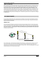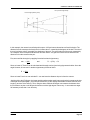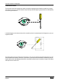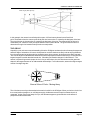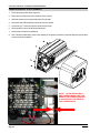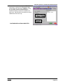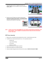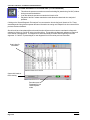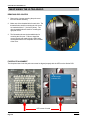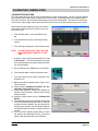
1
Service Manual
EEWA137A, EEWA544A, EEWA545A,
EEWA546A, EEWA550A, EEWA712A,
EEWA714AL
WHEEL ALIGNER
APRIL 2005
All information contained or disclosed in this document
is considered confidential and proprietary by Snap-on
Tools Company. All manufacturing, use, reproduction,
and sales rights are reserved by Snap-on Tools
Company and the information contained herein shall
not be used in whole or in part without the express
written consent of Snap-on Tools Company.
SNAP-ON® is a registered trademark of Snap-on Incorporated.
TABLE OF CONTENTS
Table of Contents
INTRODUCTION
GENERAL .......................................................................................................................................................... I
ALIGNMENT FUNCTIONS ................................................................................................................................ I
PREFERENCE FUNCTIONS ............................................................................................................................ II
MAINTENANCE MENU ................................................................................................................................... III
TOOLBAR ....................................................................................................................................................... IV
SOFTWARE FEATURES ................................................................................................................................. V
IMPORTANT SAFETY INSTRUCTIONS ......................................................................................................... VI
CHAPTER 1 AC/DC POWER DISTRIBUTION
ELECTRICAL SAFETY PRECAUTIONS ......................................................................................................
HANDLING STATIC SENSITIVE PCB’S .......................................................................................................
SERVICE GUIDELINES ................................................................................................................................
LOCKOUT AND/OR TAGOUT SYSTEM PROCEDURE ...............................................................................
AC THEORY OF OPERATION ......................................................................................................................
AC DISTRIBUTION .......................................................................................................................................
D.C.THEORY OF OPERATION ....................................................................................................................
POWER SUPPLY ...................................................................................................................................
HUB BOARD ..........................................................................................................................................
CAMERA POD ASSEMBLY ....................................................................................................................
1-1
1-1
1-2
1-2
1-3
1-3
1-3
1-3
1-4
1-5
CHAPTER 2 THEORY OF OPERATION
GENERAL ..................................................................................................................................................... 2-1
CAMERAS .............................................................................................................................................. 2-1
TARGETS ............................................................................................................................................... 2-3
TARGET ACQUISTION .......................................................................................................................... 2-4
3D VISION THEORY ..................................................................................................................................... 2-4
PERSPECTIVE ....................................................................................................................................... 2-4
FORESHORTENING .............................................................................................................................. 2-6
THE CIRCLE .......................................................................................................................................... 2-7
POSITIONING SEQUENCE ................................................................................................................... 2-9
SIDE-TO-SIDE DETERMINATION ....................................................................................................... 2-10
RELATIVE CAMERA POSITIONING (RCP) .......................................................................................... 2-11
THE FIXTURE ....................................................................................................................................... 2-11
MODELING THE VEHICLE IN 3-DIMENSIONAL SPACE .................................................................... 2-14
MEASURING STEERING ANGLES ..................................................................................................... 2-14
Effective
04/2005
TABLE OF CONTENTS
CHAPTER 3 CHECKOUT, CALIBRATION AND MAINTENANCE
TROUBLESHOOTING THE SYSTEM .................................................................................................... 3-1
GUIDELINES .......................................................................................................................................... 3-1
PC ACCESS ........................................................................................................................................... 3-2
BACK PANEL ......................................................................................................................................... 3-3
PC HOOKUP .......................................................................................................................................... 3-3
CAMERA REMOVAL & REPLACEMENT ............................................................................................... 3-4
HUB PCB REMOVAL & REPLACEMENT .............................................................................................. 3-5
ALIGNMENT SOFTWARE INSTALLATION .................................................................................................. 3-6
SPECIFICATION INSTALLATION ........................................................................................................ 3-10
PLATINUM SOFTWARE INSTALLATION ............................................................................................ 3-14
VOICEALIGN™ SOFTWARE INSTALLATION ..................................................................................... 3-16
MAINTENANCE MENU .............................................................................................................................. 3-18
CALIBRATION ...................................................................................................................................... 3-19
TID ................................................................................................................................................. 3-20
TARGET ID PROCESS .................................................................................................................. 3-20
RELATIVE CAMERA POSITIONING (RCP)................................................................................... 3-24
ACTIVATE AND CALIBRATE THE RIDE HEIGHT MEASURING DEVICE .................................... 3-27
CAMERA IDENTIFICATION ........................................................................................................... 3-29
CALIBRATION AND PREFERENCE BACKUP .............................................................................. 3-30
DIAGNOSTICS ..................................................................................................................................... 3-31
CAMERA VIEW .............................................................................................................................. 3-32
DATA EXAMINATION ..................................................................................................................... 3-33
CODES LIKELY TO APPEAR ON AN DATA EXAMINATION SCREEN ......................................... 3-34
CAMERA TEST .............................................................................................................................. 3-35
RACK CHECK ................................................................................................................................ 3-36
STORED DATA VIEWING TOOLS ....................................................................................................... 3-37
STORED IMAGE ANALYSIS .......................................................................................................... 3-37
STORED DIAGNOSTIC FILE ANALYSIS (3.3 OR GREATER) ...................................................... 3-38
EXPORT DIAGNOSTIC FILES (3.3 OR GREATER) ..................................................................... 3-40
WINDOWS UTILITIES ......................................................................................................................... 3-41
COVERING THE BASICS .................................................................................................................... 3-42
CSR PREFERENCES ................................................................................................................................. 3-43
STEPS FOR CHANGING PRAMETERS ....................................................................................... 3-43
TID PREFERENCES ...................................................................................................................... 3-44
PARAMETERS ............................................................................................................................... 3-45
TROUBLESHOOTING THE SYSTEM ........................................................................................................ 3-46
USB BASICS ........................................................................................................................................ 3-48
CAMERA TROUBLESHOOTING ......................................................................................................... 3-49
OTHER USB DEVICE TROUBLESHOOTING PROCEDURES ........................................................... 3-49
CHAPTER 4 SECURITY
GENERAL .....................................................................................................................................................
SECURITY KEY DISK ............................................................................................................................
BRAND SPECIFIC ..................................................................................................................................
SPECIFICATIONS ..................................................................................................................................
SOFTWARE FEATURES .......................................................................................................................
DESIGNATED CAMERA ........................................................................................................................
4-1
4-1
4-1
4-1
4-2
4-2
Effective
04/2005
TABLE OF CONTENTS
CHAPTER 5 ULTRA ARAGO 3™
GENERAL ..................................................................................................................................................... 5-1
COMPONENT IDENTIFICATION ........................................................................................................... 5-2
COMMON POD ASSEMBLY (SIDE VIEW) ................................................................................................... 5-3
LEFT CAMERA ASSEMBLY .......................................................................................................................... 5-4
FRONT VIEW ......................................................................................................................................... 5-4
REAR VIEW ........................................................................................................................................... 5-4
RIGHT CAMERA ASSEMBLY ....................................................................................................................... 5-5
FRONT VIEW ......................................................................................................................................... 5-5
REAR VIEW ........................................................................................................................................... 5-5
MAINTAINING THE ULTRA ARAGO ............................................................................................................. 5-6
REMOVING POD COVERS ................................................................................................................... 5-6
FACEPLATE ALIGNMENT ..................................................................................................................... 5-6
CAMERA REPLACEMENT ..................................................................................................................... 5-7
MOTOR DRIVE REPLACEMENT .......................................................................................................... 5-7
STROBE BOARD REPLACEMENT ....................................................................................................... 5-8
BOTTOM / TOP SWITCH REPLACEMENT ........................................................................................... 5-8
LOWER MINI HUB REPLACEMENT ..................................................................................................... 5-9
UPPER MINI HUB REPLACEMENT ...................................................................................................... 5-9
NORMAL WEAR ................................................................................................................................... 5-10
POWER SUPPLY ADJUSTMENT ........................................................................................................ 5-10
MOTOR CONTROLLER PCB JUMPER ............................................................................................... 5-10
CALIBRATING CAMERA PODS .................................................................................................................. 5-11
CALIBRATE POD MOTORS .................................................................................................................. 5-11
SELECTING THE WHEEL CLAMP TYPE ............................................................................................ 5-12
CAMERA POD ROTATION ................................................................................................................... 5-13
Effective
04/2005
TABLE OF CONTENTS
Effective
04/2005
INTRODUCTION
GENERAL
The contents of this service manual does not outline and explain the entire functions and use of the aligner. In
order for the Service Technician to properly troubleshoot and diagnose problems with this system he/she must
have an understanding of the proper operation of this unit and indicators. The 3D Image Aligner is a revolutionary concept in performing wheel alignments. The system uses a camera based machine vision technology
that provides many benefits to the shop owner and alignment technicians. It is the fastest, most accurate, and
easiest to use aligner ever made. One of the benefits of new technologies is the use of state-of-the-art components and computer programming that makes the task of servicing this product easier than previous generations of alignment equipment. One of the most obvious differences is the lack of an electronic measuring
head, the source of many of the failures and inaccuracies on conventional products.
The “eyes” of the vision-based 3D Aligner are the two cameras mounted on either end of a camera beam. The
proprietary design lens is for this usage, and is permanently mounted to the camera and triple-sealed for
protection. The camera also has a band-pass filter, limiting the spectrum of light that can enter the lens. With
any camera there is an optical “field of view” that is a characteristic of the lens design. Anyone who has used
a camera knows that what you see is what you get no more, no less. The cameras on the 3D Aligner are no
different.
This unit incorporates many security features that totally eliminates unauthorized use of the software. Once
the software has been successfully loaded the unit disables the “Key Disk” leaving them useless on other
units. The unit transfers the information from the “Key Disk” to the CAMERA PCB’s that in turn transfers it to
the hard drive. This information is stored in both locations. If for any reason the unit requires that the software
be reloaded, it uses the information from the CAMERA PCB that was taken from the “Key Disk” on the initial
loading process.
ALIGNMENT FUNCTIONS
The main menu of the aligner is the control center for the unit. It offers the operator easy control of the basic
alignment features. Moving the mouse pointer over the icon gives the operator a short description of the icon
function. See the operators manual for a more detailed list and
description of the many features and functions of the aligner.
Run Wizard - Steps the operator through a complete alignment. The alignment machine offers
many factory default wizards that can be edited by
the operator to either add or delete certain steps.
Vehicle Selection - Allows the operator to
select a particular vehicle for an alignment.
This selection can be made at any point
in the alignment by clicking on the
“Home” icon and selecting the “Vehicle
Selection” icon.
Vehicle Specification - Allows the operator to view the specifications for the vehicle chosen
from the vehicle selection icon. The operator has the ability to edit the specifications and save
the edit specification to a custom specification database.
Effective
04/2005
Page i
INTRODUCTION
Inspection - Offers a variety of inspection menu allowing the operator to perform predetermined inspections. Six Inspection screen are available under Inspections as well as a Diagnostics icon. These are Pre-Alignment Inspection, Tire Inspection, Brake Inspection, Under Car
Inspection, Under Hood Inspection, and Courtesy Inspection.
Measurement - Offers quick access to several angular measurement screens such as Caster,
SAI, Steering Angles, and Vehicle Dimensions.
Adjustment - Offers access to a variety of features that assist the technician with adjustment of
alignment angles. Some of these features include Live Caster, A-Arm Adjust, Rear Shim
Programs, and Cradle Adjust.
Customer Data - Offers the operator easy control for finding, adding or editing any customer
data that has been previously saved from past alignments. Information can then be retrieved
and sorted through a myriad of different options.
PREFERENCE FUNCTIONS
User Interaction - Gives the operator control of
“Features”, “Displays”, “User Login” and “Security.
Units of Measure - Allows the operator to control
the way the unit displays alignment measurements.
CSR Preferences - This is a secure location
for technical personnel only. Allows a field
technician to overide any security that
may have been entered by the operator.
Connectivy - Protocall options for
various alignment options.
System Configuration - Select either
two or three camera system.
Select Wizard - Allows the operator to
select any default alignment wizard or
access to customize wizards to meet
their specific alignment option needs.
Store Name - Allows the operator to
input specific store information to be
used on printouts.
Regional Settings - Allows the operator to choose screen language and an
alternate language (if installed). Also
allows access to different spec databases.
Page ii
Effective
04/2005
INTRODUCTION
MAINTENANCE MENU
General Maintenance for the Ultra system is performed using this Maintenance Menu. Always check the
current revision of software before calling technical support for assistance, as Maintenance Menus and icons
are subject to change.
Calibration - Software used
to perform several calibration
procedures including TID,
Camera Aim, Hub Pin ID,
RCP, and RCP Check.
Diagnostic - Several diagnostic procedures used to
troubleshoot different parts of
the system including Camera
View, Camera Check, IVS
Processing Test and Target
Check.
Preventative Maintenance – Software feature
that guides the equipment operator through recommended periodic aligner maintenance.
(See Operators Manual for details)
Demo Mode - A program used primarily by sales representatives and training personnel.
This is a program that demonstrates the capabilities of the aligner software without actually
having a vehicle available. It is a useful tool for training new or experienced users about
machine features. (See Operators Manual for details)
Windows Utilities – Allows access to the Windows Desktop and also allows the operator to
perform routine installation of printers, software, etc. See “Windows Utilities” for details.
Database Utilities – The feature is used for backing up and restoring alignment based data
files, customer data, etc. (See Operators Manual for details)
Speaker Training – Optional Hardware / Software package that allows and end-user to
control the aligner through voice commands. (See Operators Manual for details)
Effective
04/2005
Page iii
INTRODUCTION
TOOLBAR
The toolbar is a series of buttons at the top of each
alignment screen. The toolbar is interactive and
changes with each screen depending on the location
within the software. Each button and an explanation
of it’s use can be found in the operators manual,
however some will be pointed out in this manual.
Moving the pointing device over each button will
give the operator a quick overview of the button. If a
button is active it will be displayed in full color,
however if the button is not active it will not be
highlighed
Alignment Help - Opens the operators
guide within Adobe Acrobat.
Regional Settings - Allows the operator to
quickly changes between Languages and
Specification databases.
Meter Screen - Jumps to the Alignment
reading screen.
Wizard - Allows the operator to choose from
several standard alignment wizards or
customize his/her own.
Home - This button can be found on all
toolbars, this enables the operator to jump
back to the Main Menu.
Log In/Out - Allows the operator the
capability to set up an unlimited amount of
custom users for the aligner.
Print - Enables the operator to immediately access the print menu.
MKS - Merecedes Benz “MKS” system.
Only available with Mercedes Software.
Logo Screen - Takes the operator to the
Logo Screen
About - Displays the current software and
alignment vehicle database revisions.
Shop Management - Runs the Shop
Management Program if purchased
(Optional)
Information Systems - Runs the Mitchell
Program if purchased (Optional)
Page iv
Effective
04/2005
INTRODUCTION
SOFTWARE FEATURES
All Models
• Live Vehicle Dimensions n
• Equalize Toe Warning Unique!
• Adjust Front Before Rear Warning Unique!
• Enhanced Printouts
• Voice driven alignment.
• Customer database backup and restore
• V3D/CCD Sensor Switching
• Enhanced Manual Ride Height Measurement Screens o
• Backup and Restore of Calibration and Setup Data
• Changeable Readings in Demo Mode
• Enhanced Ford Bushing Program Unique!
• NorthStar Shim Program Update
• Updated PDF Operator Manuals
• Updated Worldwide Translations
• Proper Shutdown Button Operation
CCD Models Only
• Enhanced Sensor Diagnostics
Imaging Models Only
• Rolling Radius Auto Advance
• 2-wheel Alignment (2 & 4 Target) Unique!
• Caster Trail, Scrub Radius, SAI & Included Angle Measurement Screen
• Automated Ride Height Measurement o p Unique!
• Illumination LED Management
o
Unique!
Note:
n Excludes Entry Level models
o Platinum software only
p Requires accessory purchase
Effective
04/2005
Page v
INTRODUCTION
IMPORTANT SAFETY INSTRUCTIONS
When using this equipment, basic safety precautions should always be followed,
including the following:
1.
Read all instructions.
2.
Do not operate equipment with a damaged power cord or if the equipment has been
damaged until it has been examined by a qualified authorized service technician.
3.
If an extension cord is used, a cord with a current rating equal to or more than that
of the machine should be used. Cords rated for less current than the equipment
may overheat. Care should be taken to arrange the cord so that it will not be tripped
over or pulled.
4.
Always unplug equipment from electrical outlet when not in use. Never use the
cord to pull the plug from the outlet. Grasp plug and pull to disconnect.
5.
To reduce the risk of fire, do not operate equipment in the vicinity of open
containers of flammable liquids (gasoline).
6.
Keep hair, loose fitting clothing, fingers and all parts of the body away from moving
parts.
7.
Adequate ventilation should be provided when working on operating internal
combustion engines.
8.
To reduce the risk of electric shock, do not use on wet surfaces or expose to rain.
9.
Do not allow unauthorized personnel to operate the equipment.
10. Use only as described in this manual. Use only manufacturer’s recommended
attachments.
11. ALWAYS WEAR SAFETY GLASSES. Everyday eyeglasses only have impact
resistant lenses, they are NOT safety glasses.
SAVE THESE INSTRUCTIONS
Page vi
Effective
04/2005
CHAPTER 1
AC/DC POWER DISTRIBUTION
ELECTRICAL SAFETY PRECAUTIONS
Make sure the aligner is unplugged before disconnecting any wires in preparation for replacing any boards,
cables or other items within the unit. Use the “Lockout and/or Tagout” procedure.
When working on this aligner, keep three points in mind:
!
THIS UNIT MUST BE PLUGGED IN TO A PROPER AC OUTLET FOR THE
UNIT TO OPERATE CORRECTLY. REFER TO THE UNIT ID PLATE LOCATED ON THE BACK OF THE UNIT. EXTENSION CORDS ARE NOT
RECOMMENDED, BUT IF AN EXTENSION CORD MUST BE USED, USE A
CORD THAT IS LESS THAN 50 FEET WITH A 16 AWG, OR ABOVE 50
FEET AND LESS THAN 100 WITH A 14 AWG.
1
Aligner voltages refer to the “return” (white) side of the AC line. Yet sometimes outlet wiring is reversed. In
that case, electrical neutral connects to the “hot” side of the line. The aligner operates normally, but the PC
board floats 110 VAC above safety ground. Assume that points inside the aligner console are at
110VAC; observe all safety precautions. If you make measurements with grounded test equipment, use an
isolation transformer. An oscilloscope is an example of such test equipment.
The aligner is susceptible to power line spikes and noise. You must connect the equipment to safety
ground. Does your machine do “strange things” or exhibit intermittent problems? Check for a proper
ground at the machine and the power outlet. If you’re using an extension cord, check that, too. It must be
constructed of at least 16 gauge wire and under 50 feet long.
Schematic voltages refer to the “return” side of the line, not safety ground. When measuring AC voltages,
use the white wire on the line power terminal block as ground. Don’t use the third, center safety ground
terminal. Another place to access ground is at the shield. The black wire in the shielded transducer cables
also connects to the ground return.
2
3
HANDLING STATIC SENSITIVE PCB’S
Electrostatic discharge can destroy high impedance ICs if uncontrolled. Use the following techniques to avoid damaging ICs:
-
Leave new circuit boards in their antistatic bags until ready for use.
When replacing boards, proms, etc. be sure to turn off power to the machine first
Use an anti-static wrist strap. Connect it to chassis ground on the equipment or to an available raw ground.
Touch the chassis of the equipment to put yourself at the same static potential as the equipment.
Grasp the PCB from opposite sides using your fingertips. Do not grasp the components on the board.
!
USE STANDARD ANT-STATIC PROCEDURES
WHILE PERFORMING THESE INSTRUCTIONS
Effective
04/2005
Page 1-1
CHAPTER 1 AC/DC POWER DISTRIBUTION
When inserting PCB’s:
- Place boards on a grounded static mat after removal.
- Remove the new PCB from the original package onto a grounded static mat. Save packaging to use when
returning defective boards.
- Remove power from the machine (un-plug from wall) before installing the PCB.
- Avoid handling components needlessly.
- Do not set PCBs on insulating surfaces such as paper, glass, rubber, or plastic.
- Static is generated by friction. The following actions promote static generation:
- Wearing silk or nylon clothing.
- Walking on carpets.
- Walking with rubber soled shoes.
Static generation is increased when certain environmental conditions exist. Conditions of low humidity combined with wearing silks or nylons, walking on carpets, or walking with rubber soled shoes may create large
electrostatic charges on your person, capable of blowing a hole in the substrate of an IC.
SERVICE GUIDELINES
-
BEFORE REPLACING circuit boards, verify that the main power supply operates within specifications.
VERIFY that board connectors are fully seated.
NEVER remove boards or disconnect a connector with the power on!
MAKE SURE that you completely understand what the aligner does. (If it works, you can’t fix it!) Refer to
the Aligner Operator’s Manual, application notes, and flow diagrams.
BE CAREFUL when handling circuit boards! Wear an anti-static wrist strap.
WHEN TRANSPORTING circuit boards, use anti-static bags.
NOTE:
RELATIVE HUMIDITY HAS A DIRECT EFFECT ON STATIC CHARGE BUILDUP. AS HUMIDITY
DECREASES, STATIC BUILDUP USUALLY INCREASES.
LOCKOUT AND/OR TAGOUT SYSTEM PROCEDURE
1. Notify all affected employees that a lockout or tagout system is going to be utilized and the reason thereof.
The authorized employee shall know the type and magnitude of energy that the machine or equipment
utilized and shall understand the hazards thereof.
2. If the machine or equipment is operating, shut it down by the normal stopping procedure (depress the stop
button, open toggle switch, etc.)
3. Operate the switch, valve, or other energy isolating device(s) so that the equipment is isolated from its
energy source(s). Stored energy (such as that in springs, elevated machine members, rotating flywheels,
hydraulic systems, and air gas, steam or water pressure, etc.) must be dissipated or restrained by methods such as repositioning, blocking, bleeding down, etc.
4. Lockout and/or tagout the energy isolating devices with individual lock(s) or tag(s).
5. After ensuring that no personnel are exposed, and as a check on having disconnected the energy sources,
operate the push button or other normal operating controls to make certain the equipment will not operate.
CAUTION: RETURN OPERATING CONTROL(S) TO “NEUTRAL” OR “OFF” POSITION AFTER THE
TEST [DE-ENERGIZED STATE].
6. The equipment is now locked out or tagged out.
Page 1-2
Effective
04/2005
CHAPTER 1 AC/DC POWER DISTRIBUTION
AC THEORY OF OPERATION
Always use “one hand rule” when working with AC voltages by keeping one hand in your pocket or behind your
back. Before removing any wires on the equipment, always verify that the equipment is turned “OFF”. Turn off
the Main Power switch in the back of the unit and unplug the AC power cord from the AC outlet.
!
DANGEROUS HIGH VOLTAGES
ARE PRESENT IN THIS EQUIPMENT
AC DISTRIBUTION
Alignment Console primary voltage is 110VAC, 60Hz via the hot side (black wire) of the AC power cord. On the
Alignment console the power comes to a power strip then is distributed to the Monitor, Printer, and if so
equipped the battery charger for voice control module. For the camera power supply box, the power comes via
the hot side (black wire) of the AC power cord to an EMI filter to a on/off switch then to the power supplies.
D.C.THEORY OF OPERATION
POWER SUPPLY
The power supply is a COSEL LEB100F-0512. The output voltage of the power supply is +5V 5A and +12V 5
(Peak 10) A. The power supply is used to supply the camera with 5 volts to run the wheel indicator LED’s and
the 12 volts is used to run the strobe LED’s. The output connector on the power supply is labeled as V1 and
V2. V1 is the 5 volt line and V2 is the 12 volt line. Each output voltage has it’s own separate ground. When
measuring the output voltage of the power supply the technician must attach the leads of the VOM to the
appropriate ground to receive back the correct voltage. Failure to connect the VOM to the correct pins will result
in a incorrect voltage reading and may cause the technician to prematurely replace a good power supply.
AC Input CN1
1 = AC (L) (White)
2 = AC (N) (Blu)
3 = GND (Blk)
DC Output CN2
V1 = 5VDC (Red)
G1 = 5VGND (Blk)
V2 = 12VDC (White)
G2 = 12VGND (Green)
To back of cabinet
Effective
04/2005
Page 1-3
CHAPTER 1 AC/DC POWER DISTRIBUTION
The DC output of the Camera Power supply feeds through a harness on the back of the cabinet. Both the 5V
and 12V power is fused at this location. Should a camera stop working checks should be made to both fuses
for proper continuity and both the 5V and 12V be checked for proper power using a VOM.
From PC USB
From Power
Supply
HUB BOARD
The HUB board is housed inside an aluminum extrusion behind the camera beam. The HUB board’s purpose is
to pass information to and from each of the camera’s directly to one of the USB Ports on the back of the PC.
The HUB board has 4 USB connectors for either a two camera system or a three camera system. The Db9
connector at the bottom of the HUB Board is a direct link to the PC, the other 3 connections are equivalent for
the camera’s, any camera will plug into any of the three camera connections. There is also a Db15 connector
on the HUB Board for future motor control.
Camera USB
Camera USB
Camera Pwr.
Camera Pwr.
To PC USB
Camera USB
Incoming
Camera Pwr.
Camera Pwr.
Motor Control
Page 1-4
Effective
04/2005
CHAPTER 1 AC/DC POWER DISTRIBUTION
CAMERA POD ASSEMBLY
When ordered the camera pod comes as an assembly however should a strobe board fail it can be ordered and
replaced separately. The camera pod is supplied with both 5VDC to power the “Acquired target indicators” and
directional LED’s and 12VDC to power the strobe.
Camera Board
Camera
USB
Strobe Board
Camera
Power
The strobe is held on the camera pod assembly with 4 screws and lockwashers. By viewing the LED’s on the
strobe board the technician should be able to quickly identify if both the 5VDC and 12VDC are present. There
are no test points available. In the figure below all Target Indicators and Directional Indicators are lit up.
Each of these LED’s require 5VDC to light these LED’s with the exception of the Strobe ON indicator it uses
12VDC. The strobe LED’s are infared and appear to be off during the alignment process however this Strobe
ON LED indicator was added to the strobe board to alert the technician or alignment technician that the strobe
LED’s are firing. This LED is located behind the intuitive cover and is not visible to the operator however it can
be seen by looking closely.
Roll
Directional
Indicators
Strobe ON
Indicator
Target
Not Acquired
Indicators
Caster
Directional
Indicators
Target
Not Acquired
Indicators
Effective
04/2005
Page 1-5
CHAPTER 1 AC/DC POWER DISTRIBUTION
When the targets have been mounted to the wheel and tire of the vehicle the Target Indicator LED’s will illuminate green once the targets have been acquired.
Target
Acquired
Indicators
Target
Acquired
Indicators
Page 1-6
Effective
04/2005
EEWA546A
Rod Harrison
04/2004 REV B.
Eric Bryan
ULTRA Block Diagram
1-1
1-7/8
Page left blank intentionally
CHAPTER 2
THEORY OF OPERATION
GENERAL
The 3D Image Aligner is a revolutionary concept in performing wheel alignments. The system uses a camera
based machine vision technology that provides many benefits to the shop owner and alignment technicians. It is
the fastest, most accurate, and easiest to use aligner ever made. One of the benefits to new technologies is the
use of state-of-the-art components and computer programming that makes the task of servicing this product
easier than previous generations of alignment equipment. One of the most obvious differences is the lack of an
electronic measuring head, the source of many of the failures and inaccuracies on conventional products. There
is not much about this aligner that is conventional.
Shop owners and alignment technicians easily recognize the many strengths of this system compared to
conventional measuring-head systems. As the 3D Aligner was prepared for introduction into other International
markets such as Asia and Latin America, it became evident that the tasks of developing language translations
and market-specific vehicle specification databases was overwhelming with DOS. The decision was made in
1998 to develop a Windows-based user interface for the 3D aligner in parallel with efforts to do the same for the
company’s conventional wheel alignment system. In the fall of 1998, the Windows environment was introduced.
The Windows compliant Pro32 software has a robust set of features, adds the familiarity and power of Windows,
and has 27 different languages and 13 different specification databases. In addition, Windows offers powerful
networking capabilities that will gain in importance as the automotive service industry discovers the benefits of
information sharing between the front point-of-sale counter and the back shop.
CAMERAS
The “eyes” of the vision-based 3D Aligner are the two cameras mounted on either end of a camera beam. The
cameras are high-resolution CCD video type operating in gray-scale, similar to those used in security and
surveillance applications. The proprietary design lens is for this usage, and is permanently mounted to the
camera and triple-sealed for protection. The camera also has a band-pass filter, limiting the spectrum of light
that can enter the lens. With any camera there is an optical “field of view” that is a characteristic of the lens
design. Anyone who has used a camera knows that what you see is what you get no more, no less. The
cameras on the 3D Aligner are no different.
The field of view (Figure 2-1 / 2-2) is located along each side of the alignment rack and is a cone-shaped “tunnel”
that expands in size as it moves further away from the cameras. The tunnel is approximately 2½ feet in
diameter near the front turntables. The centerlines of the tunnels are close to vehicle spindle height and about 18
inches outside of the outer wheel surface of an average car. In fact, the cameras are initially aimed at the
factory so that the targets, when mounted onto an average vehicle, would be located in the center of that tunnel.
This insures that any vehicle placed on the rack in front of the 3D Aligner, from the widest to the narrowest, will
have the targets mounted within the cameras’ field of view.
Effective
04/2005
Page 2-1
CHAPTER 2 THEORY OF OPERATION
Side Field of View
Figure 2-1
Top Field of View
Figure 2-2
The Strobe Board contains 80 infared LED’s in an array to provide a source of bright light to reflect off the
targets when camera images are taken. These LED’s are rated for 100,000 hours continuous operation, and up
to 50% of the LED’s can fail without affecting the cameras ability to see the targets. These infared LED’s are
synchronized with the cameras so an image is “captured” every time the lights flash (roughly 2 times per
second).
Page 2-2
Effective
04/2005
CHAPTER 2 THEORY OF OPERATION
TARGETS
The target’s visual surface is a series of circles or “dots” made of a retroreflective material. This material returns
any light that hits its surface at a 180-degree angle directly back towards the source. If we are looking at the
reflected light, it is brightest at the center of the light source. As we move away from the source the brightness
of the light diminishes rapidly. Street signs have retroreflection material on certain parts of their surface. This
material reflects light from a vehicle’s headlights back to the motorist’s eyes. The portion of the sign that traffic
control wants the driver to pay attention to is reflective, while the rest of the sign fades into darkness. Drivers in
other cars cannot see the reflected light from the headlights of other cars because the angle of view is too large.
In the case of the 3D Aligner, light is generated by the LED’s, hits the target, and returns along the same path to
the camera when placed in the center of the LED array.
The retroreflection material is placed on an aluminum backing plate to insure the reflective pattern remains flat.
This assembly is then mounted into a hard ABS plastic housing for shock and damage protection. Finally, a
special piece of tempered glass is placed on top of the retroreflection material for final protection from damage.
The top glass is special for two reasons. First, it is an “optical grade” glass that is free of imperfections and
impurities. This is necessary so the reflected image the cameras see is not altered by glass imperfections.
Second, the backside of the glass contains a pattern of “dots” etched from a jet-black emulsion material. This
dot pattern created by the glass allows the cameras to see a very unique item that the 3D Aligner recognizes.
The various dimensions of this pattern of dots is a known quantity that is stored within the program and is used
as a constant, forming the basis of our vision-based measuring system.
There are 33 dots on each target laid out in a very distinct manner. A great deal
of time and effort was placed on designing this pattern of dots. In some ways the
dots appear to be randomly placed, but in other ways appear to have some
symmetry. Some of the dots are larger than other dots, and there is even one dot
that is a “donut”. It must be noted that these circles we see are geometrically the
“roundest” circles we will ever encounter this is necessary for the interpretation of
angles, as we will learn later. Note also that the dots on the rear targets are larger
than the front targets to allow vision at a further distance.
Since the engineers designed the target dot pattern with great precision, they know the exact dimensions of
each dot and the distance from any one dot to another. It is possible then to create a computer model of this
pattern that the 3D Aligner software could use as it looked at camera images. This would be usable in the
program only if we were certain that the target attached to the vehicle matched the computer model. Since it is
impractical to have an engineer hand-make each target to the required precision, a detailed manufacturing
process was created to make sure each target was an exact duplicate of the original design.
Effective
04/2005
Page 2-3
CHAPTER 2 THEORY OF OPERATION
TARGET ACQUISTION
When we begin a new alignment the program has no idea where the targets are located. The software turns on
the cameras and goes into a “search mode”, looking throughout the cameras’ field of view for any targets. We
see this on the screen in the form of 4 red targets away from the wheels. Since the software knows what a
target looks like, when it sees an object that may be a target it applies what is called a “fit algorithm” – how
closely does that object match what it knows to be a target. In this way, objects that are not targets (such as
reflective lamps on the vehicle) are ignored. As each target is found and fitted (or acquired) it turns blue on the
screen and appears attached to the wheel. When a target is acquired the software “hones in” on that region of
the camera view ignoring activity in the background. This allows the system to be more responsive to changes
in target position.
3D VISION THEORY
From the previous discussions of the components of the 3D Aligner we have a basic understanding of how the
hardware system functions. But how does the software take these camera images of target dots and interpret
them as wheel alignment angles?
PERSPECTIVE
One of the things the 3D Aligner must determine is how far away each target is from the cameras at any given
moment. As everyone knows, objects appear to get smaller as the move farther away, even though their actual
size remains the same. If you look at a screwdriver 2 feet away from you it looks much larger than it does at 20
feet away. This effect is called perspective. Artists create the illusion of depth and distance in two-dimensional
drawings using this technique.
S c re
w d ri
ve r V
ie w e
d Si
ze
6"
Distance from Eye
In the example above, assume that the screwdriver is 6 inches long. If you had a way to “measure” the exact
size of the screwdriver your eye sees at some distance away, through the application of high school level
mathematics you can determine how far the screwdriver is from your eye. On the following page there is a more
detailed explanation of the mathematical principles.
Page 2-4
Effective
04/2005
CHAPTER 2 THEORY OF OPERATION
Pen (known length fixed)
Focal Length (fixed by lens)
In this example, the camera is at a fixed point in space. All fixed camera lenses have a fixed focal point. The
distance from the camera to the focal point is a known value F, created by the designers of the lens. The size of
the pen is a known value P, created by the designers of the pen. The perceived size of the pen is measured by
our “software” at the focal point and becomes a known value A. The goal of this exercise is to determine the
distance D from the camera to the pen.
First, we must find the angle r by applying formulas from basic trigonometry:
tan r = (A/2)
and
Z2 = (P/2)2 + D2
F
Since we know A,F,P and Z can be calculated and the angle can be found using trigonometric tables. Once the
angle is known, we can use it in another trigonometry formula to find D:
D = (P/2)
tan r
Since we know P and r we can calculate D – we now know the distance the pen is from the camera.
Applying this to the 3D Aligner, the image analysis software takes each image and precisely measures the size
of each dot on the photograph – this is the perceived size (A). We already discussed the known values of focal
length (F) and size of the dots (P). Thus, using the above math the 3D Aligner can measure the distance from
the cameras to any dot on the targets and can do so with a high degree of accuracy – it can measure a target
20 feet away to less than 1 mm accuracy.
Effective
04/2005
Page 2-5
CHAPTER 2 THEORY OF OPERATION
FORESHORTENING
The discussion earlier about perspective and the screwdriver example assumed that the screwdriver (or target)
was “normal” to your eye. Normal means the object is being viewed straight on (perpendicular or at 90 degrees),
so its full length is observed.
90o
Look what happens to the observed size of the screwdriver when it is rotated away from 90 degrees to your eye–
it appears smaller.
The observed size of the screwdriver becomes shorter. The more it is rotated, the smaller it appears to be. This
effect is called foreshortening. As before, if you know the actual size of the screwdriver is 6 inches, by measuring the observed size and applying mathematics it is possible to determine the screwdriver’s angle of orientation
with respect to the normal view.
Page 2-6
Effective
04/2005
CHAPTER 2 THEORY OF OPERATION
Pen (known length fixed)
Focal Length (fixed by lens)
In this example, the camera is at a fixed point in space. All fixed camera lenses have a fixed focal
point. The distance from the camera to the focal point is a known value F, created by the designers of the lens.
The size of the pen is a known value P, created by the designers of the pen. The observed size of the pen is
measured by our “software” at the focal point and becomes a known value B. The goal of this exercise is to
determine the angle of orientation R away from the normal position.
THE CIRCLE
Hopefully by now we have some understanding of how the 3D Aligner can determine how far away the targets are
and their angle of orientation. Of course, when placed on a vehicle the dots are likely to be at varying distances
from the cameras and at varying angles or orientation at any given moment. An observer to the above may ask,
“how can the aligner tell the difference between the effects of perspective and foreshortening? All it knows is the
targets images are smaller than their actual size. What about orientation changes in 3 dimensions?”. The
answer is a powerful geometric shape, the circle. As you will find out, the circle was chosen as the geometric
shape for the targets because of its mathematical relationships. For this discussion, assume the aligner targets
consist of a single large dot.
Y
X
Normal View of Circle - Moving Away
The circle has some unique characteristics that make it useful for the 3D Aligner. When you look at a circle from
the normal position (straight on, or a 90-degree angle), the diameter across is equal no matter where it is
measured. As the circle moves away from you, the diameters appear to get smaller due to the effects of
perspective as discussed earlier.
Effective
04/2005
Page 2-7
CHAPTER 2 THEORY OF OPERATION
Now look what happens as the circle is rotated about the X-axis – in two dimensions it appears to be an elliptical shape.
Y
Y
X
Rotated X
The more we rotate the circle about the x-axis, the smaller the y-axis diameter appears. In fact, a mathematical
relationship exists that says if you can measure the length of the y-axis line and the length of the x-axis (the
circle’s true diameter), you can determine the angle of rotation. To put this all together, no matter how you
rotate the circle in any dimension (X, Y, Z), the true diameter axis is always visible. This is called the ellipse’s
long axis. The 3D Aligner measures every diameter on the target dot and uses the long axis it finds as the true
diameter to determine how far away the target is through perspective. Then, it looks at the diameters in the
other dimensions that are 90 degrees to the true diameter to find the short axis and determines the angle of
orientation away from normal with foreshortening. Using these methods it determines where the target dot is in
three-dimensional space with respect to the camera, both distance and orientation. It is the circle’s unique
characteristics that allow the aligner to distinguish between the effects of perspective and orientation. Examine
below to see and example of a target rotated in different directions.
For this discussion we assumed the target has only one dot. In reality, each target has 33 dots (and there are 4
targets), and the 3D Aligner’s powerful computer system analyzes each circle simultaneously for incredible
accuracy and resolution. We have now seen how the aligner uses the camera images to determine the targets
location and orientation in 3-dimensional space. It now has the capability to measure, but how does it use
these principles to measure wheel alignment angles?
Page 2-8
Effective
04/2005
CHAPTER 2 THEORY OF OPERATION
POSITIONING SEQUENCE
The 3D Aligner knows where the targets are, but it does not yet know where the vehicle is. Of course, the
targets are attached to the vehicle’s wheels, and this provides the link to the vehicle’s alignment angles. The
term “wheel alignment” is a bit misleading. We don’t adjust the wheels, we adjust the suspension and steering
components, resulting in changes at the wheel. It is the vehicle “spindle” that receives the alignment, and the
wheels are just along for the ride. All wheel alignment equipment uses the spindle as a starting point, usually by
either placing the measuring device directly opposite the spindle or by performing a runout compensation
referencing gravity or the rack. The 3D Aligner finds the spindles in a unique way that improves accuracy and
speed.
Axis of
Rotation
A single point on the wheel/tire is represented by the star. If we rotate the wheel/tire and track the position of
the star at various points we would find the star movement forms a circle. If we determine the center of the circle
we have defined the axis of rotation of the wheel/tire. In automotive terms, the axis of rotation of the wheel is
called the spindle.
The 3D Aligner locates the vehicle spindles directly using a procedure called positioning. In positioning, we
rotate the wheel/tire/target by pushing the vehicle back. As the vehicle moves, the cameras track the location
and orientation of the target dots. If the wheel went through a complete 360-degree rotation each dot would
scribe a circle as illustrated in the picture below. If we took our scribed circle and determined where the center
of that circle was located, we would find the spindle. The dot moves back as well as rotating about the axis, this
allows the software to locate the spindle position in 3 dimensions with respect to the camera.
Of course there is more than one point on our targets that the cameras can track, there are 33 reflective dots.
As we move the car back, each dot is tracked for distance and orientation, with the software using this data to
Movement of a Point During Positioning
create 33 circles of different sizes. Each circle is then analyzed for the center point, with the results averaged to
determine the vehicle’s spindle. Since there is a target on each wheel the software finds each of the 4 spindles
simultaneously.
In the last paragraphs the positioning sequence described the targets dots scribing a circle through a 360degree rotation of the wheel. In reality, this is not practical a full wheel rotation would require a roll back of 5 to 7
feet, depending on the circumference of the tire. Most alignment racks cannot handle this. The engineers were
able to shorten the wheel rotation angle to 35-degrees + 5. This works out to 6 to 10 inches of roll back, which
is easy to accomplish with most vehicles.
Effective
04/2005
Page 2-9
CHAPTER 2 THEORY OF OPERATION
When the vehicle is rolled back, the 3D software directly locates the spindles and now knows 4 distinct points in
space with respect to the cameras that are part of the vehicle. Since the vehicle is now back off the rack
turntables, it is necessary to roll it forward to perform any corrections. The aligner uses the software when
rolling the vehicle forward as a check of the results of the roll back. As the operator moves the vehicle forward
we repeat the positioning sequence. When the vehicle returns to the turntables we have a new measurement of
spindle locations. The software then compares the results of the roll back with those of the roll forward; if they
agree, the program is satisfied and moves on; if they do not agree an error message appears called “Wheel
Wobble” and we are forced to repeat positioning until they agree. This is one of many examples of where the 3D
Aligner performs “quality checks” to insure the highest degree of accuracy possible.
SIDE-TO-SIDE DETERMINATION
The 3D Aligner gathers target images utilizing two cameras mounted on the ends of a beam. This beam is
positioned higher than the vehicle’s wheels to allow the cameras to see the rear targets (the front targets are
smaller, allowing easier viewing of the rear). Each camera can see a front and rear target on its side of the
vehicle, and thus determine their locations and orientations, and find the two spindles on that side. However,
each camera cannot see the targets on the other side of the vehicle. When determining alignment angles such
as thrust angle and setback, it is necessary to “connect” the vehicle sides, to know the relationship of the left
side to the right side. To do this, the 3D Aligner must know the positions of each camera with respect to one
another.
To get an idea of the type of analysis the 3D Aligner program must do. In the picture there is a vehicle with all
targets attached. The program can determine the distance from each camera to the front and rear targets on its
side of the vehicle as indicated by the check marks using perspective. What it cannot do directly is determine
the distance from the camera to the front and rear targets on the other side (question marks). The way to find
the cross-distance is to know the distance between the 2 cameras called “RCP” on the figure. If RCP is known
it is straightforward mathematics to determine the cross-distance in question since two sides of a right triangle
are known – Pythagorean Theorum: a2 + b2 = c2. But how does the program know the dimension RCP? We
must tell it!
RCP
3
3
Page 2-10
3
3
Effective
04/2005
CHAPTER 2 THEORY OF OPERATION
RELATIVE CAMERA POSITIONING (RCP)
It would be easy to say that we know the distance between the cameras because we designed and manufacture
the Camera Beam and cameras. However, the knowledge the aligner must have about the relationship of one
camera to another is critical and must be known to high level of precision – manufacturing tolerances in the
beam and camera assemblies are too variable to be counted on. When the aligner is installed the technician
mounts the cameras onto the beam. Later, the technician performs a camera aim in which he/she alters the
position of the cameras. Once all camera movements are completed it is time for us to help the program find
out where the cameras are with respect to each other. We must perform Relative Camera Positioning.
THE FIXTURE
The fixture used to perform RCP is also used for camera aiming. It consists essentially of a bar about 5.5 feet in
length with a target attached on each end (a front and rear). Stands are used to place it on the alignment rack,
which should be at alignment height so the targets are visible to the cameras.
Due to manufacturing tolerances and transportation of the fixture, we cannot be sure its dimensions are the
same as the design. We must measure it each time we perform RCP. Of course, we always have a highly
accurate measurement tool at our disposal – the 3D Aligner. To measure the length of the fixture we place the
assembly on the right runway of the rack in the view of the right camera.
RCP
3
3
3
The right camera measures the distance to the front target and the rear target, and subtracts the two with the
difference being the fixture length. This is stored in memory for usage later in the RCP procedure.
Effective
04/2005
Page 2-11
CHAPTER 2 THEORY OF OPERATION
To determine Relative Camera Position we need to take the fixture of a length we know and place it across the
runways, placing one target in the left camera’s vision and one target in the right camera’s vision.
3
RCP
3
3
3
RCP Step 2
The right camera measures the distance to the right target, the left camera measures the distance to the left
target, and the memory has the fixture length. We have 3 of the 4 sides of a trapezoid, and through application
of mathematics we can determine the fourth – RCP. We also recheck our calculations several times by placing
the fixture back on the runways at different points before proceeding.
Page 2-12
Effective
04/2005
CHAPTER 2 THEORY OF OPERATION
The RCP procedure establishes the missing dimension that allows side-to-side determination – each camera’s
position with respect to each other. The accuracy of this calculation is highly dependent on the fixture being
dimensionally stable as we move it from point to point on the rack. The final step is to recheck the fixture to
make sure it is the same length. We call this rechecking the fixture length.
We do this by placing the fixture on the left runway so that both targets are in the visual field of the left camera.
If we measure with one camera, then measure with a different camera and get the same values we can be sure
the fixture has remained stable and our RCP is valid.
3
RCP
3
3
3
If the final check reveals the fixture has changed dimensions during the process we are given notice and must
repeat the RCP procedure from the beginning. Because the Camera Beam is rigid, the cameras are hardmounted to the beam. And the structure is away from the action, the system does not require periodic maintenance calibration. The only way the accuracy of the RCP can be affected is if one camera moves with respect
to the other – not likely to happen in every day usage.
Effective
04/2005
Page 2-13
CHAPTER 2 THEORY OF OPERATION
MODELING THE VEHICLE IN 3-DIMENSIONAL SPACE
After Positioning is completed, and the program is able to relate one side of the vehicle to the other, the software
knows 4 distinct points that create a plane in space that are part of the vehicle. It takes these points and
creates a 3-dimensional model of the vehicle plane. From this model, all alignment angles, caster, SAI, camber,
and toe are referenced to the vehicle plane. This is in contrast to conventional measuring-head aligners that use
gravity or the rack surface as a reference. For this reason, the 3D Aligner does not rely on a level lift. In reality,
the aligner does not require gravity to measure, but our vehicle’s physical state will change radically in a weightless environment.
MEASURING STEERING ANGLES
The steering angles caster and SAI are defined by physical components of the vehicle suspension, those that
define the steering axis (such as upper and lower ball joints on a short-arm long-arm suspension). Conventional
aligners measure these angles using gravity gauges and the toe system by monitoring the affect these angles
have on those angles as the wheels turn. Once again the 3D Aligner is unique and superior.
The 3D program locates the steering axis directly in 3-dimensional space in the same way it found the vehicle’s
spindles. We locate the axis by putting our targets in motion about the axis by turning the wheels. First, we
turn one direction 10 to 13 degrees. The software monitors the movement of the target dots, which scribe an
arc. The program finds the center of each of the 33 arcs, averages, and knows where the steering axis is
located. As with the spindle determination, we check our findings by turning the wheels the other direction. If
the two steering axis calculations agree, we pass this along to other parts of the software that convert axis
locations to caster and SAI angles referenced to the vehicle plane.
Page 2-14
Effective
04/2005
CHAPTER 3
CHECKOUT, CALIBRATION AND MAINTENANCE
TROUBLESHOOTING THE SYSTEM
This Chapter was written for the purpose of troubleshooting the ULTRA system. Earlier systems had different
components that are not in the ULTRA system. Using this manual to troubleshoot earlier systems will result in
return errors from some of the DIAGNOSTIC TEST(S). Before using this troubleshooting guide there are some
steps that the user must follow. Failure to follow these guidelines will result in longer repair times and repeated
callbacks. In using this guide always start with basics regardless of the complaint. Some of the screen
captures in this Chapter were taken using a two camera system. Servicing an Ultra Arago will only add an
additional camera view. The troubleshooting is handled the same.
GUIDELINES
•
Before beginning any diagnosis verify the customer’s complaint and aligner’s condition in great detail. In
many cases the problem is not the equipment, it’s an operator error.
•
Never make more than one change at a time on a defective machine. This could result in extended repair
times and unnecessary parts replacements.
•
If the replacement part did not fix a problem reinstall the original component. (Before trying something else)
•
If the replacement part appears to fix the machine take a few minutes to reinstall the defective part and verify
the repair and diagnosis. Verification always ensures that the problem has been resolved and usually
prevents a return service call.
•
When sending a defective part back for repair a detailed description of the failure should be included with it.
Failure to follow this procedure may result in a failed part getting returned to the field un-fixed.
•
Every Technician should keep a notebook with descriptions of errors, and fixes he has encountered on the
aligner. It’s easier to repair future problems based on known good experiences instead of guessing what
was done the last time this problem was seen.
•
Always have current software on-hand. Current software revision levels can be found at http://
www.equiserv.com/techsupport/ServiceSoftware/SoftwareMatrix/AlignerMatrix.htm
Effective
04/2005
Page 3-1
CHAPTER 3 CHECKOUT, CALIBRATION AND MAINTENANCE
PC ACCESS
There are two different cabinets available fo the alignment system. The back Panel and PC hookups for both
are identical. The illustrations below show’s PC access for each of the cabinets. Remove the philip screws
where indicated and remove the back panel.
Page 3-2
Effective
04/2005
CHAPTER 3 CHECKOUT, CALIBRATION AND MAINTENANCE
BACK PANEL
PC HOOKUP
The illustrations below show the PC hookup currently available with the alignment system. Specifications are
subject to change without notice. The current PC is a DELL configured Celeron.
Parallel
Printer
Serial
Connection
Effective
04/2005
PS2
Mouse
CRT
PS2
Keyboard
LAN
Connection
USB
Connection
Sound
Connection
Page 3-3
CHAPTER 3 CHECKOUT, CALIBRATION AND MAINTENANCE
CAMERA REMOVAL & REPLACEMENT
1. Follow the proper power down sequence.
2. Remove the 5 phillip screws from the back of the camera.
3. Slide the camera cover forward and place off to the side.
4. Disconnect the USB and Molex connector from the camera.
5. Loosen the (2) ½” nuts securing the camera to the beam.
6. Gently slide the camera off the end of the beam.
7. Reverse the procedure for installation.
8. See “Camera Indentification” later in this chapter for the proper procedure to train the alignment system after
a camera has been installed.
NOTE: AFTER INSTALLING A
NEW CAMERA MAKE SURE THE
EDGE OF THE CAMERA CHASSIS
IS ALIGNED WITH THE EDGE OF
THE CAMERA BEAM.
Page 3-4
Effective
04/2005
CHAPTER 3 CHECKOUT, CALIBRATION AND MAINTENANCE
HUB PCB REMOVAL & REPLACEMENT
1. Follow the proper power down sequence.
2. The HUB PCB is located directly behind the camera cross beam.
3. Disconnect the power cables from the Hub PCB (both sides).
4. Disconnect the USB cables from the Hub PCB (both sides).
5. Access to the HUB PCB can be made from either side of the beam. Remove the two screws securing the
cover plate.
6. Gently slide the HUB PCB out.
7. Reverse the procedure for installation.
Cover Plate screw
Cover Plate screw
Effective
04/2005
Page 3-5
CHAPTER 3 CHECKOUT, CALIBRATION AND MAINTENANCE
ALIGNMENT SOFTWARE INSTALLATION
There are different versions of software and these
instructions may not reflect the exact process of what
is being installed but is similar. Following the default
procedures is recommended.
1. Software Components required:
•
Alignment Software CD
•
Brand “Key Disk” floppy
•
Platinum Options “Key Disk” floppy
•
VoiceAlign™ “Key Disk” floppy
•
Specification CD
•
Specification “Key Disk” floppy
2. Boot the aligner to the Windows desktop.
3. Insert the CD labeled Alignment software. If “Auto
insert” is turned on the alignment software will
automatically begin the installation process.
4. The install program will first install the EZ Shim
software. After EZ Shim has been installed the
unit will automatically re-boot.
5. After re-booting the unit will install Acrobat®
Reader. After Acrobat® has been loaded the unit
will once again re-boot.
NOTE:
IF THE UNIT DOES NOT RE-BOOT AFTER
THE INSTALLATION OF ACROBAT®, THE
UNIT WILL NEED TO BE RESTARTED BY
REINSERTING THE ALIGNMENT PROGRAM BACK INTO THE CD DRIVE.
6. After rebooting, the alignment program will run and
begin to load the alignment software. The install
Wizard is the first screen to appear. Press
<NEXT> to begin the installation.
Page 3-6
Effective
04/2005
CHAPTER 3 CHECKOUT, CALIBRATION AND MAINTENANCE
7. Read the License Agreement, if you agree click on
<YES>. Clicking on <NO> will abort the installation process.
8. The default designation for the alignment software
is “C:\Program Files\Snap-on Technologies
Inc\Aligner” click on <NEXT> to proceed with
software installation.
NOTE:
THE INSTALLER SHOULD ALWAYS USE
THE SOFTWARE DEFAULT DESIGNATED
PATH.
9. The next screen to appear is the language selection screen. The aligner has many different
languages for easy user interface. Select the
languages for this installation and then click
<NEXT>.
Effective
04/2005
Page 3-7
CHAPTER 3 CHECKOUT, CALIBRATION AND MAINTENANCE
10. The aligner confirms the languages that have been
chosen. Click on <NEXT> to proceed with the
installation. If a language is not chosen, the
operator can click on <BACK> to step back a
screen the select additional languages.
NOTE:
AFTER INSTALLATION A USER CAN ADD
ADDITIONAL LANGUAGES AT ANY TIME
BY REINSTALLING THE SOFTWARE.
THIS PROCESS WILL NOT OVERWRITE
ANY PREFERENCES ALREADY SETUP
BY OTHER USERS IF THE DEFAULT
DESIGNATION WAS CHOSEN IN STEP 9.
11. The next screen shows a percentage of
completeion Screen
12. After a successful installation the Install Shield
Wizard will display a installation complete. The
unit will need to be re-booted before you can use
the program, click on <FINISH> to re-boot the
aligner.
Page 3-8
Effective
04/2005
CHAPTER 3 CHECKOUT, CALIBRATION AND MAINTENANCE
13. During the re-booting process a screen will appear
asking the user to insert the “Key Disk” for
branding. Insert the brand specific “Key Disk” into
the floppy drive and click on <OK>. Once the
“Key Disk” has been loaded the disk is branded
rendering it useless for installations on other units.
Store the disk in the cabinet for future installations
for this unit only.
14. The Aligner software auto-loads at start-up. If the
aligner software has never been loaded or the
machine “branded”, then the screen shown will
prompt the installer to insert the “Activation-Brand”
Key Disk. This disk performs two functions,
activating the Pro32 software and applies the
desired channel brand to the aligner.
Insert the key disk into the floppy drive and select
“OK”. The proper files are read from the floppy and
stored on the aligner system. Once the system is
activated a serial number unique to the aligner being
installed is then written to an encrypted file on the
floppy thus preventing it from being used in any
machine other than the unit just installed.
15. Once the unit boots up the unit will offer the selection type (Imaging or CCD). Select the target for
imaging and click on “OK”.
16. By default the logo screen is the first screen to
appear after the alignment software loads. To
access the alignment software click on the <OK>
button in the lower right hand corner of the screen.
SOFTWARE INSTALLATION COMPLETED
Effective
04/2005
Page 3-9
CHAPTER 3 CHECKOUT, CALIBRATION AND MAINTENANCE
SPECIFICATION INSTALLATION
1. Choose the <PREFERENCES> tab from the main
menu of the alignment software.
2. From the Preference menu select the “USER
INTERACTION” icon.
3. From the User Interaction menu select the
<SECURITY> tab.
Page 3-10
Effective
04/2005
CHAPTER 3 CHECKOUT, CALIBRATION AND MAINTENANCE
4. From the Security Menu select the “KEY DISK”
radio button. Insert the “SPECIFICATION KEY
DISK” into the floppy drive and select <APPLY>.
Once the “Key Disk” has been loaded the disk is
branded rendering it useless for installations on
other units. Store the disk in the cabinet for future
installations for this unit only.
5. Jump back to the Main Alignment menu by
clicking on the “HOME” key in the upper left hand
corner.
6. Choose the <Maintenance> tab from the Main
Menu.
Effective
04/2005
Page 3-11
CHAPTER 3 CHECKOUT, CALIBRATION AND MAINTENANCE
7. Choose the “Windows Utilities” icon from the
Maintenance Menu.
8. Double click on the <Install> icon from the
Windows Utilities.
9. Insert the specification CD in the DVD drive and
choose the “Install from CD” radio button and
click on <OK>.
Page 3-12
Effective
04/2005
CHAPTER 3 CHECKOUT, CALIBRATION AND MAINTENANCE
10. Choose the language for installation. This does
not choose a particular specification database.
This language selection only changes the dialogue
for the installation of the software.
11. Follow all on screen instructions using the default
directory for installation. When prompted re-boot
the aligner.
SPECIFICATION INSTALLATION COMPLETED
Effective
04/2005
Page 3-13
CHAPTER 3 CHECKOUT, CALIBRATION AND MAINTENANCE
PLATINUM SOFTWARE INSTALLATION
1. Choose the <PREFERENCES> tab from the main
menu of the alignment software.
2. From the Preference menu select the “USER
INTERACTION” icon.
3. From the User Interaction menu select the
<SECURITY> tab.
Page 3-14
Effective
04/2005
CHAPTER 3 CHECKOUT, CALIBRATION AND MAINTENANCE
4. From the Security Menu select the “KEY DISK”
radio button. Insert the “PLATINUM KEY DISK”
into the floppy drive and select <APPLY>. Once
the “Key Disk” has been loaded the disk is
branded rendering it useless for installations on
other units. Store the disk in the cabinet for future
installations for this unit only.
PLATINUM INSTALLATION COMPLETED
Effective
04/2005
Page 3-15
CHAPTER 3 CHECKOUT, CALIBRATION AND MAINTENANCE
VOICEALIGN™ SOFTWARE INSTALLATION
1. Choose the <PREFERENCES> tab from the main
menu of the alignment software.
2. From the Preference menu select the <USER
INTERACTION> icon.
3. From the User Interaction menu select the
<SECURITY> tab.
Page 3-16
Effective
04/2005
CHAPTER 3 CHECKOUT, CALIBRATION AND MAINTENANCE
4. From the Security Menu select the “KEY DISK”
radio button. Insert the “VOICEALIGN™ KEY
DISK” into the floppy drive and select <APPLY>.
Once the “Key Disk” has been loaded the disk is
branded rendering it useless for installations on
other units. Store the disk in the cabinet for future
installations for this unit only.
VoiceAlign(TM)
5. For VoiceAlign™ to be activated, the aligner must
be restarted. If in the “Non Desktop” mode click
the <X> box in the upper right corner of any
screen or the “Shut Down Windows” icon on the
Main Menu screen. If the aligner is setup to run in
the “Desktop” or Windows access mode, simply
restart the aligner program.
VOICEALIGN™ INSTALLATION COMPLETED
Effective
04/2005
Page 3-17
CHAPTER 3 CHECKOUT, CALIBRATION AND MAINTENANCE
MAINTENANCE MENU
General Maintenance for the Ultra system is done
using this Maintenance Menu.
Calibration - Used to perform
calibration procedures on the
aligner.
DIAGNOSTICS - Utilities used to
troubleshoot and diagnose the
alignment system.
Preventative Maintenance –
Software feature that guides the
equipment operator through recommended periodic aligner maintenance. (See Operators
Manual for details)
Demo Mode - A program used primarily by sales representatives and training personnel. This
is a program that demonstrates the capabilities of the aligner software without actually having a
vehicle available. It is a useful tool for training new or experienced users about machine
features. (See Operators Manual for details)
Windows Utilities – Allows access to the Windows Desktop and also allows the operator to
perform routine installation of printers, software, etc.
Database Utilities – The feature is used for backing up and restoring alignment based data
files, customer data, etc. (See Operators Manual for details)
Speaker Training – Optional Hardware / Software package that allows and end-user to control
the aligner through voice commands. (See Operators Manual for details)
Page 3-18
Effective
04/2005
CHAPTER 3 CHECKOUT, CALIBRATION AND MAINTENANCE
CALIBRATION
The Calibration software is used to perform periodic
maintenance to the aligner. This
software is mainly used by the
repair technician. The Target
Identification and Hub Pin Clamp
Identification features are used by
the customer to perform general
maintenance should a target need
replacing or an accidental drop.
TID - Utilities used for performing
Target Identification for 3 different
types of clamps available to the
end-user including Standard
Clamps, Universal Clamps and
Hub Pin Clamps.
Camera Aim - Utility to aim the
camera after installation. Maximizes the range for the camera to
see targets for most alignments. Procedure TBD.
Relative Camera Position (RCP) - Process used to identify the camera’s distance from one
another. (Two Camera System Only)
Ride Height Target Calibration - Utility used to calibrate the “Ride Height Target” if available.
See the section to activate and calibrate ride height target for more information.
Camera Identification - Utility for teaching the alignment system the correct camera and it’s
location.
Effective
04/2005
Page 3-19
CHAPTER 3 CHECKOUT, CALIBRATION AND MAINTENANCE
TID
The V3D IVS system has 3 different types of wheel clamps available to the end-user. (Figure 3-116) Each clamp
has a specific use. The “Conventional Clamp” comes standard with the aligner. Each target / clamp must be
ID’d before using them in the alignment process. Once these targets have been ID’d the customer will then have
to choose which clamp assembly he/she will be using for each alignment.
Conventional Clamp - Used to
perform Target Identification on
Conventional Wheel clamps.
These clamps and target come
standard with the aligner. See
“Target ID” earlier in this chapter
for procedures.
Universal Clamp - Used to
perform TID using the universal
clamp. Procedure is the same
as Conventional Clamps.
Hub Pin Clamp - Used to
perform TID using the Hub Pin
Clamp. Procedure is the same
as Conventional Clamps.
TARGET ID PROCESS
1. Click on any of the target ID icons to begin the
process. Make sure that the process chosen
is for the correct target and wheel clamps. For
illustration purposes the Conventional Clamps
are used.
Page 3-20
Effective
04/2005
CHAPTER 3 CHECKOUT, CALIBRATION AND MAINTENANCE
2. Move the box around the screen using the arrow keys and click
OK, or you can double-click on the desired wheel.
3. Once the wheel is selected the screen will instruct the operator
to place the target/clamp assembly on the front wheel and lock
the steering wheel using the clamp. This step insures the
wheels will not move laterally during the Target ID procedure.
The next step on this screen is to elevate the front wheels to
allow them to rotate as needed. Click OK when ready to
proceed.
NOTE:
USE RIGID SUPPORTS (JACKS ON LOCKS), ANY
DOWN MOVEMENT OF THE WHEELS CAN AND WILL
CAUSE INCORRECT MEASUREMENTS WHICH WILL
IN TURN CAUSE INACCURATE ALIGNMENT READINGS.
4. Once the system acquires the target an arrow indicates the
direction to rotate the target/wheel. The initial rotation is 25º
forward.
5. If the tire and wheel is rotated past the 25º point the arrows will
change from blue to red letting the operator know to rotate
back.
Effective
04/2005
Page 3-21
CHAPTER 3 CHECKOUT, CALIBRATION AND MAINTENANCE
6. Once the wheel has reached the desired location a stop sign
will appear in the center of the wheel. Hold the wheel steady as
the aligner will take a reading.
7. After the readings have been taken the screen instructs with
arrows indicating to rotate the wheel and target back 90º. This
90 degrees is from the first 25º forward, rotate the tire back until
a stop sign appears as in step 8 and hold the wheel steady as
another reading will be taken.
8. After the readings are taken the arrows indicate to rotate the
tire and wheel assembly forward 90º. Rotate the wheel until a
stop sign appears and hold the wheel steady as a reading will
be taken.
9. After the completion of a successful target ID the screen
indicates to lower the wheel. This is not necessary if the
opposite side target is needing to be ID, click on the <OK>
button and select the next target. Lower the wheels after all
four targets have been ID’d.
Page 3-22
Effective
04/2005
CHAPTER 3 CHECKOUT, CALIBRATION AND MAINTENANCE
10. The program returns to the Target Selection screen to allow
additional targets to be ID’d. Repeat this process for all
targets. A green check mark appears next to the targets that
have been ID’d.
11. Checking current TID dates can quickly be determined by
clicking on the date icon in the tool bar. The software brings a
date screen forward displaying a matrix for each target and the
last date that TID was done on each target.
NOTE:
TARGET ID IS ALWAYS PERFORMED WITH THE FRONT OR REAR TARGET MOUNTED TO THE
FRONT WHEELS. THE ALIGNMENT PROGRAM MUST BE RE-BOOTED BEFORE THE NEW
VALUES ARE USED.
RCP Fixture Assembly
1. Raise the lift to the alignment working height with no vehicle. Set the lift down on the locks.
2. The RCP fixture must be assembled prior to use. The components consist of:
•
Aluminum bar
•
Large and Small Target
•
3/8” nut driver
•
flatblade screwdriver.
3. Attach the small target to the single leg bracket.
4. Attach the large target to the double leg bracket.
5. Clean the targets using glass cleaner and a soft lint free towel. DO NOT USE A SHOP TOWEL.
Effective
04/2005
Page 3-23
CHAPTER 3 CHECKOUT, CALIBRATION AND MAINTENANCE
RELATIVE CAMERA POSITIONING (RCP)
The purpose of the camera calibration procedure is to measure the cameras’ positions relative to each other.
This allows the aligner to make accurate measurements between the left and right sides of the vehicle. For this
reason the alignment program will not run until a valid RCP has been performed. The unit is shipped from the
factory with valid RCP factors and it is not necessary to perform RCP unless a Camera is exchanged
Tools needed: Fixed-Length Steel Fixture with two targets.
1. Raise the empty lift to working height (no vehicle). Close the garage door to block any stray daylight.
2. Prepare the Calibration Fixture.
3. Clean the two targets on the fixture, according to the user manual. Use a glass cleaning fluid and a soft
cloth. Make sure that the glass is free from grease and dirt.
4. Power on the Alignment System.
5. From the calibration menu click on the RCP icon
to begin the process.
6. Slide the turntables to the outboard position. Place the calibration
bar on the right rack rail, with the small target on the outside of the
front turntable, and the large target towards the rear center of the
rail. Click on <OK> when done.
7. Two images should appear in the upper left hand portion of the
screen. The images will alternately change colors from “clear,
pink, green” the aligner is sampling the images and will automatically prompt the technician for advancement.
Page 3-24
Effective
04/2005
CHAPTER 3 CHECKOUT, CALIBRATION AND MAINTENANCE
8. After a period of time a message is displayed to raise the plunger
on the double leg bracket. This will cause the images to rotate on
the screen. Click on <OK> when one.
9. Retract the 1.5” plunger. Place the cal bar with the small target on
the right rail, the large target on the left rail with the feet centered
front to rear on the turntables. Slide the turntables inboard if
necessary. Click on <OK> when done.
10. Move the cal bar back on the rack approximately 2 feet on the
rack. Click on <OK> when done.
11. Move the cal bar back again approximately 2 feet on the rack.
Click on <OK> when done.
Effective
04/2005
Page 3-25
CHAPTER 3 CHECKOUT, CALIBRATION AND MAINTENANCE
12. Move the cal bar back again to the front turntables. Place the
small target on the right rail and the large target on the left rail.
Center the feet front to rear. Click on <OK> when done.
13. Place the cal bar on the left rail with the small target in the
center of the front table and the large towards the rear outside of
the rail. Click on <OK> when done.
14. Extend the plunger under the rear foot. Click on <OK> when
done.
Congratulations! You have successfully completed calibration.
Page 3-26
Effective
04/2005
CHAPTER 3 CHECKOUT, CALIBRATION AND MAINTENANCE
ACTIVATE AND CALIBRATE THE RIDE HEIGHT
MEASURING DEVICE
From the Main Menu select the Preference tab, click on the
System Configuration icon and click on Ride Height Target
to activate the Ride Height Target feature.
CALIBRATE
1. From the Main Menu select the Maintenance tab, click
on the Calibration icon and click on Ride Height Target
Calibration icon to begin the calibration
process.
2. Locate the Ride Height Calibration fixture
and place the fixture on one of the lift
runways so the straight edge is toward the
camera.
3. Select the side of the rack you are to calibrate from.
4. Place the tip of the target pointer into the
hole in the base of the calibration fixture.
NOTE: THE POINTER TIP MUST
REMAIN IN THE HOLE DURING ALL
STEPS OF CALIBRATION.
5. Tilt the target to the first position. The reflective surface of
the target should be facing the camera. The target should
be steady during each step.
6. When the circled “1” is Checked, tilt the target to
position “2”.
Effective
04/2005
Page 3-27
CHAPTER 3 CHECKOUT, CALIBRATION AND MAINTENANCE
7. Proceed with calibration, until all three steps have been
completed.
8. Should calibration of the ride height target fail, a warning
dialogue box will pop up and the user must begin the
process from the beginning.
NOTE:
IF THE TIP BECOMES DAMAGED AS SHOWN
BELOW, DRESS THE TIP WITH A FILE AND
RE-CALIBRATE.
Page 3-28
Effective
04/2005
CHAPTER 3 CHECKOUT, CALIBRATION AND MAINTENANCE
CAMERA IDENTIFICATION
After a camera has been installed it will be necessary to train the alignment system which side the new camera
has been installed. This procedure is password protected. Call EquiServ’s Technical Support Department for
the proper password.
NOTE:
FAILURE TO FOLLOW THIS PROCEDURE AFTER A NEW CAMERA INSTALLATION WILL
RESULT IN IN-ACCURATE ALIGNMENT RESULTS.
1. From the calibration menu click on the “Camera Indentification” icon.
2. Enter the proper password to gain access.
3. Select the proper “Imaging System Type”
• Two Camera
• Three Camera
• Two Camera with Remote Camera
• Three Camera with Remote Camera
4. After gaining access to the camera identification, look
closely at the illustration of the two camera beams. The
upper camera beam illustrates the left directional arrows
illuminated and the lower camera beam illustrates the
right directional arrows illuminated. If a 3 Camera
system was chosen in the previous screen the user will
also need to identify the calibration camera or if a
remote camera is present it will also need to be identified. Use the pointing device and click on the illustrated
camera beam that matches the camera beam that is
being serviced. After selecting the correct illustration
the iluminated directional arrows should swap from one
camera to the other. Again using the pointing device
click on the camera beam that matches the beam being
worked on.
NOTE:
Effective
04/2005
IF THE INCORRECT CAMERA INDENTIFICATION
IS SELECTED THE CAMERA’ IMAGES WILL
BE SWAPPED FROM LEFT TO RIGHT AND ALL
IMAGES WILL APPEAR IN THE CAMERA VIEW
AS UPSIDE DOWN.
Page 3-29
CHAPTER 3 CHECKOUT, CALIBRATION AND MAINTENANCE
CALIBRATION AND PREFERENCE BACKUP
All alignment machines are unique in their own way. Each
aligner has different calibration factors and preferences.
CCP alignment software also offers users
many different options in the way of looks
and feel. Each user spends many hours
customizing the alignment software for
his/her look and feel. Each alignment
shop may have a different logo that may
show up on a printout of each printed
alignment result. Calibration and Preference backup offers the user or technician
a way of backing up all customized options and alignment
calibration to a 1.44mb floppy diskette. Should an alignment
machine require a hard drive replacement the user or
technician can simply restore all data from a saved floppy
diskette back on to the newly installed hard drive. From the
Main Menu click on the Maintenance Tab click on the
Calibration icon and then click on the Calibration Utilities
icon on the toolbar as illustrated above.
Backup - It is recommended after every
calibration that the user backup the new
data in case of a PC or Hard Drive failure.
This enables the user to quickly restore
the alignment system’s calibration and
preference data after the operating system
has been restored. It is recommended
that each time the system is backed up that the same disk
be used and dated on the floppy disk label. A 1.44mb
formatted floppy diskette is required to perform this operation. If the floppy diskette being used contains any information the system will automatically prompt the user to format
the diskette using the operating systems format command.
Restore - Should a hard drive failure occur,
simply install the last known alignment
calibration and preference data disk and
restore the aligner back to the user’s
prefered preference.
NOTE:
IF THE OPERATOR IS NOT SURE IF THE
SAVED DATA ON THE FLOPPY DISKETTE IS
NOT CURRENT IT IS RECOMMENDED THAT A
CALIBRATION BE PERFORMED. FAILURE TO
HAVE ACCURATE CALIBRATION DATA CAN
AND WILL CAUSE EXCESSIVE TIRE WEAR.
Page 3-30
Effective
04/2005
CHAPTER 3 CHECKOUT, CALIBRATION AND MAINTENANCE
DIAGNOSTICS
The Diagnostics menu offers the technicians tools
to trobleshoot and diagnose problems with the
aligner only. These diagonstic routines will not
diagnose all problems that could arrise. The
technician should also become familiar with the
proper hookup and voltage that is supplied to this
unit. The hookup and voltage check points can be
found in other parts of this manual.
Camera View - This screen
shows the view as seen by the
camera. This is a good tool to use
to verify live images.
Data Examination Mode - The
data examination mode displays a
myriad of information. The information is updated on-going and can be used by the operator
if a failure in the alignment mode occurs.
Camera Test - Test both the strobe and the gain of the camera and it’s ability to recognize
images with gain and strobe changes.
Rack Check - This test checks how coplanar (parallel) the rack is. Even though we are very
resistant to rack problems, non coplanar racks can introduce some error to our system.
Stored Image Analysis - This allows you to view and zoom into stored images (stored using
Ctrl Alt P).
Stored Diagnostic File Analysis - This allows the operator to examine a stored hmain.diag file
(stored using Ctrl Alt P) without having to search the hard drive.
Export Diagostic Files - The diagnostic file export icon allows the technician to easily find and
export all potential diagnostic information to a floppy disk or to any other location.
Effective
04/2005
Page 3-31
CHAPTER 3 CHECKOUT, CALIBRATION AND MAINTENANCE
CAMERA VIEW
• Targets must be mounted on a
vehicle or placed on the rack.
•
This screen displays a count of the received
images over each sides display. If one camera
is sending a lot less images than another
±15%, this may be an indication of a camera
problem.
•
Displays a camera error icon if no images have
been received from a camera.
Camera error icons will appear if no valid images
are acquired.
Click on “OK’ or “Cancel” to exit.
Page 3-32
Effective
04/2005
CHAPTER 3 CHECKOUT, CALIBRATION AND MAINTENANCE
DATA EXAMINATION
•
•
•
•
This mode allows the operator to look at raw plane generation data as it arrives.
Allows easy display of pacifier data without having to look at text files.
Displays the number of proto-blobs (potential target blobs) as well as measured blobs.
Translates error codes into text explanations that may aid in diagnostics.
The data examination mode displays a myriad of information without having to open and change the “.cmd” file
and turn on the mpacifier command. The information is updated on-going and can be used by the operator if a
failure in the alignment mode occurs. This test has two pages of information. By clicking on the small respective target identification in the upper left hand corner the
operator receives the second page of
information. This is only available when you
access this screen form the Menu mode and
not from the camera view toolbar button.
RMS - Background noise, should be .06 or less, .15 is
maximum.
Target Blobs (Blobs) - Number of Blobs (dots) identified. The number in parenthesis is the number of potential dots.
Back Subtract - Subtract background noise. Unit is set
to autocontrol. Normal working mode should be on.
Distance (“) - Distance from the camera to the respective target in inches.
Target Angle (°) - Angle of target
Number of Planes - Number of target planes that the
camera has acquired.
Number of Images - Number of raw images that the
camera has acquired.
Retrieve additional data by clicking on the
target identification icon.
Intensity - The amount of light sent back
from the target. Minimum = 100 Goal = 160
Maximum = 220
Strobe - Brightness of the LED’s
Gain - The amount gain depends on the brightness of the
image. The brighter the image the lower the gain value
will be. Normally the gain on the rear targets will be at a
greater value than the front to adjust for the distance the
cameras are away from the targets.
Threshold All pixels received by the cameras have
a brightness level of 0 to 255. Threshold tells the cameras to ignore any pixel with a brightness level below a certain number. Threshold levels are software controlled
and are primarily for engineering use.
Acquire Count - How many images it takes to acquire a target.
Effective
04/2005
Page 3-33
CHAPTER 3 CHECKOUT, CALIBRATION AND MAINTENANCE
The user can quickly jump to each targets information by clicking on the target identification icon. This screen
will display warning indications if any of the following criteria have been exceeded or if a target is not visible.
• Target angle greater then 48 degrees.
• Distance to front target greater then 160 inches (4.064 meters).
• Distance to rear target greater then 240 inches (6.096 meters).
• Target RMS greater then 0.10.
• Number of target blobs less then 29
• Number of images is 0 for a particular camera.
• Number of planes is 0 for a particular wheel.
• If the strobe is >4000 or the gain is >75.
CODES LIKELY TO APPEAR ON AN DATA EXAMINATION SCREEN
E rror C ode
E rror Text
E xplanation
0
G ood TargetM easurem ent
S uccessfully found Target
101,118
Too m any protoblobs
Too m any possible blobs in the cam era view to allow
us to sortand geta target
102,119
N o blobs found
N o targets blobs are visible to the cam era
103,120,122,138, N um .blobs less then num berof Found som e blobs butinsufficientnum berare visible
asterisk fids
to recognize a target
110
112
Intensity notin range
The intensity is notata correctlevelto enable us to
calculate values
115
A M S TATE _R O I_TB D O k
W e have established the R O I(R egion ofIntrest)and
w illsoon be getting targetdata
123,223
The R M S is too large
To m uch errorin seeing the target,vibration ordirty
targets are a possible cause.
149
N o asterisk blobs
C an see a targetbutcannotrecognize w hatitis as
w e cannotsee the asterisk blobs.
151,158
Too m any asterisk blobs
Too m any asterisk blobs are visible to identify this
target
152,159
Too few asterisk blobs
Too few asterisk blobs are visible to identify this
target
176
Validate targetfailed
Ifvalidate targetis turned on,w e see a targetbutit
is notin the correctorientation,reflections orother
aligners in the cam era view possible cause
177
Too few blobs are visible
Targetnotfully visible.
NOTE:
CLICK ON “OK OR “CANCEL” TO EXIT ALL TESTS!
Page 3-34
Effective
04/2005
CHAPTER 3 CHECKOUT, CALIBRATION AND MAINTENANCE
CAMERA TEST
For the aligner to accurately collect data and display images it has to continuously acquire
images and send this information back to the Main CPU.
1. Make sure that the unit is powered up.
2. Raise the alignment rack to alignment height and
place the rear targets just behind the front turnplates.
3. From within the Diagnostic options single click on
the Camera test icon.
4. An image of the targets should appear on the
monitor.
5. Beginning with the left camera slide both the “GAIN”
and the “STROBE” slider bars all the way to the right.
The image of the target for the left side should
respond to the change by “BLOOMING”.
Maximum Gain = 48
Maximum Strobe = 315
6. Using a white piece of paper, cover the complete
camera lens. The entire image for that side should
turn “GREEN”. The image should not have any black
spots which would indicate dirt on the lens. If black
spots show up try lightly blowing off the camera lens
with a can of compressed air. If the spots remain,
replace the camera assembly and retest.
Repeat the process on the LH side. If any part of
this test fails, camera replacement is recommended.
Effective
04/2005
Page 3-35
CHAPTER 3 CHECKOUT, CALIBRATION AND MAINTENANCE
RACK CHECK
The image aligner is designed to perform a perfect alignment every time. The levelness of the
rack “side-to-side” or “front-to-rear” is irrelevant to performing this perfect alignment, however a
rack that is non coplanar (parallel) will induce erroneous readings because the suspension of
the vehicle is under stress.
A Non Coplanar rack is evident when one runway is tipped down more than the opposite runway.
•
•
•
•
This test checks how coplanar (parallel) the rack is. Even though we are very resistant to rack problems,
non coplanar racks can introduce some error to our system.
If the lag between rails is less then 0.02 inches (0.5 mm), the rack is considered to be coplanar.
If the lag is greater then 0.02 inches and less then 0.3 inches we display the value but leave it up to the
individual shop to decide what to do. Although this will not cause a great deal of problems is will affect the
alignment readings a small amount.
If the lag is over 0.3 (7.5mm) inches we tell the user to adjust the rack to the manufacturers specifications
as this will affect alignment accuracy.
This test requires the use of the RCP fixture. The technician must have this fixture to check the rack rails for a
coplanar (parallel) condition.
1. Place the RCP fixture across the rack with the small
target on the RF turntable and the large target on the
LF turntable and press “OK”.
2. Move the RCP fixture towards the rear of the rack
just FORWARD of the rear slip plates.
3. Read the results.
Click on “OK” or “Cancel” to exit this test.
PARALLEL RESULTS
ADJUSTMENT NEEDED
Page 3-36
Effective
04/2005
CHAPTER 3 CHECKOUT, CALIBRATION AND MAINTENANCE
STORED DATA VIEWING TOOLS
These tools are used to view or analyze previously store diagnostics data. The main way of storing this data is
using the pacifier enable keystroke combination (Ctrl Alt P). When a user is having some problems with the
Aligner, he/she can enable this mode which saves images from all wheels and starts saving pacifier data in a
Hmain.diag file which also contains the contents of the Hmain.txt file from just before the pacifier was enabled.
The aligner stays in this record mode until a new alignment is begun or the hmain.diag file is viewed using the
utility below.
The following dialog shows you that the mode has been
enabled. After pressing “OK” please wait a few
seconds while the images are being saved before
continuing.
STORED IMAGE ANALYSIS
•
This allows you to view and zoom into stored images (stored using Ctrl Alt P).
NOTE: EACH TIME “CTRL ALT P” IS PRESSED IT WILL OVERWRITE THE PREVIOUS
STORED IMAGES. IF TARGETS ARE NOT AVAILABLE IN THE CAMERA VIEW THERE
WILL BE NO IMAGES TO LOOK AT USING THIS FUNCTION.
•
•
Allows you to view individual pixel intensity levels.
Display interlaced images to allow for verification of
correct interlacing. An interlacing error will be
evident by blobs that are non contiguous over each
line. An interlacing error will indicate a faulty camera,
this has nothing to do with CRT interlacing.
Moving the cursor over the image displays both the X and
Y location of the cursor it also displays the pixel value
(intensity) of the cursor location. The brighter the cursor
location the higher the intensity value. Left clicking on
the image using the mouse zooms in on that location.
Click on “OK’ or “Cancel” to exit this test.
“X” cursor location
“Y” cursor location
Pixel value
(intensity)
Effective
04/2005
Page 3-37
CHAPTER 3 CHECKOUT, CALIBRATION AND MAINTENANCE
STORED DIAGNOSTIC FILE ANALYSIS (3.3 OR GREATER)
•
•
•
This allows the operator to examine a stored hmain.diag file (stored using Ctrl Alt P) without
having to search the hard drive.
It can also allow the operator to examine the Hmain.txt file.
Playback of the file in a data examination mode allows simulated real time analysis of
problems.
Clicking on the “Stored Diagnostic File Analysis” icon accesses the “Hmain.diag” and “Hmain.txt” file. These
stored diagnostic files gives the operator the same information as turning on the Mpacifier in the command file in
previous versions of software.
Should a unit have intermittent failures the technician should instruct the customer to activate the diagnostic
software by clicking on “Ctrl Alt P” at the time of the failure. This enables the diagnostic software to capture all
of the data for future playback. The diagnostic file will automatically terminate at the beginning of the next
alignment. If “Ctrl Alt P” is pressed again, a new diagnostic file will over write previous information.
Hmain.diag file
information
Opens the Hmain.txt
file for viewing
Runs the stored
Diagnostic file in a
visual Playback
mode.
Page 3-38
Effective
04/2005
CHAPTER 3 CHECKOUT, CALIBRATION AND MAINTENANCE
Stored Diagnostic Analysis Continued
By clicking on the “Playback” button the aligner accesses the Hmain.diag file and starts to playback all of the
data that was captured. The screen will open up in the Data Examination mode with easy visuals for the
technician to see and help diagnosis problems. The technician can easily pause the data playback by clicking
on the “Pause / Play” button. To exit the Data Examination mode the technician needs to simply click on the
“Cancel” button after which the aligner will revert back to the “Stored Diagnostic File Analysis” screen.
Diagnostic Data Analysis
Playback progress bar
Buttons not active
in playback mode
Playback Data
NOTE:
Effective
04/2005
Pause / Play button
IF THE DIAGNOSTIC SOFTWARE HAS BEEN ENABLED, BE SURE TO RESET THE ALIGNER BY
CLICKING ON THE HOME ICON AND THEN THE BEGIN ALIGNMENT ICON. FAILURE TO DO SO
WILL CONTINUOUSLY WRITE DATA TO THE DIAGNOSTIC FILE.
Page 3-39
CHAPTER 3 CHECKOUT, CALIBRATION AND MAINTENANCE
EXPORT DIAGNOSTIC FILES (3.3 OR GREATER)
•
The diagnostic file export icon allows the technician to easily find and export all potential
diagnostic information to a floppy disk or to any other location. The following files can be
exported.
• Hmain.txt is the normal logging file
• Hmain.diag is a diagnostic file generated when you use the Ctrl Alt P diagnostic logging
mode.
Stored Images saves all images saved using the
“Ctrl Alt P” diagnostic logging mode into a zip file
named Images.zip.
When an item has been selected to export, the default
directory is the location where the file is currently
located. To save it on a floppy, for example, simply
select Floppy A from the “Save” in the pull down menu
and click “Save”. By default the files are named
accordingly.
• Hmain.txt
• Hmain.diag
• Images.zip (Multiple images of raw camera
views)
NOTE:
IF MULTIPLE DIAGNOSTIC FILES ARE TO
BE SAVED EACH FILE MUST BE EXPORTED AND SAVED AS A DIFFERENT NAME.
EXAMPLE:
1st set of saved files.
2nd set of saved files.
3rd set of saved files.
Hmain.diag
1Hmain.diag
2Hmain.diag
Hmain.txt
1Hmain.txt
2Hmain.txt
Images.zip
1Images.zip
2Images.zip
Click on “OK’ or “Cancel” to exit this test.
Page 3-40
Effective
04/2005
CHAPTER 3 CHECKOUT, CALIBRATION AND MAINTENANCE
WINDOWS UTILITIES
The Windows® operating system is transparent to the
operator. Without having access to Windows®, the
user would not be able to perform some of the needed
functions to maintain the aligner. The Windows utility
menu offers all of the needed access to Windows®
while maintaining the Windows® environment integrity.
Desktop Access - Allows access to the Windows®
desktop in emergency situations. Disables access to
the Windows® Desktop. Should the unit arrive
without access to the desktop a password is available
to the service technician to allow access. To obtain
security access the technician must call the Support
Help Desk to obtain access rights. For security
purposes this access code is not given in any documentation. This is to prevent unauthorized entry to
the Windows environment.
Network - Allows the operator access to Windows® networking utilities.
Devices - Allows the operator access to Windows® system properties.
Install - Used to Install Alignment Software upgrades and Specification updates.
Download Specs - Future expansion that will allow the customer to download specification updates from the
internet.
Snap-on - Hyperlink to Snap-on and subsidiary companies of Snap-on. Use F5 to back page.
Notepad - Allows access to Windows Notepad.
Volume - Allows access to control the volume output of the speakers.
Effective
04/2005
Page 3-41
CHAPTER 3 CHECKOUT, CALIBRATION AND MAINTENANCE
COVERING THE BASICS
These procedures must be followed before placing a call to tech support. Failure to have these answers when
asked result in longer customer down time and additional calls to TECHNICAL SUPPORT.
1. Verify complaint. (Remember, operator error requires proper training, no service tools or service parts are
needed.)
2. Note the conditions in great detail (I.E.)
•
Weather,
•
Temperature,
•
Time of day,
•
Sun position,
•
Heater locations,
•
CRT under the camera,
•
CPU speed and type,
•
Motherboard type,
•
Installed memory,
•
Printer type,
•
Software revision #,
•
Machine serial #,
•
Modification Status,
•
Hardware configuration,
•
Is the machine using the latest files? (I.E. software version level)
•
Additional software that has been added
•
Additional Hardware that may have been added.
3. Is the condition repeatable? If yes, .... what sequence makes the condition occur?
4. Where is the machine located in the shop?
5. Distance from cameras to Turn plate centerline and distance between the camera pods (Is the unit within
the proscribed installation parameter?)
6. What type of equipment is used near it? (Possible interference)
7. Check camera view.
•
Ensure Cal Target is visible, and un-obscured.
•
Clean the targets.
•
Clean the camera lens. (To clean camera use canned air don’t touch lens with fingers)
8. Verify TID, and RCP File dates are valid. *.VCD / *.PLD. The RCP and TID dates should be no older then the
installation date of the unit.
NOTE:
RCCP.PLD AND RCTP.PLD TYPICALLY WILL HAVE DATES OLDER THAN THE INSTALL DATE.
THIS IS NORMAL.
Page 3-42
Effective
04/2005
CHAPTER 3 CHECKOUT, CALIBRATION AND MAINTENANCE
9. Verify Power and ground to unit is acceptable. (115 volts ± 10%)
•
Is this a dedicated circuit?
•
Verify polarity.( correct orientation of hot neutral, and ground)
•
Verify ground. Aligner must be properly grounded. (Resistance from Aligner to earth ground should
be less 0.5 Ohms.)
10. Check for mechanical issues. (Clamps, cables, damage to unit)
11. Check and review for any service bulletins that may be available. www.Equiserv.com.
CSR PREFERENCES
There should be no reason for the preferences of the aligner to be changed. Changes made in the preferences
can ultimately affect the aligners accuracy. Listed are the preferences and a brief explanation of it’s use. This
feature should be used with extreme caution.
STEPS FOR CHANGING PRAMETERS
1. From the Main Menu click on the Preference tab and then click
on the “Log In / Out button.
2. Log in as CSR using the 20 digit code given from technical
support.
3. Click on the CSR Preferences icon in the Preference menu.
Effective
04/2005
Page 3-43
CHAPTER 3 CHECKOUT, CALIBRATION AND MAINTENANCE
4. The Main Preference screen has 3 option tabs,
CSR Preferences, TID Preferences and Parameters. Radio buttons are provided for changing
from factory defaults.
Parameter Group
•
Standard
•
OEM
•
Show
•
CSR Edited
º
Allow Positioning Wobble (Default checked) Allows the operator to by pass “Wheel Wobble”
if box is unchecked the operator must redo and pass wheel positioning on all 4 wheels.
º
Allow Caster Roll (Default checked) - Allows the operator to by pass “Wheel Roll” during caster sweep.
If the box is unchecked the operator must redo and pass a successful caster sweep without wheel roll.
º
Allow Individual Toe Editing (Default unchecked) - This allows for individual toe specification edit during
specification editing procedures.
5. Click on the TID Preferences tab to access and view TID Preferences. Click on <OK> to save changes and
exit.
TID PREFERENCES
These values are used when performing a Target ID (TID). These preferences are found in the CSR Preferences
by clicking on the TID Preferences tab.
º
Measurement Angle (Default 90) - Total
rotation of the target from the forward position
back.
º
Forward Bias Angle (Default 25) - Maximum
amount of forward rotation for TID.
º
Wobble tolerance (Default 10) - The maximum
amount of wobble during TID.
º
Maximum Claw Change (Default 2.0) - Maximum amount of claw change before software
flags errors during TID.
º
TID Stability Count (Default 5) - Minimum
amount of consecutive snapshots of the target
before the unit identifies it as a valid target.
º
Reset Tolerances - Resets the unit back to
manufacture defaults.
Page 3-44
Effective
04/2005
CHAPTER 3 CHECKOUT, CALIBRATION AND MAINTENANCE
PARAMETERS
6. Click on the Parameters Preferences tab to access
and view Command Preferences. The “CSR
Edited” radio button must be selected to view and
edit these parameters. Click on <OK> to save
changes and exit.
º
Positioning Stability Count (Default 5) - How
many planes the unit must acquire in sequence
before measurements are displayed.
º
Caster Stability Count (Default 5) - How many
planes the unit must acquire in sequence
during caster sweeps to display the measurement. Note: The more it is, the more repeatable the measurements.
º
Linear Stability Tolerance (Default .10) - Distance Measurement. Measures the height of the target and
must be constant to acquire a target.
º
Angular Stability Tolerance (Default .05) - Angle of the target. Measures the width of the target and must
be constant to acquire a target.
º
Positioning Angle (Default 40) - How many degrees the target must rollback before acquiring a reading.
º
Positioning Angle Tolerance (Default 10) - Minimum / Maximum for “Positioning Angle”.
º
Centering Tolerance (Default .25) - The maximum a target can be turned before the unit will ask the
operator to steer the wheels straight ahead. Steering angle during centering.
º
Positioning Wobble Tolerance (Default .10) - Maximum angle that a target can move during positioning
before wheel wobble occurs.
º
Caster Roll Tolerance (Default .30) - Maximum angle that a target can roll during caster sweep before
wheel roll occurs.
º
Smoothing Factor (Default .7) - Smooths out display meters. Note: Keeps meters from jumping.
º
Dropout ( 10ms units) (Default 350) - Amount of time it takes to drop a target when a target is blocked.
º
Front First Threshold (Default 1.3º) - sets the value at which the Adjust Front First Indicator Icon appears
on any of the rear reading screens. (See operator manual for details)
NOTE:
Effective
04/2005
RUNNING IN THE EXTREME WEATHER MODE CHANGES DEFAULTS.
Page 3-45
CHAPTER 3 CHECKOUT, CALIBRATION AND MAINTENANCE
TROUBLESHOOTING THE SYSTEM
The Ultra Aligner can be easily broken down into these major components • PC (usb & drivers)
•
Power Supply
•
Hub PCB (3 on Arago)
•
Camera’s (3 on Arago)
•
Cables
•
USB Motors (Moveable Beam & Arago)
Each of these components need to be working to acquire images for the PC processor to display the images on
the screen for the operator. Should any of these components fail the result could be no images or errattic
images.
NOTE:
WHEN USING A TEST CAMERA AS A TROUBLE SHOOTING TOOL ALWAYS UNPLUG BOTH
CAMERAS. THIS WILL ENABLE YOU TO TEST THE SYSTEM WITHOUT HAVING TO TRANSFER SECURITY CODES TO THE NEW CAMERA.
USB devices normally requires an array of hardware settings that can create conflicts. Debugging becomes a
different process, since USB takes Plug and Play to a new level by allowing multiple devices to share a single
path into the PC such as pointing devices, printers, remote readers and now Ultra Cameras. Troubleshooting
USB requires a bit more effort than other connection methods because the entire bus could be malfunctioning.
Examine the troubleshooting scenarios below until you find one that applies to your situation. These scenarios
provide general descriptions of possible errors, along with steps you can use to resolve the problem. You’ll also
find tips for troubleshooting common causes of USB failures. Become familiar with using the “Device Manager” as a troubleshooting tool. Use the following sequence to open the “Device Manager”. Hold down both the
Windows Key and the Pause/Break Key on the keyboard. The following window should pop up. The user can
also click on the <START> button and right click on <My Computer> and select <Properties>.
After opening the “System Properties” click on the <Hardware> tab to open the hardware menu.
Page 3-46
Effective
04/2005
CHAPTER 3 CHECKOUT, CALIBRATION AND MAINTENANCE
After opening the Hardware Menu click on the “Device Manager” button to open the device manager.
Locate the “Univeral Serial Bus Controller” at the bottom and click on the “+” to view all of the active devices.
Effective
04/2005
Page 3-47
CHAPTER 3 CHECKOUT, CALIBRATION AND MAINTENANCE
USB BASICS
USB controllers are known as root hubs. They’re integrated on the motherboard in most computers. Current
motherboards typically have between two and six root hubs, each with at least two headers for connecting ports.
Older computers may only have one hub on the motherboard, or a PC may have an add-on PCI or EISA controller card that provides USB service. The Ultra Aligner has a Hub PCB that relays information to and from the
cameras to the PC and passes power from the power supply to the cameras. The aligner loads a “Generic USB
HUB at startup and must be present in order to operate the cameras and pass information. The Ultra Arago
uses 3 Generic Hubs and each must be present. Also the camera device drivers must be loaded and will also
show up in the device manager. The conventional will show 2 cameras and the Arago will show either 3 or 4
depending on whether the unit is equipped with a remote camera. The Ultra Cameras will not show up in the
device manager if the Generic USB Hub is not present. The Ultra Arago will also show 2 USB motors used to
drive the camera pods up and down the towers.
Check the Obvious
Before you start troubleshooting a USB problem, double-check your fundamentals. Check to make sure that
the Generic USB hub is loaded, check to ensure that the two Ultra Cameras are loaded, check to ensure USB
cables are physically connected. Confirm that any USB hubs are properly connected and plugged in to powered electrical outlets. Many failures can be traced to unplugged equipment or devices that are plugged into
outlets that aren’t receiving power. The Ultra Aligner has a dedicated Power Supply for the cameras.
For troubleshooting, you should have an extra Ultra Camera that has tested OK on another computer. You can
try using the device on the PC experiencing the problems to verify that the USB port, not a faulty device or cord,
is causing the trouble. This can be easily accomplished by plugging an extra Ultra Camera directly into the
PC’s USB port on the back of the PC.
Page 3-48
Effective
04/2005
CHAPTER 3 CHECKOUT, CALIBRATION AND MAINTENANCE
CAMERA TROUBLESHOOTING
Scenario 1: One camera never works
Check the device manager to make sure that it recognizes two cameras. If it does you can assume that the
PC, Camera Power Supply, Cable from the console to the Hub and ½ of the Hub is good. Unplug both cameras
from the Hub and plug a spare camera into the Hub location of the camera that is not working. If the spare
camera is working the problem is either the camera or the cable. If the spare camera does not come on the
problem is in the hub.
Scenario 2: Both cameras stop working
Plug a spare power/usb cable and camera into the back of the console and check to see if the Device manager
recognizes an Ultra camera. If so we can assume that the PC and
USB root hub and Universal host controller and power supply are
working correctly. If the Ultra Camera does not show up in the device
manager remove the power connection and check for the proper voltage
at the back of the console.
Looking at the connector on the back of the cabinet check for both the
+5V and +12V, remembering that each voltages utilizes separate
ground (see connector pinout). Should any of the two voltages be
absent or not within range replace the camera power supply and retest.
OTHER USB DEVICE TROUBLESHOOTING PROCEDURES
Scenario: One device occasionally stops working
Possible causes: Device drivers, power management, bandwidth.
It’s important to isolate the particular event that’s common to all failures. Move the device to another root hub to
see if the problem is in a particular root hub or in the device itself. Remove external hubs from the equation to
confirm they are not the problem. Also, try using the device when no other USB peripherals are connected.
More than likely you have a driver problem, but it could be a power or bandwidth issue.
Controller/hub compatibility
USB computers manufactured before 2002 are limited to USB 1.1 devices. USB 2.0 is much faster and is
usually backward compatible with the older 1.1, but it’s possible that a USB 2.0 device could refuse to work on a
USB 1.1 controller or external hub, so check to see if there’s a compatibility issue. Assuming a firmware update
is available, you may need access to a USB 2.0-equipped computer to apply it.
Configurations for add-on USB controllers
Check the Windows Device Manager, to see if the USB controller is recognized or is experiencing a conflict. In
Windows XP, click Start | Control Panel, select the Systems applet, click the Hardware tab, and then click the
Device Manager button. The Device Manager will likely refer to the USB controller as a USB Root Hub, USB
Controller, or USB Bridge. The usual suspects of IRQ addresses and memory address conflicts are the first
things to check. PCI devices shouldn’t have many problems, being Plug and Play, but EISA cards may require
more adjustment. If the hardware appears to work, reinstall the drivers.
Integrated USB controller settings
If you suspect the trouble is with your USB controller settings, check the Device Manager for a conflict. Depending upon how well integrated the controller is with Windows, you may be able to adjust the IRQ or memory
address settings from the Device Manager.
Effective
04/2005
Page 3-49
CHAPTER 3 CHECKOUT, CALIBRATION AND MAINTENANCE
Try rebooting the PC and entering the BIOS configuration. USB settings are usually listed in the Peripherals
section. You’ll need to check for an entry marked USB Controller that is off or inactive. If this entry is already
active, check the IRQ and memory addresses. Use the Device Manager to ensure that no other device is using
those settings. You may need to reboot a few times to find a valid IRQ/memory address combination that won’t
conflict with other devices. If the hardware settings are fine, reinstall the drivers.
USB Keyboards
When editing the BIOS, enable DOS USB Keyboard Support. Enabling this option will allow you to use a USB
keyboard when booting a system with a boot disk.
Controller drivers
Many motherboard suppliers release driver combinations that include a number of hardware drivers. Confirm that
you have the latest driver installed. Some operating systems also provide drivers, so make sure you have the
latest available software patch as well.
Scenario: No device ever works
Possible causes: Operating system compatibility, controller/hub compatibility, configurations for USB controllers, controller drivers.
If a system is experiencing constant controller failure, make sure the OS in use supports USB; verify that the
devices are supported by the controller; and check the controller’s settings and drivers. The Ultra cameras use
a generic controller. Integrated controllers will likely require you to enter the BIOS to make changes, while addon cards will require traditional troubleshooting according to the manufacturer’s directions.
You can identify integrated USB controllers by the location of the ports—if they are adjacent to the PS/2 ports,
the USB service is likely provided by an integrated controller. If the USB ports are located anywhere else on the
back of the computer, you’re probably dealing with a USB add-on card. Front-mounted USB ports can be either
type. You may have to open the PC case and visually inspect the USB ports to see whether they connect
directly to the motherboard or to an add-on card.
Scenario: All devices occasionally stop working at the same time
Possible causes: Power management, configurations for USB controllers, controller drivers, bandwidth
If the system experiences sporadic controller failure, the primary suspect on the PC/OS side is power management, although it could be either an intermittent conflict or a problem with the USB controller. Try to isolate a
particular event common to all the failures, just as you would with any other sporadic hardware conflict. This
could lead you back to a power issue if you have bus-powered scanners or hard drives that might be drawing
more power than the PC can provide. If the system requires more power, try replacing the PC’s power supply
with one that provides more watts.
Bandwidth can also be an issue if several active devices are transferring large amounts of data. Potential
peripheral bandwidth hogs include printers, scanners, hard drives, and CD, DVD, or CDR/W drives.
Eliminating bandwidth problems might mean replacing a demanding USB device with an integrated replacement
or dividing the USB devices between different USB root hubs. See below for more on bandwidth issues.
Scenario: Several devices never work, but others are fine
Possible causes: Controller/hub compatibility, configurations for USB controllers, power management, controller
drivers, device drivers, bandwidth
Should you experience this issue, move the working devices to another root hub to see if the problem is in a
particular root hub or with the devices themselves. If an Ultra camera is moved to a hub that has not loaded the
device drivers the Operating system will prompt the user to load these drivers. This procedure is automatic.
Remove external hubs from the equation to see if they are the problem. Try the problematic devices individually
on the computer; if they work, it’s either a device driver or power issue. If they never work, it’s a controller
Page 3-50
Effective
04/2005
CHAPTER 3 CHECKOUT, CALIBRATION AND MAINTENANCE
compatibility issue, a device driver problem, or a lack of bandwidth. Solving compatibility issues and driver
errors requires updating drivers or obtaining appropriate patches.
Scenario: Several devices occasionally stop working at the same time, while others are fine
Possible causes: Power management, device drivers, bandwidth
As you would with any other sporadic hardware conflict, try to isolate the particular event that’s common to all
failures. The system may be experiencing a sporadic controller failure if your devices are split across root hubs.
Try moving the devices to another root hub to see if the problem is in a particular root hub or in the devices
themselves. Remove external hubs from the equation to see if they are the problem. Try the problematic
devices individually on the computer; if they work it’s a device driver, power issue, or bandwidth pinch.
Power management
Most computers have some form of sleep mode connected with the screensaver. A controller is not harmed
when an energy setting kicks and eliminates its power. However, the OS may fail to power up the controller
again. You can eliminate this error by opening Power Options
and disabling System Standby, as shown in Figure. In
Windows XP, go to Start | Control Panel | Power Options.
You’ll find the System Standby option on the Power Schemes
tab, which opens by default.
Excessive loads on the bus can also cause power problems. The USB controller can power USB devices.
Small devices like mice and keyboards aren’t a significant drain, but larger devices—such as scanners, hard
drives, Web cams, and speakers—can draw considerable power. You might be able to eliminate the problem by
spreading the power-hungry devices across multiple root hubs. Otherwise, acquire a good self-powered external
USB hub.
USB Device Drivers
The ability to hot swap USB devices is a great feature, but it relies on a somewhat oversimplified set of generalpurpose drivers. Some devices may appear to be general-purpose devices when in fact they are not. This
means that you must install the drivers before you connect the device to the PC. Sometimes you need to
reboot to give the new drivers priority over the general-purpose drivers. This means that skipping the reboot will
break the whole process.
If you think the new drivers aren’t receiving priority, completely uninstall the device in question. You may have
to leave the device connected to uninstall it properly. At other times, you may be able to remove a device’s
drivers using Control Panel’s Add/Remove Programs applet, just as you would with other software.
Sometimes it’s necessary to upgrade a device’s firmware, which is basically a driver that runs on the peripheral.
The more advanced the device, the more likely it is that the firmware can be upgraded. Mice, being simple
devices, don’t require firmware upgrades. Scanners, hard disks, printers, optical disks, and other sophisticated
peripherals likely have upgradeable firmware. Check the manufacturer’s site to ensure you’ve loaded the most
recent update.
Effective
04/2005
Page 3-51
CHAPTER 3 CHECKOUT, CALIBRATION AND MAINTENANCE
Bandwidth
USB root hubs can each support up to 128 devices, but they can run out of bandwidth, depending on consumption rates. USB 1.1 is limited to 12 Mbps, not counting the bus management overhead. USB 2.0 has 480
Mbps with about 420 Mbps available, so it can support more devices. Combine an Ethernet adapter, a printer,
and an external CD-ROM or hard drive on a single USB controller, though, and the PC can quickly exhaust its
capacity.
The only solution for bandwidth problems is to either stop using all the devices simultaneously or to distribute
the load. Make sure you put devices that will always see use, like Ethernet adapters and USB speakers, on
different root hubs. You may need to get additional USB controllers, which are inexpensive.
Page 3-52
Effective
04/2005
CHAPTER 4
SECURITY
GENERAL
The aligner incorporates many security features that totally eliminates unlawful duplication of the software.
The loading of each piece of software requires that a key disk be installed to load the software. Once the
software has been successfully loaded the unit disables the “Key Disk” leaving them useless for use with other
units, this ensures the disk are used only on the aligner it was originally installed on. The unit transfers the
information from the “Key Disk” to the a designated camera. The designated camera in turn transfers it to the
hard drive. This information is stored in both locations. If for any reason the unit requires that the software be
reloaded, it uses the information from the designated camera that was taken from the “Key Disk” on the initial
loading process.
SECURITY KEY DISK
1.
2.
3.
4.
5.
Brand Specific / Activation
Specification
Software Features
VoiceAlign™ (Optional)
Replacement Key Disk (Comes with Camera)
BRAND SPECIFIC
As stated in the software installation the unit requires that it be branded before it is usable. The new CCP
software loads many different brands of software, however the branding disk initiates the foreground software.
All commands between the different software brands are identical but the “look” is the only difference. Once
the unit has been branded the unit will display that particular software foreground. This information is stored
on both the computers hard drive and the designated camera. On each boot up the software will perform a
roll-call with the designated camera. If the branding that is written on the hard drive and the designated
camera match, the unit will continue with the loading process. If during roll call both the hard drive and the
designated camera are different the unit will prompt the operator for a brand disk. The unit is shipped with this
brand disk and must be inserted into the floppy drive to re-brand both the hard drive and the designated
camera. If the brand floppy cannot be located the technician must call the technical support department so a
verification can be done and a “key code” generated for the branding of the unit. A technician should at that
time reorder a brand key disk to replace the lost disk that came with the unit initially.
SPECIFICATIONS
The unit is also shipped with a specification key disk that activates vehicle specifications for alignment use.
Once the specification key disk has been installed and specifications initiated the key disk is no longer
needed. On boot up the designated camera will do a roll-call with the computers hard drive, if the information
agrees the vehicle specification will be available for alignments. Future specification updates will be sent with
each specifications CD and will need to be installed before specifications from the new CD are available. The
operator can then discard the older specification key disk as it will not work with the newer specification
software. If for any reason a technician cannot locate the specification key disk or finds the one sent with the
specification update is not usable the technician can call the technical support department. Once the specification update has been verified the technical support department can generate a “Key Code” for specifications. A technician should at that time reorder a specification key disk to replace the lost disk that came with
the software.
Effective
04/2005
Page 4-1
CHAPTER 4 SECURITY
SOFTWARE FEATURES
Each unit is sold with a software package. Each package activates particular software features of the alignment system. On the initial load of the aligner the operator/technician is instructed to install the “software
features key disk”. After installing the key disk the aligner writes this information to both the desingated
camera and the computers hard drive. On all other boot ups the designated camera will do a roll-call with the
computers hard drive. If the information agrees the software features will be available for alignments. If for
any reason a technician cannot locate the software features key disk or finds the one sent with the aligner is
not usable the technician can call the technical support department. Once the software features have been
verified the technical support department can generate a “key code” for software features. A technician
should at that time reorder a software features key disk to replace the lost disk that came with the aligner.
DESIGNATED CAMERA
The desingated camera is the control center for all security key features for the aligner. Information is written
to the designated camera and this information is used each time the aligner boots. The designated camera
performs a roll-call of Branding, Specification and Software Features. Once this information is known the
alignment software will utilize this information to perform each alignment and maintenance function. If an
aligner hard drive were to be formatted and reloaded with Windows® and Alignment software, the information
that is stored on the designated camera will load all previous features.
Page 4-2
Effective
04/2005
CHAPTER 5
ULTRA ARAGO 3™
GENERAL
This chapter was written for the purpose of removing and replacing components used on the Ultra Arago 3™
alignment system. The service technician should use the previous chapters of this manual to troubleshoot the
Ultra Arago 3™. The unique design of an Arago 3™ system does not require calibration at installation or at
anytime thereafter. The unit comes equipped with a third camera that constantly monitors calibration and
makes any adjustments necessary through the use of the software. The camera assemblies are factory
calibrated and can be placed into service after installation and setup. Camera assemblies do not have to be
replaced as a pair. The Arago 3™ is made up of two aluminum extrusions mounted in front of the alignment
rack on the outboard edge so that the CCD camera systems can see down the length of the vehicle on both
sides. Each aluminum extrusion have camera pods mounted on them that move in a vertical direction as the
lift is raised or lowerd.
The Ultra Arago 3™ will operate at optimum performance providing the installation was done correctly. Do not
at anytime assume that the installation of any unit is correct. Failure to follow the correct installation procedure can and will produce errors in the system. Become familiar with the correct installation procedures and
deminsions. Knowing this information can save many hours of customer down time and diagnostic time. The
installation instructions can be found in the back of this manual.
Electrical components of the Ultra Arago 3™ have been described in detail in chapter 1. The Ultra Arago 3™
have identical camera components used on the conventional Ultra V3D, however these components have
been assembled at the factory as calibrated assemblies. References to the cameras are made in this chapter
and the installation instructions that need to be identified. The left pod assembly consist of a “Left Camera”
and “Calibration Camera” and motor drive assembly. This assembly is referred to as “CAM-CAM”. The
assembly also contains a Motor PCB that is connected through a Connector PCB.
The Motor PCB is controlled thru a chip on the Mini Hub at the base of each column. Each motor is controlled
independently from each other. The Mini Hub contains the logic basically telling the motor which direction to
run either up or down and when to stop. The Motor Controller is jumpered on the PCB as left and right (J5).
Should the motor come in contact with an object that could stop it an over current is generated on the Motor
PCB bringing it to a stop. Should the motors get out of sync of each other the operator would simply use the
aligner diagnostic screen in the alignment mode or the “Camera View” in the maintenance menu and manually
force both cameras to either the top or bottom of the columns, after which they would travel together. The
right pod assembly consist of a “Right Camera” and a “Target” and motor drive assembly. This assembly is
referred to as “CAM-TARGET”. Each are unique in design and replaced as assemblies. NOTE: AT NO TIME
SHOULD A CAMERA COMPONENT BE REPLACED, THE CAMERAS MUST BE REPLACED AS AN
ASSEMBLY. HOWEVER STROBE PCB’S AND MOTOR DRIVE CAN BE REPLACED INDEPENTLY.
Each camera is mounted on a “Pod Car” assembly, the “Pod Cars” are identical in design however the mounting orientation of the camera assemblies are different.
The Power Supply used in the Ultra Arago 3™ is indentical to the conventional Ultra V3D. However it may be
necessary to adjust the 5VDC output to drive the camera furthest from the supply. The Power Supply is also
used to supply the drive motors with 12VDC.
Effective
04/2005
Page 5-1
CHAPTER 5 ULTRA ARAGO 3™
COMPONENT IDENTIFICATION
Top Limit Stops
Left Camera Assmbly
(Cam - Cam)
Right Camera Assmbly
(Cam - Target)
Lower Limit Stops
Cable Cover
Mini Hub
(Not Shown)
Mini Hub
(Not Shown)
Page 5-2
Effective
04/2005
CHAPTER 5 ULTRA ARAGO 3™
COMMON POD ASSEMBLY (SIDE VIEW)
Motor Control PCB
Connector PCB
Pod Lever
Camera Pod
Motor
Effective
04/2005
Page 5-3
CHAPTER 5 ULTRA ARAGO 3™
LEFT CAMERA ASSEMBLY
Common Pod
Assembly
FRONT VIEW
Left Camera Pod Assembly
CAM - CAM
(Includes 2 cameras, strobes)
Mini Hub
Connector PCB
&
Motor Cntrl PCB
(Not Shown)
REAR VIEW
Motor Drive
Assembly
Page 5-4
Effective
04/2005
CHAPTER 5 ULTRA ARAGO 3™
RIGHT CAMERA ASSEMBLY
Common Pod
Assembly
FRONT VIEW
Right Camera Pod Assembly
(CAM - TARGET)
Common Pod
Assembly
Motor Cntrl PCB
&
Connector PCB
REAR VIEW
Motor Drive
Assembly
Right Camera Pod Assembly
(CAM - TARGET)
Effective
04/2005
Page 5-5
CHAPTER 5 ULTRA ARAGO 3™
MAINTAINING THE ULTRA ARAGO
REMOVING POD COVERS
1. Remove the 4 screws securing the pod covers
from the camera assembly.
2. Make note of the threaded hole for each side. The
threaded holes used for mounting the left covers
are marked with an “L” (circled in yellow). The
other threaded holes are used for mounting the
right pod covers.
3. The illustrations shows the threaded holes for
mounting the left cover. Failure to install the
covers correctly will result with the LED’s being
mis-aligned with the LED faceplate on the outside
of the cover.
FACEPLATE ALIGNMENT
The faceplate insert in the the pod covers must be aligned properly with the LED’s on the Strobe PCB.
12VDC strobe
indicator LED
BACK SIDE
LED’s must fit inside
Page 5-6
Effective
04/2005
CHAPTER 5 ULTRA ARAGO 3™
CAMERA REPLACEMENT
1. Power down the unit by toggling the switch to the Power Supply to the
<OFF> position.
2. Un-plug the power cable from the power source.
3. Remove the screws from the bottom of the Pod Covers and gently
remove the pod covers.
4. From the front of the Pod locate the two screws securing the camera
assembly to the pod car. Make note of the location of the holes being
used. The index holes circled in yellow are used for the left camera
assembly and the index holes circled in red are used for the right
camera assembly. Failure to assemble the camera correctly will
cause a loss of targets in the camera view. (See Illustraion).
5. Gently pull the camera assembly from the pod car and un-plug
both USB and Power cables from the camera PCB.
6. Reverse procedure for installation making sure that the rubber
shock bumper is in place. Follow the Camera Identification and
Camera Aim procedure before returning the unit to service.
Shock
Bumper
MOTOR DRIVE REPLACEMENT
NOTE: THE MOTOR DRIVE ASSEMBLY MUST BE REPLACED AS A COMPLETE UNIT. THE UNIT IS
ASSEMBLED AT THE FACTORY USING LOCTITE. FAILURE TO REPLACE AS AN ASSEMBLY
CAN AND WILL CAUSE THE UNIT TO EVENTUALLY FAIL.
1. Power down the unit by toggling the switch to the Power
Supply to the <OFF> position.
2. Un-plug the power cable from the power source.
3. Remove the screws from the bottom of the Pod Covers
and gently remove the pod covers.
4. From the back of the camera assembly un-plug the cable
from the motor control PCB leading to the motor.
5. Clip the zip tie (blue arrow) securing the cable. It is
important that the cable be tied back, failure to do so may
allow the cable to interefere with gear and rack during
normal operation.
6. Remove the 3 screws securing the motor drive assembly
(shown with red arrows).
7. Reverse procedure for installation and follow the “pod sync” procedures to properly time the cameras.
Effective
04/2005
Page 5-7
CHAPTER 5 ULTRA ARAGO 3™
STROBE BOARD REPLACEMENT
NOTE: THE STROBE PCB IN THE ONLY PART OF THE CAMERA ASSEMBLY THAT CAN BE REPLACED AS A SINGLE PIECE. THE CAMERA PCB’S ARE PART OF AN ASSEMBLY AND
SHOULD NEVER BE REPLACED ALONE.
1. Power down the unit by toggling the switch to the Power
Supply to the <OFF> position.
2. Un-plug the power cable from the power source.
3. Remove the screws from the bottom of the Pod
Covers and gently remove the pod covers.
4. Remove the 4 screws securing the strobe pcb to
the assembly.
5. Disconnect the data ribbon cable and the + / strobe cables.
6. Reverse procedure making sure that the rubber
protection gasket (yellow arrow) is placed
between the strobe pcb and the camera frame.
NOTE: CHECK THE PIN LENGTH ON THE
BACK OF THE STROBE PCB AND
TRIM ANY EXCESS LENGTH.
7. Use the data examination mode to ensure that both
the strobe and gain are at an acceptable level.
BOTTOM / TOP SWITCH REPLACEMENT
1. Power down the unit by toggling the switch to the Power
Supply to the <OFF> position.
2. Un-plug the power cable from the power source.
3. Remove the screws from the bottom of the Pod Covers
and gently remove the pod covers.
4. From the front of the camera assembly disconnect the
cable from the faulty switch and remove the 2 screws
securing the switch.
5. Attach the new switch and check for proper operation.
Both switches should be wired Normally Open.
NOTE: IT MAY BE NECESSARY TO SLIGHTLY BEND
THE PIVOT ARM ON THE LOWER SWITCH SO
THAT IT DOES NOT COME IN CONTACT WITH
THE POD LEVER MECHANISM.
Page 5-8
Effective
04/2005
CHAPTER 5 ULTRA ARAGO 3™
LOWER MINI HUB REPLACEMENT
NOTE: THE ULTRA ARAGO HAS 3 MINI HUBS. EACH COLUMN HAS ONE ATTACHED AT EH BOTTOM AND THE 3RD RESIDES INSIDE THE LEFT CAMERA POD ASSEMBLY.
1. Remove the column guard protecting the column and mini hub.
2. Un-plug all cables from the mini hub.
3. Remove the upper and lower screws securing the mini hub protection
box.
4. Remove the 4 screws that secure the hub to the protection cover, the
screws are indexed for orientation.
5. Reverse procedures for installation and test the aligner and return to
service.
UPPER MINI HUB REPLACEMENT
1. Power down the unit by toggling the switch to the Power Supply to the <OFF> position.
2. Un-plug the power cable from the power source.
3. Remove the screws from the bottom of the Left
Pod Covers and gently remove the pod covers.
4. From the back of the pod assembly remove all
USB and Power cables from the Mini Hub.
5. Remove the 4 standoffs securing the mini hub.
6. Reverse procedure for installation. Use the Data
Examination mode to check the operation and
return to service.
Effective
04/2005
Page 5-9
CHAPTER 5 ULTRA ARAGO 3™
NORMAL WEAR
Over time normal wear and tear is natural. One item that
will show this wear is the pod car residue that will fall onto
the micro switch stops at the bottom of the columns. The
illustration on the right shows the residue of a 13 year life
cycle on a unit at the factory. The integritity of the aligner
was not jepordized and the unit still functioned flawlessly.
Remove the plastic dust with a soft cloth or paint brush,
never use compressed air.
POWER SUPPLY ADJUSTMENT
The power supply used to drive the Ultra Arago is identical
to that of the conventional Ultra. However it may be
necessary to adjust to 5VDC output on the power supply
to achieve maximum performance to run the camera that
is furthest away from the supply.
1. The power supply is mounted inside the cabinet,
access to the power supply is on the back of each
cabinet.
2. Unload the power supply by disconnecting the harness from the back of the cabinet leading to the
cameras.
3. Place the DVM on the Red Wire + and Black Wire -.
4. Using a small screwdriver turn the potentiometer until
a voltage output of +5.25 / +5.30 is obtained.
5. Place aligner back in service and retest.
MOTOR CONTROLLER PCB JUMPER
The motors are ID’d on the Ultra Arago. This allows the software to identify and individually control both
motors for any difference in travel speed. See the illustration for the correct jumper location.
Left Motor ID is set on ID 1
Page 5-10
Right Motor ID is set on ID 2
Effective
04/2005
CHAPTER 5 ULTRA ARAGO 3™
CALIBRATING CAMERA PODS
CALIBRATE POD MOTORS
The motor needs to know how far it has moved each time it looks for the targets. We can only judge distance
by the speed of the motor times the length of time it was moving. Calibration gives us this speed, usually a
few inches a second. We need an accurate distance to get an accurate speed. The result of an inaccurate
motor may be a jerky target search where either the motor moves too far each search increment or too little.
Before beginning the calibration process the camera
pods must be adjusted to the very botton or the very
top of their travel.
1. From the Main Menu , select the Maintenance
tab.
2. From the Maintenance tab, select Aligner Diagnostics.
3. From the Aligner Diagnostic, select Camera View.
NOTE: IT IS NOT NECESSARY THAT THE CAMERAS SEE WHEEL TARGETS AT THIS
TIME.
4. Using the mouse, select Manual Mode, then “Go
to the bottom” . The motors should power up and
move both cameras to the bottom of their travel (bottom shut-off switch).
5. Exit by clicking on the “Home” key in the toolbar.
6. From the Main Menu, select the Preference tab.
7. From the Preference tab, select the System Configuration Icon.
8. Make sure that the Imaging System Type is set to
Three Cameras.
10. Check both the “Pod Motors Available” and “Enable Motor Target Search” boxes”.
11. Using a tape measure, measure the distance between the two limit blocks. Input this value into the
distance section.
12. Using the mouse pointer click on “Calibrate Pod
Motors”.
13. The calilbration process will require the camera pods
to travel up and then back down TWICE. After the
cameras travel the distance the unit should automatically enter both the “Up” and “Down” distance,
usually the distance would be a couple of inches a
second.
14. If the up or Down speed is greater than 3.0 in/sec
the speed is not calibrated correctly. Go back to
(Step 4) and repeat the pod motor calibration.
Effective
04/2005
Page 5-11
CHAPTER 5 ULTRA ARAGO 3™
SELECTING THE WHEEL CLAMP TYPE
There are two differenct standard wheel clamps
available for the aligner. It is very importany that the
correct wheel clamp is selected.
NOTE: SHOULD THE INCORRECT WHEEL
CLAMP GET SELECTED THE GENERATED VEHICLE DEMINSION DATA WILL
BE INCORRECT.
1. From the Preference Tab select the System
Configuration icon.
2. Click on the Wheel Clamp icon in the lower left
corner.
3. Select the correct wheel clamp by clicking on the
icon that represents the wheel clamp being used.
Page 5-12
Effective
04/2005
CHAPTER 5 ULTRA ARAGO 3™
CAMERA POD ROTATION
NOTE: THIS PROCEDURE MUST BE FOLLOWED ANYTIME A “CAM-CAM”, “CAM-TARGET” OR POD
ADJUSTMENT LEVER IS REPLACED.
In order to maximize the Arago 3™ alignment system, the
cameras have been mounted on a swivel pod assembly. This
swivel pod allows the right and left cameras to rotate in order to
see the targets in all field of views (Narrow,
Normal and Wide). The Arago does not
require RCP because the third camera maintains constant calibration.
1. From the calibration menu single click on the “Camera Pod
Rotation” icon.
2. Adjust the camera lever’s to the illustrated position shown
on the screen and click on <OK>.
3. After clicking on “Ok” as indicated in step 2, the camera
rotation levers change positions. Move the camera levers
to the position shown and click on <OK>.
4. Continue the process until all camera positons have been
checked. After the final rotation lever has been checked
click on the <Cancel> button to exit. (Figure 5-19)
NOTE: IF A MISTAKE IS MADE DURING THE TEACHING
PROCESS, THE OPERATOR CAN SIMPLY CLICK
ON THE RESET BUTTON TO CLEAR THE LEARNING PROCESS AND START AT THE BEGINNING.
Effective
04/2005
Page 5-13
CHAPTER 5 ULTRA ARAGO 3™
Page 5-14
Effective
04/2005
EEWA550A
Rod Harrison
02/2005 Rev A
Eric Bryan
AC / DC POWER
DISTRIBUTION
1-1
5-15
Page left blank intentionally
309 Exchange Avenue
Conway, AR 72032
TEEWA546A (Rev B)
(04/2005) © 2005
Printed in U.S.A.