1
DIRECT CARD PRINTER
PR5300
Service Manual
Ver. 1.0
Jun.'99
Section 1 Overview
1. 1 Outline of Equipmemt
1.1.1 Description of Equipment
Thisequipment is a full color card printer to print image, characters and protective
overlay on a plastic card based on the data supplied from personal computer.
Printing method is dye sublimation heat transfer printing forcolorimage and heat melted
ink transfer printing system forcharacters (black ) and protective overlay. With standard
builtinFlipTurnBlock, both side printing is possible in single operation. In addition to
the normal plastic cards, thinner cards such as prepaid telephone card can be printed
directly by adjusting the height of card entrance ofsupply unit.In this case gaps of the
card transportrollers must be adjusted as factory setting.
Magnetic encoding is possible on the magnetic stripe of the card by connecting
Magnetic Encoding Unit which is available as an optional unit. Also, as an option, Heat
Roller Unit is available for printing hologram coating and thicker protective overlay.
1-1
Contents
Section 1 Overview
1.Outline of Equipment
1.Description of Equipment
2.Basic Specifications
2.Mechanical Operation
3.Electrical Operation
1.Electrical Block Diagram
2.Main Circuit Board
3.Interface Board
4.Operation Panel Board
5.Mechanical Actuators
Section 2 Setting Up
1.Setting Up
1.Caution for setting up
2.Space for installation
3.Connection to Host Computer with SCSI cable
2.To put a ENCODER in the printer
1.Procedure to put i n
Section 3 Operation Panel
1.Overview
2.Description of Operation Panel
3.Internal Modes of Printer.
1.Operation of Service Mode
2.Menu Structure of Service Mode
3.Description of Service Mde
4.Description of Printer Status
4.Structure of Service Mode Menu
Section 4 Maintenance
1.Maintenance List
2.Method ofMaintenance
1.Cleaning Rubber Roller
2.Applying grease to Pulley Shafts etc.
Section 5 Replacement and Adjustment
1.Replacing Main Board
2.Adjustment after Main Board replaced
1.Adjusting the Print Position
2.Adjustment of Print Uniformity
3.Adjustment of Print Density
4.Adjustment of Sensor Level
3.Adjusting density of LCD Display
4.Adjustment for Card Thickness
Section 6 Troubleshooting
1.Troubleshooting with the Display on the LCD
1.Display on the LCD and meeting of recovery
2.Checking and repairing of the hardware rerated troubles
2.Errors which can not be checked on the LCD panel
Section 7 Appendix
1.Harness Connection
2,Electric Parts Layout
3.Parts Guide
Section 1 Overview
1. 1 Outline of Equipmemt
1.1.1 Description of Equipment
Thisequipment is a full color card printer to print image, characters and protective
overlay on a plastic card based on the data supplied from personal computer.
Printing method is dye sublimation heat transfer printing forcolorimage and heat melted
ink transfer printing system forcharacters (black ) and protective overlay. With standard
builtinFlipTurnBlock, both side printing is possible in single operation. In addition to
the normal plastic cards, thinner cards such as prepaid telephone card can be printed
directly by adjusting the height of card entrance ofsupply unit.In this case gaps of the
card transportrollers must be adjusted as factory setting.
Magnetic encoding is possible on the magnetic stripe of the card by connecting
Magnetic Encoding Unit which is available as an optional unit. Also, as an option, Heat
Roller Unit is available for printing hologram coating and thicker protective overlay.
1-1
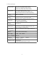
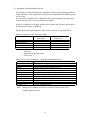
1.1.2 Basic Specifications
Printing method
Image Area: Dye Diffusion Thermal Transfer
Character Area: Molten Type Thermal Transfer
Protective Layer: Molten Type Thermal Transfer
Printing Media
PVC Card (Recommended Card by NISCA)
Size:Conform to JIS X 6301 (ISO standard CR-80 )
Thickness:Conform t o J I S X 6 3 0 1(ISO standard CR-80 )
Printing
Resolution
300dpi (11.81dots/mm )
Printing
Grayscale
Input:256 grayscale for each colors R,G and B
Output:256 grayscale control for each colors C,M and Y
Printing Size
Max. 85.5mm (card longitudinal )
(
54mm~ card transverse
direction
)
Printing
Arrangement Area
Max. Entire area
Printing Speed
45seconds per card excluding communication time at the
whole area printed as mentioned above.
Supply method
and capacity
100 cards(card thickness:0.76mm );supplied automatically
Interface
SCSI or Parallel (Fixed in factory )
Power supply
AC 100 ` 240V 50/60Hz
Power consumption 120W max.
Equipment
dimensions
421mm(H ) 271mm~ W
(excluding Stack Box )
Equipment weight
13kg:Main body
13.8kg:Including optionalmagnetic encoder
1-2
( ) D
331mm
~
( )
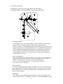
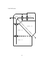
1.2 Mechanical Operation
Thisequipment consists of Card Supply Block, Flip Turn Block,
Card Ejection Block, Card Encoding Block and Card Rejection Block.
F
@ Card Supply Block
Card Supply Box can contain up to 100 pcs of standard plastic cards (0.76mm
thick) so that a continuous printing of high volume card is possible.
The box is made of a transparent plastic for easy checking of the remaining card
supply and protecting the cards from dust.The card is fed fromthebottom of the
pile and automatically transported in the printer. A weight plate is provided to
ensure the positive feeding of cards when the remaining cards becomes low.
Card separation is done by the gateattheentrance,whichcan be adjusted to
various thickness of cards.
A Card Cleaning Block
There are two rubberrollers with sticky surface to removedust.One is for frontside of a
card and the other is for back side of the card.Since this printer has this feature it is
possible to makeprinting process faster and clear atdualsideprinting.
It isnecesary to clean thempiriodically to let themkeepthis performance.
See section4 forhowto clean them.
B Flip Turn Block
To turns the card for both side printing. This block also serves to switch the card
path to Print Block, Eject Block and Reject Block. Itispossible to rotate the this
block manually. Never touch the part besides green color part when you need to
rotate this blok manually.
C Print Block
The card moves back and forth in the Print Block 5 times to be printed with 3
colors, black and overlay. Print Block consists of Card TransportModule, Print
1-3
Head ModuleandRibbonFeedModule.
In the Card TransportModule, the card is transported by two pairs ofcapstan rollers
placed in front and behind platen roller. While printing,the nip release mechanism
works to eliminate the shock of the card entering the printing block and provide a
smooth and clear printing.
Each roller is precisely driven by stepping motor to minimize the color deviation
and the side of the card is controlled to limit skew.
A high resolution (300 dpi ) thermal head is used in the Print Head Module for
clear and high quality image printing. An even pressure (Approx.2.0 Kg ) is given
to the thermal print head by two coil spring located at both end of the head to
maintain uniform contact to the card. The thermal head is assembled in one
independent unit so thatthereplacementismadevery easy.
Also a user can replace the print head and ribbon at front side by featuring front
access system.
Ribbon Feed Module has Feed Bobbin, Transport Roller, Take-up Bobbin and
driven by each independenttorque limitter so that the ribbon can be fed with
constant tension for stable printing. Take up bobbin is driven at two speeds, slow
for printing and high for non-printing, which makes the efficient operation possible.
D Card Encode Block
Magnetic Encode Unit, IC Encode Unit, etcareavailable for this printer as optional
unit. By mounting the Encode Unit, printing of image and characters, encoding
magnetic( or I C ) data can be processed in one operation in one equipment. As the
Encode Unit can be mounted in the Printer,it does not require additional desk space.
E Card Reject Block
If a trouble occurs while printing, the printer stops automatically.In such case, by
pressing "Clear" key, the card currently being printed will be ejected through Reject
Exit.
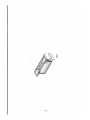
F Card Ejection Block
Card Ejection Block has a transparentcardstackbox.Theprinted cards are ejected
in this box and stacked ( 100 cards of standard thickness ).
The box has a cut out for easy removal of the printed cards.
1-4
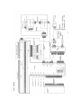
1.3
Electrical operation
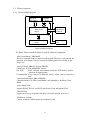
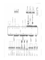
1.3.1. Electrical Block Diagram
Operation
Panel Board
Thermal
Head
Main Circuit
Board
Mechanical
Actuators
Interface
Board
Power Supply
Unit
Printer Unit Block Diagram
The Printer Unitiscontrolled and driven with the following components.
(
)
Main Circuit Board PBA-MAIN
Receives commandsanddatafromthehostthroughSCSIinterfaceandcontrols the
operation of the Printer Unit,also controls the thermal print head according to the
image data.
( PBA-IFP
)
Interface Board PBA-I/F- SCSI or
Controls the SCSI or PARALLEL interface.
For SCSI
:It has connector and terminator switch for SCSI interface and has
connector for optional units.
For PARALLEL : It has aconnector for IEEE1284 interface and has connector foroptional
units
(
)
Operation Panel Board PBA-OPEPANE
Constituted with LCD, LEDs, Push Buttons, and controlled by the Main Circuit
Board.
Power Supply Unit
Supplies DC24V, DC16V and DC5VtothePrinterUnit and Optional Unit.
Thermal Head
Supplies head energy for printing the image, characters and OP (over coat ).
Mechanical Actuators
Consists of sensors and the motors to transportthecards.
1-5
1.3.2 Main Circuit Board (PBA-MAIN )
There are CPU Block, Memory Block, Actuator Control Block.
<CPU Block >
CPU Block has the following functions:
o Controltheinterface with the host computer.
o Transmit data and commands to Image Memory Block, Image Correction Block,
and Thermal Head Control Block.
o Controls the Mechanical Actuators..
o Transmit data and commands to the Optional Units. (Serial communication )
o Controltheuser interface with the Operation Panel Board.
Following items are the main components:
(
)
32 bit CPU IC1
32 bit single chip micro processor, activated on the clock of 12.5 MHz (OCS1 )
( )
Flash Memory IC5
A memory of 2 M bytes forstoring the firmware of CPU(IC1 ) and data for thermal
head.
Itcan be downloaded through the SCSI interface.
)
SRAM IC3,4 (
256K byte memory to be used by CPU(IC1 ) to store the data.
Serial EEPROM IC8
(
)
2K byte memory to record totalframe number, number of errors, setting values of
the specific unit, etc.
(
)
Serial interface driver IC33
Translated the signal of CPU to RS232C forcommunication with the built-in encoder
unit.
(
)
DRAM IC11
Memory of 8 M byte which stores the data of RGB +characters for 2 frames.
Control IC IC12
(
)
A Gatearray to control theprinteractivated ontheclockof20MHz.
This IC controls following items by setting from CPU
> To controlthetransfer of the image data to DRAM (IC16, IC17 ) and also image
rotating function.
> To control the thermal head
> Interface for SCSI or PARALLEL control IC
> To control the LCD
> Reset control: Watch dog timer
> To supply driving signals for PM 1-3
> To generate the control signal for DM1
> To control sensors
> To control the version of circuit boards and gate array
1-6
<Mechanical Actuator Control Block >
Actuates sensors and motors which are controled by CPU (IC1 ).
) circuit
Sensor SN15 (adjustment
Transform the analog output voltage of the CPU (IC1 ) into energizing current of the
LED. It consists of comparator (IC29 ) which converts the output signal of the photo
transistor proportional to the energizing current.
SensorInput Circuit
This is a circuit consisting of an integrating circuit with resistors and capacitors, and
inverters (IC 21, 22, 26, 27 ).
DM1 Driving Circuit
Transistor (Q10,17,18,19 ) drives the DM1 and breaking circuitisactivated when
DM1 stops.
PM1 Driving Circuit
Unipolar, constant current chopper type driver (IC24 ) drives.
Driving signalissupplied by control IC (IC2 ).
PM2 Driving Circuit
Unipolar, constant current chopper type driver (IC17 ) drives.
Driving signalissupplied by control IC (IC2 ).
PM3 Driving Circuit
Unipolar, constant current chopper type driver (IC18 ) drives.
Driving signalissupplied by control IC (IC2 ).
HFANDriving Circuit
HFAN is driven by transistor array (IC30 ).
Fan motors have built-in abnormality detector circuit, which controls the driving
current and transmit alarm signal when abnormal rotation is detected.
DFANDriving Circuit
DFAN is driven directly by the current supplied from Power Supply Unit.
1-7
1.3.3 Interface Board (PBA-I/F )
Interface board applies to SCSI-2 or IEEE1284 standard.
<SCSI type interface board >
There a r e t w o "half 50" pin connectors on the interface board. Also, there is a
connector for connecting the optional device.
(
)
Serial interface driver IC36
Translates the signal of CPU to RS422 levelforthecommunication with the attached
optional equipment.
( )
SCSI Controller IC2
Operates on the clock frequency (OSC1 ) of 20MHz and controls SCSI bus.
SCSI terminator IC3
( )
An active terminator IC supporting the SCSI specification which terminates the SCSI
bus by the input of the switch (SW2 ) located on the backside of the printer.
<PARALLEL type interface board >
There is "half 36" pin connectors on the interface board. Also, there is a connector for
connecting the optional device.
(
)
Serial interface driver IC36
Translates the signal of CPU to RS422 levelforthecommunication with the attached
optional equipment.
( )
IEEE1284 controller IC1
Controlls the interface between IEEE12824 bus and Control IC (IC2 ) located on
main board and activated with 20 MHz clock (generated by OSC1 )
PROM for Control IC
To store the program data for controlIC.
This device is fit into a socket.
IEEE1284 Driver IC
To drive and receive the signals with peripheral equipment.
Applied to IEEE standard
1-8
1.3.4 Operation Panel Board ( PBA-OPEPANE )
Operation Panel is used to indicate the current situation of the Printer to the operator, to
change setting,execute printing,and clearing errors.
)
LCD IC1 (
LCD panel of 16 characters * 2 lines. Displays the condition of the printer, setting and
changes of values, error messages, etc.
LED1 - LED3
Indicate the Printer condition to operator.
SW1 - SW3
Switches for operator to operate the Printer.
Note: Details of operating the Operation Panelisexplained in Section 3,
Operation Panel.
1-9
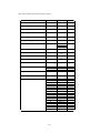
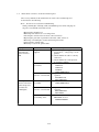
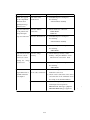
1.3.5 Mechanical Actuators
The PrinterMechanism consists of Sensors and Motors, etc.
<Input mechanisms >
Symbol
SN1
SN13
Component
Optical Sensor
(Single unit )
Optical Sensor
(Single unit )
Optical Sensor
(Single unit )
Optical Sensor
(Single unit )
Optical Sensor
(Single unit )
Optical Sensor
(Single unit )
Optical Sensor
(Single unit )
Optical Sensor
(Single unit )
Optical Sensor
(Single unit )
Optical Sensor
(Single unit )
Optical Sensor
(Single unit )
Microswitch
SN14
Microswitch
SN15
Optical Sensor
(Single unit )
SN2
SN3
SN4
SN5
SN6
SN7
SN8
SN10
SN11
SN12
Function
Detection of card empty at Card Supply
Block.
Detection of card position
(Just before Cleaning Roller ).
Detection of card position
(Just before Flip Turn Unit ).
Detection of card position
(Just before Print Block ).
Detection of card position
(to detect the leading edge of a card ).
Detection of the home position of Flip Turn unit.
Detection of the angleofFlip Turn unit.
Detection of lengthofribbonfed.
Detection of mark on the ribbon.
Detection of printhead position.
Detection of printhead position.
Detection of open/closeofFrontCover.
(with interlock function )
Detection of open/closeofTopCover.
(with interlock function )
Detection of card position
(just before encoder )only available when Encoder set.
<Output Mechanisms >
Symbol
DM1
Component
DCMotor
PM1
Pulse Motor
PM2
PM3
HFAN
DFAN
Pulse Motor
Pulse Motor
Fan Motor
Fan Motor
Function
Rolls up Ink Ribbon.
Moves (up/down ) Thermal Head
Drives rotation mechanism in Flip Turn Block.
Transports a card ( Card Supply Block )
Transports a card (Flip Turn Block )
Transports a card (Print Block )
Cools Thermal Head.
Cools PowerSupply.
1-10
Section 2 Setting Up
2. 1 Setting Up
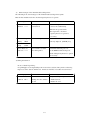
2.1.1 Caution forsetting up
Dusty place must beavoided for using this equipment because the printing system of this
printer is especially sensitive to dust. When printing on thecardwithmagneticstripe,
do not place the printer at near the equipment which is emitting magnetic field. Other
than above, use general caution for setting up other OAequipments and choose proper
place with proper environment. For further details, please read operation manual.
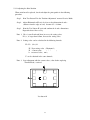
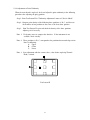
2.1.2 Space for installation
The space for the operation as
shown in the illustration should
be provided.
At least 50 cm 20 inch of
clearance should be kept for
the Top Cover.
Table to place the printer
should be able to hold
minimum 14Kg 31lbsi and
have flat top and 4 rigid legs.
It should notincline more
than 1 K.
15cm
6inch
i
j
15cm
6inch
15cm
6inch
j
30cm
12inch
2-1
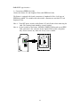
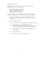
2.1.3 Connection to Host Computer with SCSI or PARALLEL
<SCSI type interface >
1) Connection of SCSI Cable
Connect the Printer, PC and Peripheral Units with SCSI Cable.
The Printer is equipped with two female connectors of 50 Pins (half type )of SCSI
specification. Use suitable SCSI cable with suitable connectors to match the PCand
Peripheral Units.
OPTION
SCSI-2
SCSI-1
TRM
Note 1: Total length of the SCSI cable should be within 6 meters.
To ensure stable operation, within 4 metres is recommended.
Note 2: Please use the SCSI - IIspecification high impedance cable. In case of daisy
chain connection, operation may become unstable unless all cables are SCSI-II
specification.
Note 3: Turn OFF power switches of the Printer, PCand all units when connecting the
cable. The retaining hook should be securely latched.
Note 4: On the backside of the Printer, OPTION CONNECTOR located next to SCSI
connectors is the connectorfortheOptional Units of this card printer only.
Do not connect any other unit. It may cause a trouble.
Interface connectors
2-2
2 ) Setting internal SCSI Terminator.
The Printer has Active Terminator for SCSI-I and SCSI-II.
When using the Terminator, turn the switch at the back of the Printer ON (upper side ).
(Turn OFF the power switch when operating this. )
To switch on
TRM
ON
To switch off
Appearance of Terminator switch
3 ) Setting SCSI ID Number
The SCSI ID number can be freely selected from 0 to 7 through the operation panel of
the printer.
Default ID setting is 4.
Note 1: Do not set the same ID number as the PC and other peripheral units. ( It may
cause a trouble.)
When setting, check the ID numbers of the other units.
Note 2: When setting the ID number, turn OFF the power switches of PC and all other
peripherals.
2-3
<PARALLEL type interface >
1) Connection ofIEEE1284 Cable
Connect the Printer, PC and Peripheral Units with IEEE1284 Cable.
The Printer is equipped with female connectors of Amphenol 36 Pins (half type )of
IEEE1284 standard. Use suitablecablewithsuitable connectors to match the PC and
Peripheral Units.
Note 3: Turn OFF power switches of the Printer, PCand all units when connecting the
cable. The retaining hook should be securely latched.
Note 4: On the backside of the Printer, OPTION CONNECTOR located next to IEEE
1284 connectors is the connector for the Optional Units of this card printer
only. Do not connect any other unit. It may cause a trouble.
2-4
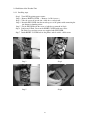
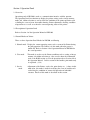
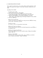
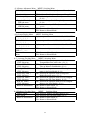
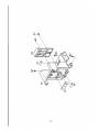
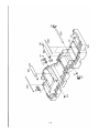
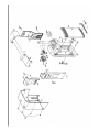
2.2 Instllation of the Encoder Unit
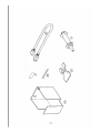
2.2.1 Installing steps
Step 1
Step 2
Step 3
Step 4
Turn OFF the printer power source.
Remove RIGHT-COVER. ( Remove 2 x M-4 screws )
Take the screw off to take out a slide for a card rejected .
InserttheENCODER into theencoderspace of the printer with connecting the
two harnesses fromtheprinter.
Step 5 Fix the ENCODR with the screw of which was removed in Step3.
Step 6 Putthesmall Exsit Cover on the RIGHT-COVER with two screws.
The Exit Cover and two screws are supplied with ENCODER.
Step 7 PuttheRIGHT-COVER back to the printer and fix with 2 x M-4 screws
Step 3
Step 4
Step 5
Step 6
2-5
Section 3 Operation Panel
3.1 Overview
Operation panel of PR5300 is used as a communication interface with the operator.
The Operation Panel has functions to display the printer setting such as image memory
mode, ink ribbon selection etc and to check the condition of the printer operation such
as finding the cause of error for trouble shooting, Printer adjustment, checking condition
of operation etc as well as to show the current operating status of the printer.
3.2 Description of Operation Panel
Refer to Section 4 of the Operation Manual of PR5300.
3.3 InternalModesof Printer
There are three Operation Panel Modes for PR5300 as following
1. Normal mode Display the current operating status, such as error,of the Printer during
the print operation. The Printer is in this mode when the power is
turned ON. Refer to Section 4-b of Operation Manual of PR5100 for
the actual operation.
2. User mode
This mode is used to set the Printer conditions such as setting of image
memory, ink ribbon selection etc. Also, used to show the information
such as the ROM version etc. For the operation refer to Section 4-b of
the Operation Manual. In this section of this booklet, print mode only
is explained. (3.3.4 )
3. Service
mode
Adjustment of the Printer, such as the print density etc, is done in this
mode Also, this mode is used for analyzing the cause of troublessuch
aschecking the condition of sensors and operation of individual
actuators. Details of this mode is described in this section.
3-1
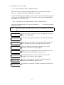
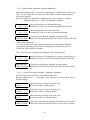
3.3.1 OPERATIONOFSERVICE MODE
Service mode is the mode for the service person to adjust and check performance of the
printer. The image data in the printer is cleared when switched to and from the service
mode.
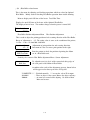
Switching to Service Mode
1.
2.
3.
4.
To switch to service mode,
Return fromtheothermode to NormalMode.
In the idle or error mode, keep the MENU key pressed till it becomes
Command Reception Mode. ("Input Command" appears on the LCD panel )
While pressing the MENU key, press EXE and CLEAR keys alternately
(about 8 times ) till the display changes from "Input Command" to "Service Mode".
Release the MENU key.
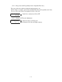
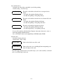
Moving in the Same Directory
To move in the directory, press MENU key to change the menu. MENUwill change
in the set order when the key is pressed.
Execution of a menu
See section 3.3.2 and 3.3.3 for operation of current menu.
Moving to the Lower Layer Directory
To enter into the directory of the lower layer from the present layer, press EXEkey at
the appropriate menu.
Returning to the Upper Layer Directory
To go one layer higher than the present, switch the menu to "Return to ParentMenu"
and press EXE key.
Returning to Normal Mode
Switch the menu to "Return to Normal Mode" and press EXE key or switch the
menu to "Return to Parent Menu" and press CLEAR key.
3-2
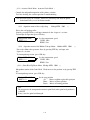
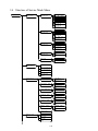
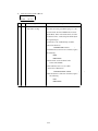
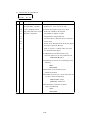
3.3.2 Menu Structure of Service Mode
The Menus of Service Mode are as follows. The part in rectangle will be displayed only
when the referred optional units are connected.
(S ) Main Menu
(S-1 )Printer AdjustmentMenu
(S-1-1 )Max Density Adjustment Menu
(S-1-2 )Print Position Adjustment Menu
(S-1-3 )3 point Correction Adjustment Menu
(S-1-4 )Image Cut off length Adjustment Menu
(S-1-5 )Density of LCD panel Adjustment Menu
(S-2 )Sensor Display Menu
(S-3 )Actuator Operation
Checking Menu
(S-3-1 )Card Pick Up Motion Menu
(S-3-2 )Ribbon Feed Motion Menu
(S-3-3 )Head Up/Down Motion Menu
(S-3-4 )Flip-Turn Motion Menu
(S-3-5 )Flip-Turn,Card Transportation Menu
(S-3-6 )Print Block Card Transportation Menu
(S-4 )Hardware Checking Menu
(S-5 )Card Eject Setting menu
(S-6 )UserModeItems Setting menu
(S-7 )Heat Roller Related Menu
(S-8 )Encoder Related Menu
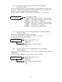
(S )Main menu
'Adjustment Mode'
'Sensor Check'
'Actuator Check'
'Hardware Check'
'Eject Position'
'User Menu Config.Mode'
'Encoder Check Mode
'Heat Roller Check
'Return to NormalMode'
MENU: Switching menu
EXE: Switch to Printer AdjustmentMenu(S-1 )
EXE: Switch to Sensor Display Menu(S-2 )
EXE: Switch to Driving Motion Checking Menu(S-3 )
EXE: Switch to Memory Checking Menu (S-4 )
EXE: Switch to Card Eject Setting menu (S-5 )
EXE: Switch to UserModeItems Setting menu (S-6 ).
EXE: Switch to Encoder Related Menu (S-7 )
EXE: Switch to Heat Roller Related Menu (S-8 )
EXE: Returns to NormalMode
CLR: Returns to NormalMode
3-3
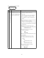
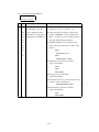
(S-1 )Printer Adjustment Menu MENU: Switching Menu
'OD Adjustment'
EXE:Switch to Max Density Adjustment Menu(S-1-1 )
'Position Adjustment'
'Uniformity Adjustment'
'Expanded Dt Adj
EXE:sub menu
LCD Adjustment
EXE:sub menu
'Return to ParentMenu'
(S-2 )Sensor Display Menu
SN 01 02 03 04 05
* * * * *
SN 06 07 08 10
* * * *
SN 11 12 13 14 15
* * * * *
Auto Adjustment
EXE:----- ----Return to Parent
Menu
EXE:Switch to Print Position Adjustment Menu (S-1-2 )
EXE:Switch to 3 points Correction AdjustmentMenu
(S-1-3 )
EXE:Switch to Image Cut Off Length Adjustment Menu
(S-1-4 )
EXE:Switch to density of LCD adjustment Menu
(S-1-5 )
EXE: Returns to Main Menu (S )
CLR: Returns to NormalMode
MENU: Switching Menu
Display output of Sensor 01,02,03,04,05,(1:ON,2:OFF )
Display output of Sensor 06,07,08,10(1:ON,2:OFF )
Display output of Sensor 11,12,13,14,15(1:ON,2:OFF )
EXE: Automatic Adjustment of Sensor 11
EXE: Returns to Main Menu(S )
CLR: Returns to NormalMode
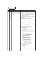
(S-3 ) Actuator Checking Menu
MENU: Switching Menu
'Pickup MTR. (DM1 )'
EXE: Switch to the operation menu of the Card
EXE: Sub menu
TransportMotorinCardFeeder (S-3-1 )
'Ribbon MTR.(DM2 )'
EXE: Switch to the operation menu of the Ribbon
EXE: Sub menu
Take up Motor in PrintModule(S-3-2 )
'Headup MTR.(DM3 )'
EXE: Switch to the operation menu of Head up/down
EXE: Sub menu
motor in the Print Module(S-3-3 )
'F.Turn Ang.(PM1 )'
EXE: Switch to the operation menu of Flip Turn
EXE: Sub menu
Module Rotation motor.(S-3-4 )
'F.Turn Trf.(PM2 )'
EXE: Switch to the operation menu of Card Transport
EXE: Sub menu
Motor in the Flip Turn Module (S-3-5 )
'Print Trf. (PM3 )'
EXE: Switch to the operation menu of Card Transport
EXE: Sub menu
Motor in the Print Module.(S-3-6 )
'Return to ParentMenu'
EXE: Returns to Main Menu (S )
CLR: Returns to NormalMode
(S-4 )Hardware Checking Menu
MENU: Switching Menu
'Address Check'
EXE: Switch to Address Checking Menu(S-4-1 )
'Data Check'
EXE: Switch to Data Checking Menu(S-4-2 )
'Return to ParentMenu'
EXE: Returns to Main Menu(S )
CLR: Returns to NormalMode
3-4
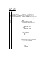
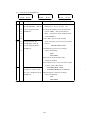
(S-5 ) Card Ejection Setting Menu
MENU: Switching the meue
'Stuck Position'
EXE: Designates the place of ejection of the
***********
normally finished card.
'Reject Position'
EXE: Designates the place of ejection of the card
***********
finished in error
'Select Action'
EXE: Designates the action pattern of card transportation
***********
'Print Number '
Designates the Number of card transportation action
***********
EXE: Increment of value CLR:Decrement of value
'Card Pass Test'
EXE: Executes the card transportation.
EXE: Start
'Return to ParentMenu'
EXE: Returns to the Main menu (S ).
CLR: Returns to the Normal mode.
(S-6 ) User Mode Items Setting Menu
MENU: Switching the menu
Ribbon Menu Disp
EXE: Permit/Prohibit of "Ribbon Type" in the User
(on/off )
Mode.
AdjustMenuDisp
EXE: Permit/Prohibit of "Color Adjustment" in the
UserMode.
(on/off )
Status Menu Disp
EXE: Permit/Prohibit of "Printer Status" in the Use
Mode.
(on/off )
Return to Parent Menu
EXE: Returns to the Main Menu (S ).
CLR: Returns to the Normal Mode.
(S-7 )Encoder Related Menu
'********** Test'
(**** ) EXE:Start
'Return to Parent'
Menu
Menu: Switching Menu
EXE: Writes encode data on the displayed track.
EXE: Returns to Main Menu(S )
CLR: Returns to NormalMode
(S-8 )Heat Roller Related Menu
MENU: Switching Menu
'Heat Total Time'
Displays the total on time of the heater
*****
' Position Adj. '
EXE: Increment of value
***
CLR: Decrement of value
'Heat Roller Test'
EXE: Printing Test Pattern
EXE:Print
CLR: Clearing Errors
' Sensor Adj '
EXE:Adjustthesensivity for ribbon position sensor in
EXE:Start
Heat Roller
'Return to Parent'
EXE: Returns to Main Menu(S )
Menu
CLR: Returns to NormalMode
3-5
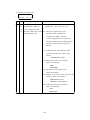
(S-1-1 )Max Density Adjustment Menu MENU: Switching Menu
'ODAdj.Color'
EXE: Increment of value
CLR: Decrement of value
'Zero Adj. Color
EXE: Increment of value
CLR: Decrement of value
'ODAdj.Black'
EXE: Increment of value
CLR: Decrement of value
'Zero Adj. Black
EXE: Increment of value
CLR: Decrement of value
'ODAdj.Clear'
EXE: Increment of value
CLR: Decrement of value
'Zero Adj. Clear
EXE: Increment of value
CLR: Decrement of value
'Color Adjustment'
EXE: Print Test Pattern J
Test Print
CLR: To Release the error
'Black Adjustment'
EXE: Print Test Pattern E
Test Print
CLR: To Release the error
'Return to ParentMenu'
EXE: Returns to Printer Adjustment Menu(S-1 )
CLR: Returns to NormalMode
(S-1-2 )Print Position Adjustment Menu
MENU: Switching Menu
' Horizontal Adj.'
EXE: Increment of value
CLR: Decrement of value
' Vertical Adj.'
EXE: Increment of value
CLR: Decrement of value
'Black Shift Adj.'
EXE: Increment of value
CLR: Decrement of value
'Position Adj
EXE: To Print Test Pattern H
EXE:Test Print'
CLR: To Release the error
'Black Shift Adj.'
EXE: To Print Test Pattern M
EXE:Test Print'
CLR: To Release the error
'Return to ParentMenu'
EXE: Returns to Printer Adjustment Menu(S-1 )
CLR: Returns to NormalMode
(S-1-3 )3 Point Correction Adjustment Menu MENU: Switching Menu
'Uniformity Adj.'
EXE: Increment of value
Lower
CLR: Decrement of value
'Uniformity Adj.'
EXE: Increment of value
Center
CLR: Decrement of value
'Uniformity Adj.'
EXE: Increment of value
Upper
CLR: Decrement of value
'Color Uniformity'
EXE: Print Test Pattern H
Test Print
CLR: To Release the error
'Black Uniformity'
EXE: Print Test Pattern E
Test Print
CLR: To Release the error
'Return to ParentMenu'
EXE: Returns to Printer Adjustment Menu(S-1 )
CLR: Returns to NormalMode
3-6
(S-1-4 ) Image Cut Off Length Adjustment
MENU:Switching Menu
'Data Cut Enable
EXE: Settheimagecuttingoff function enable or
disable for the image which out of printing area.
(On/Off )
'Return to ParentMenu'
EXE: Returns to Printer Adjustment Menu(S-1 )
CLR: Returns to NormalMode
(S-1-5 ) Density of LCDAdjustment Menu
MENU:Switching Menu
LCD Adjustment
EXE: Inclement of value
CLR: Declement of value
****
'Return to ParentMenu'
EXE: Returns to Printer Adjustment Menu(S-1 )
CLR: Returns to NormalMode
3-7
(S-3-1 ) Operation Menu of the Card Transport Motor in the Card Feeder
MENU: Switching the menu
Pickup MTR (PM1 ) EXE: To pick up a card
EXE: Start
Return to Parent Menu
EXE: Returns to Actuator Checking Menu
CLR: Returns to NormalMode
(S-3-2 ) Operation Menu of the Ribbon Take Up Motor in the PrintModule
MENU: Switching the menu
Ribbon MTR (DM1 )
EXE: Takes up the ribbon.
EXE: Roll Up
Return to Parent Menu EXE: Returns to Actuator Checking Menu
CLR: Returns to NormalMode
(S-3-3 ) Head Up/Down Motion Menu MENU: Switching Menu
Head up MTR (DM1 )
EXE: To moves the head to next position.
EXE: ******
'Return to ParentMenu
EXE: Returns to Actuator checking Menu (S-3 )
CLR: Returns to NormalMode
(S-3-4 ) Operation menu of the Flip Turn unit Rotation Motor
MENU: Switching the menu
F.Turn Ang. (PM1 )
EXE: To rotate the F.Turn module to next angle position
EXE: ******
Return to ParentMenu
EXE: Returns to Actuator Checking Menu (S-3 )
CLR: Returns to the Normal Mode.
(S-3-5 ) Operation menu of the Card TransportMotorintheFlipTurnModule
MENU: Switching the menu
F. Turn Trf. (PM2 )
EXE: To transport the card in Flip Turn Module.
EXE: Start
Return to Parent Menu
EXE: Returns to Actuator Checking Menu (S-3 )
CLR: Returns to the Normal Mode.
(S-3-6 ) Operation menu of the Card TransportMotorinthePrintModule
MENU:
Switching the menu
Print MTR
EXE: To transport the card in Print Block.
EXE: Start
Print Trf. REV
EXE: Transports in the reverse direction.
EXE: Start
Raturn to Parent Menu
EXE Returns to Actuator Checking Menu (S-3 )
CLR: Returns to the Normal Mode.
3-8
3.3.3 Description of Service Mode
¡(S-1 ) Printer Adjustment Menu (Adjustment Mode )
This is the menu to adjust the printing conditions such as print position and print
density etc. Mainly used when the Print Head is replaced.
If the error LED lights when printing test pattern, clear the error by removing the cause
and pressing the CLEAR key. Iftheerror can not be cleared, return to NormalMode
and confirm the nature of the error.
(S-1-1 ) Adjustment of the Maximum Density Menu (
ODAdjustment )
Adjust the maximum density. The range of adjustment i s - 7 `+7 for color, resin black
and protective layer.
Note:
Do not increase the value unnecessarily. Itmaycause ribbon peel off (blotch )
error.
OD Adj. Color
-7 -- +7
Adjust the energy to print color image. The higher the value, the
deeper the color becomes.
Zero Adj. Color
In the color image printing, adjusts the energy for the preheating.
OD Adj. Black
Adjust the energy to print the heatmelting black. The higher the
value, the higher the energy to print the heattransfer black.
Zero Adj. Black
In the heat transfer black printing, adjust the energy for the
preheating. This affects the edge sharpness.
OD Adj. Clear
Adjust the energy to print protective layer. The higher the value,
the higher the energy to print the protective layer.
Zero Adj. Clear
In the printing of protective layer, adjust the energy for the
preheating. This affects the edge sharpness.
Color Adjustment
EXE:Test Print
To print the test pattern for checking the maximum density of
color print and condition of protective layer.
Black Adjustment
To print the test pattern for checking the condition of black print.
EXE:Test Print
3-9
(S-1-2 ) Print Position Adjustment (
Position Adjustment )
Adjust the printing position. The range of adjustmentis+/-50forholizontaldirection
and +/- 16 for vertical direction. The value is the number of dots for both horizontal
and vertical direction.
Since the resolution of this printer is 300 dots per inch, the formula is as follows:
Adjustment value of 1 = 1 dot = 25.4mm/300 = 0.085mm.
Horizontal Adj.
-50 ---- +50
Vertical Adj.
-16 ---- +16
Position Adj.
EXE: Test Print
Adjust the position in the holizontal direction.
Increment in value is to move the print position to the right.
Adjust the position in the vertical direction.
Increment in value is to move the position downward.
To print the test pattern for adjusting the print position.
Adjust the value for positionig the color image in center of the card.
<Black Shift Adjustment >
To correct the divergence of the print position between color printing and black
printing when print the pattern of which beginning point of print i s n o t s a m e o f
the data for color and black each other.
Note : The divergence of print position depends on the printing pattern
Black shift Adj.
-10 ---- +10
Black Shift Adj.
EXE: Test Print
Adjust the distance of transporting the card not in printing process .
Increment in value is to move the beginning point of print of the
To print the test pattern for adjusting the print position.
Adjust the value for the black line is positioned in center of white
line.
(S-1-3 ) 3 points Correction Adjustment (uniformity Adjustment )
Correct the unevenness of density in the holizontal direction.
Range of adjustment is -9 ` 0 for upper, center and lower area. Increment in value is
to higher density.
Uniformity Adj.
Upper
Adjust the energy for upper area of the card.
Increment in value is higher density.
Uniformity Adj.
Center
Adjust the energy for center area of the card.
Increment in value is for higher density.
Uniformity Adj.
Lower
Adjust the energy for lower area of the card.
Increment in value is for higher density.
Black Shift Adj.
EXE: Test Print
To print the test pattern for adjusting the uniformity of the density.
Adjust the value for the density ofall3areasaresameeachother.
3-10
(S-1-4 ) Image datacutofflengthAdjustment. (
Expanded Data Adj. )
This cuts off the data which overflowed fromtheprinting area.
If this setting is accepted, a part of the transmitted data may not be printed.(max 1mm )
The area of the data which is not printed varies by each card.
Data Cut Enable
ON/OFF
SettheData cutfunction ON or OFF
(S-1-5 ) Density of LCD panel Adjustment.
LCDAdjustment
-3 ---- +3
Adjust the density of LCD panel
Increment of the value for higher dencsity.
3-11
¡(S-2 ) Sensor check Menu (Sensor Check Mode )
This is the menu to display the sensor outputs and automatic sensor adjustment. Used to
check the condition of the printer when troubleshooting.
SN 01 02 03 04 05
* * * * *
SN 06 07 08 10
* * * *
SN 11 12 13 14 15
* * * * *
Displays the sensor output. The display is made according as the logic table of the
sensors. The correspondence of the sensors is as following. The names correspond to
the names used in the Electric Parts Layout.
SN1
SN2
SN3
SN4
SN5
SN6
SN7
SN8
SN10
SN11
SN12
SN13
SN14
SN15
Detection
Detection
Detection
Detection
Detection
Detection
Detection
Detection
Detection
Detection
Detection
Detection
Detection
Detection
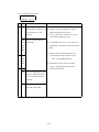
Auto Adjustment
***
***
of card empty atCardSupplyBlock
of card position (Justbefore Cleaning Roller ).
of card position (Justbefore Flip Turn Unit ).
of card position (Justbefore Print Block ).
of card position (to detect the leading edge of a card ).
of thehome position of Flip Turn unit.
of theangleofFlipTurn unit.
of length of ribbon fed.
of mark on the ribbon.
of print head position.
of print head position.
of open/close of Front Cover.(with interlock function )
of open/close of Top Cover.(with interlock function )
of card position(just before encoderonly available when Encoder set )
Shows difference between expected and actual output
voltage. 1 = 0.02V.
Shows input voltage of the LED
The sensor 10 is automatically adjusted and the condition of the light emittanceand
reception of the sensor is checked. In the display of the details menu of each sensor, the
input voltage of the light emitting elementisshownonthelowerleftsideandthe
difference between the actual output voltage and the expected voltage of the receiving
element on the lower right side.
Note: When adjusting the automatic adjustment, remove the object at the sensor.
Otherwise, the automatic adjustment will not be made normally.
3-12
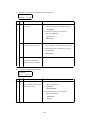
¡(S-3 ) Actuator Check Menu (
Actuator Check Mode )
Controls the independent operation of the printer actuators.
Used for checking the actuator operation in troubleshooting.
note:Whenchecking the actuators, remove the remaining card from the printer
beforehand. Itmaycause the Printer trouble.
(
)Operation menu of thecardpickup
S-3-1
(
(
Pickup
MTR. PM1
))
Drives the card pick up roller.
Starts by pressing EXE key and stops automatical after elapse of a set time.
To interrupt the operation, press CLR key.
Pickup MTR.(PM1 )
EXE:*****
Set the transpotation speed
LDRV: Slow
HDRV: Fast
(
)Operation menu of the Ribbon Take-up Motor
S-3-2
(
(
Ribbon
MTR. DM1
))
Drives the ribbon take-up motor. Starts by pressing EXE key and stops after
elapse of a set time.
To interrupttheoperation, press CLR key.
Ribbon MTR.(DM1 )
EXE:*****
Set the transpotation speed
LDRV: Slow
HDRV: Fast
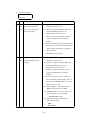
(S-3-3 ) Print Head Up/Down Menu (
(
))
Headup MTR. DM1
Independent motion of the Print Head. Head moves to the position set by presing EXE
key.
To interrupttheoperation, press CLR key.
Headup MTR.(DM1 )
EXE:*****
Set the stop position
UP : Moves to ribbon replaceable posiyion
Home : Moves to Home position
Down : Moves to Printing position
Note
Do not operates the transportation motor in print block when print head position is
at DOWN
It may cause the print head damaged.
3-13
S-3-4
(
)Operation menu of the rotation motor of the Flip Turn Module
(F.Turn Ang. (PM1 ))
Drives the rotation motor of the flip turn module by pressing EXE key and stops at the
position set . TherearetwopositionstoEachstoppingposition. One is normal and
the other is reverse position as180degreeagainstnormal.
Display shows these positions as "F(forward )" and "R (Reverse ) foreachmenu.
F. Turn Ang. (PM1 )
EXE:***
Setthestopping position
F_ENCODE :The position at passing a card to Encoder
F_PRINT :The position at passing a card to print block
F_HOME
:The position at a card supplied
F_ENCODE :The position at passing a card to Encoder
F_PRINT :The position at passing a card to print block
F_HOME
:The position at a card supplied
ETERNITY :Keeps rotating till CLR key pressed
S-3-5
(
) Operation menu of the Card Transport Motor in the Flip Turn Module
( F. Turn Trf. (PM2 ))
Drives the card transport motor in Flip Turn Module
Starts by pressing the EXE key and stops after elapse of a set time.
To interrupttheoperation, press CLR key.
F. Turn Trf. (PM2 )
EXE:*** ***
Set thecardtrnspotation speed
LDRV: Slow
HDRV:Fast
Set the directin of card transportion
CCW
CW
S-3-6
(
)Operation menu of the Card Transport Motor in the Print Module
(Print Trf. (PM3 ))
Transports the card in the print module . There are 3 menus, normal, reverse and print
transportation.
Starts by pressing the EXE key and stops after elapse of a set time.
PrintMTR. (PM3 )
EXE:*** ***
Set thecardtrnspotation speed
LDRV: Slow
HDRV:Fast
Set the directin of card transportion
CCW
CW
3-14
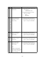
¡(S-4 ) Hardware Checking Menu
This menu is used to check whether there is trouble in image memory (frame memory ).
Possible to check separately the address busandthedatabusforimagememory.
Use this function when color skipping occurs or when the normal printing of the
transmitted image becomes impossible.
Address Check
EXE: Start
Check whether the connection ofaddress bus is normal.
Data
Check whether the data transfer is normally done when reading
/writing onto the frame memory.
It takes severalminiutes to finish
Check
EXE: Start
(S-5 ) Card Ejection Setting Menu
This menu is used for setting the positions of card ejected/rejected.
'Stuck Position'
***********
Designates the place of ejection of the normally finished card.
Left (default ): Ejectionblock
.
Right
'Reject Position'
***********
'Select Action'
***********
'Print Number '
***********
'Card Pass Test'
EXE: Start
: Rejection block
Designates the place of ejection of the card finished in error.
Right (default ) : Rejection block
Left
: Ejection block
Designates the action pattern of card transportation
Card Stack : Transporta card to exit wheredesinated at
"Stack Position" menu.
Card Reject : Transport a card to exit whredesinated at
"Reject Position"menu.
Designates the Number of card transportation action
EXE: Increment of value
CLR:Decrementofvalue
Executes the card transportation action which desinated
at 'Select Action'menu.
3-15
¡(S-6 ) UserModeItems Setting Menu
This menu is used for setting the limitation on some items displayed in USER MODE.
Ribbon Menu Disp
Permit/Prohibit of "Ribbon Type" in the User Mode.
(on/off )
Adjust Menu Disp
Permit/Prohibit of "Color Adjustment"intheUserMode.
(on/off )
Status Menu Disp
Permit/Prohibit of "Printer Status" in the Use Mode.
(on/off )
¡(S-7 ) Encoderrelated Menu
This is the menu to check operation of the optional Encoder. Mainly used for checking
encode operation when trouble shooting.
Encode Operation Menu
This menu is for encoding. Different encode data is created in the Printer at each
operation so that the erroneous recognition at verification will not occur when
pre-encoded card is used.
ISO Track 1 Hi-Co
EXE:Encode
Coresivity
Track to check
Track Setting and Checking DATA
ISO Track1 : Encode on ISO Track 1 (76 Characters )
ISO TRACK 1 ENCODE TEST. ARTLAND COLOR PRINTER PR5100 TOTAL
NO. = ********
ISO Track2 : Encode on ISO Track 2 (37 Characters )
123456789012345678901234567==********
ISO Track3 : Encode on ISO Track 3 (104 Characters )
1234567890123456789012345678901234567890123456789012345678901234567890123
45678901 2345678901234==********
Coercivity
HICO
LOCO
: Encode with high Coercivity (Hi-Co )
: Encode with low Coercivity (Lo-Co )
If encoding is done normally, 'Data Write OK' is displayed in the second line.
Press CLEAR or EXE key.
If error occurs during operation, error LED turns ON and the nature of the error is
displayed on the Operation Panel. Clear the error by pressing CLEAR key.
3-16
¡(S-8 ) Heat Roller related menu
This is the menu for adjusting and checking operations which are related to Optional
Heat Roller. Mainly used for checking Heat Roller operation when trouble shooting.
(
Menu to display total ON time of the heater Total Heat Time
Displays the total ON time of the heater of the Optional Heat Roller.
The displayed unit is hour. The number changes when the power is turned ON.
Heat Total Time
******
Heat Roller Position Adjustment Menu
Heat Position Adjustment
(
This is used to adjust the printing position of sub scanning direction of the Heat Roller.
Range of adjustment is } 35. The setting value is same as the resolution of the printer;
1 value = 1 dot = 25.4mm/300 =0.085mm.
Position Adj.
-35 ~ 35
Adjustment of print position for sub scanning direction.
Increment of value is to move print position to the right.
Position Adj
EXE:Test Print
Print the pattern to check the position of printing the ribbon
set in a Heat Roller unit.
Sensivity of a sensor in Heat Roller adjustment Menu Sensor Adjustment
SensorAdj.
EXE: Start
To adjustthesensivity level of the sensorforleadingedge of
the each panel of the ribbon in Heat Roller.
Accordint to the result of the adjustment, message shown below
will beappeared on lower part of the LCD panel.
' COMPLETE *** ' : Finished normally. *** means the valu of D/A output
' : There an object at the sensor. Rmove the object and retry.
' : An error has occured while adjuting . Go back to Main
Menu and recover .
' DISABLE
' ERROR
3-17
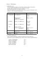
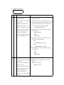
3.3.4 Description of Printer Status
In the User Mode, PrintModeisforthemenutosetthePrinteroperation.
The setting items in this menu are mainly dependent on the application of the Printer.
Follow the system operation manualforthesetting.
Refer to Section 4-b and 4-c of the operation manual of PR5300 for the method of
setting. Description of the setting of Print Mode is included in the returned information
againsttheSCSIsettingstatusrequest command.(Printer System Information ) Refer to
Section 3 - 6 of Command Specification of PR5300.There are following 6 kinds of
setting items.
1. Memory Mode
This is for setting image memory of the Printer. The setting can be switched by the
SCSIcommand. Refer to Section 4-17, Memory Mode Setting Commands, of the
Command Specification of PR5200.
Ring.M Auto clr:
One side alternative receive, memory auto-clear permitted
Ring.M DataHold:
One side alternative receive, memory auto-clear prohibited
Ring.M DualSide:
Both side receive together, memory auto-clear prohibited
Single DataHold:
One side receive only, memory auto-clear prohibited
Economy Dualside:
One side receive together, memory auto-clear prohibited
Default setting is 'Ring.M Auto clr'.
2. SCSI I D Select
Sets the SCSI ID of the printer. After setting, please reset the printer.
Default is "4".
3. Parity Set
Use this for setting parity check function for SCSI communication.
OFF: No check parity.
ON:
Check parity.
Default setting is'OFF'.
4. Encode Type
Sets HICO/LOCOforwriting the magnetic encoding. This is shown only when
the encoder has the function of switching HICO/LOCO.
Default is "LOCO".
5. Encode First
Set the priority for encode operation or print operation.
This is shown only when the encoder unit is connected.
OFF: Print operation ( and other operation with optional units ) first.
ON:
Encode operation first.
Default setting is 'OFF'.
3-18
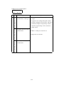
6. Encode Mode
Set the card transportmodefor encoding operation. Refer to Section 3-6 of
Command Specification of PR5100 regarding the relation of each encoder
type and the side of the card with magnetic stripe.
A (Back Side ) : Encoding is done on the back of the image side.
B (Front Side ): Encoding is done on the same side as the image side.
Default setting is 'A (Back Side )'.
7. Exe Key Print
Set the functions of EXE key when the Printer is ready. Refer Section 4
of the Operation Manual of PR5100.
OFF: No function is assigned to EXE key when Printer is ready.
ON: Print function is assigned to EXE key when the Printer is ready.
Printing operation is done by the print information which is
stored in the Printer.
Default setting is 'OFF'.
Note:In the memory modes other than "Ring.M Dual Side" and "Economy Dualside"
and in the case of re-printing of the both side print data, the frame which has
been received at the last time only will be printed. This is because there is no
such idea as the data of front and back sides makes one frame when receiving
the both side data in these modes.
For the other modes than the above, basically selectthesettingof"OFF".
8. Print Retry
This is to set the function to automatically reprint when an error occurs while
printing.
OFF: Returns to ready condition after releasing error.
ON:
After releasing error, prints again the print information
stored in the Printer.
Note: In the memory modes other than "Ring. M Dualside" and "Economy Dualside"
and when retrying the both side print data, only the frame which has become
an error will be printed.This is because there is no such idea as the data of
frontandbacksidesmakesoneframewhen receiving the both side data in
these modes.
For the other modes than the above, basically selectthesettingof"OFF".
9. Parallel Print
When receiving the print command of more than 2 cards, the printing of 2 cards are
processed in parallel. This function allows to shorten the processing time when
printing the cards with plural processing such as magnetic encode, image printing,
and heat roller, etc. Defaultis"OFF".
3-19
10. Card Eject Face
Desinates the side of the card which ejected after printing.
Default setting : Card Face Up
Card Face Up
Ejectthecardwiththesidewhichissetasupinfeeder
block.
On single side printing: Printing side up
On dual side printing : First pring side up
Card Face Down
EjectthecardwiththesidewhichissetasdowninFeeder
block.
On single side printing: Printing side down
On dual side printing : First pring side down
No Effect
Ejectthecardwiththelastprintingsideup
On single side printing: Printing side up
On dualsideprinting : Last printing side up
In case of the printing which includes flip-turn action more than twice, same as
dual side printing mentioned above.
Set as 'No Effect' when need compatibility to PR5100 and/or P5200
10. Print Area
Setthemaximum print area.
Default setting : Edge to Edge
Edge to Edge
Print on the whole area of the card
0.5mm Margin
Print on the entire area excluding 0.5mm non-printing area
from all edges of the card.
Itwould happen nottoprintcrrectlyontheedge(s )of a card caused by card itself
such as curl, dull edge and so on.
3-20
3.4 Structure of Service Mode Menu
Ready toPrint
AdjustmentMode
EXE:sub menu
ODAdjustment
EXE:sub menu
OD Adj Color
Zero Adj Color
OD Adj Black
Zero Adj Black
OD Adj Clear
Zero Adj Clear
Color Adjustment
EXE:TestPrint
Black Adjustment
EXE:TestPrint
ReturntoParent
Menu
Position
Adj.
EXE:sub menu
Holizontal Adj.
Vertical
Adj.
Black Shift Adj.
Position Adj .
EXE:TestPrint
Black Shift Adj.
EXE:TestPrint
ReturntoParent
Menu
Uniformity
Adj.
EXE:sub menu
Uniformity Lower
Uniformity Center
Uniformity Upper
UnifomityAdj.
EXE:TestPrint
ReturntoParent
Menu
ExpandedDt Sdj.
EXE:sub menu
Data CutEnable
on/off
Returntoparent
Menu
LCD Adj
EXE:sub menu
LCD Adj
Returntoparent
Menu
SensorCheck
EXE:sub menu
SN 01 0 2 0 3 0 4 0 5
* * * * *
SN 06 0 7 0 8 0 9 1 0
* * * * *
SN 11 1 2 1 3 1 4 1 5
* * * * *
AutoAdjustment
EXE:Adj. Start
ReturntoParent
Menu
Actuator Check
EXE : sub menu
Pickup MTR. (PM1 )
EXE :submenu
Pickup Motor
EXE:******
ReturntoParent
Menu
RibbonMTR. (DM1 )
EXE : sub menu
RibbonMTR (DM1 )
EXE :******
ReturntoParent
Menu
Headup MTR (DM1 )
EXE : sub menu
Headup MTR (DM1 )
EXE :******
ReturntoParent
Menu
F.Turn Ang. (PM1 )
EXE : sub menu
F.Turn Ang. (PM1 )
EXE :******
ReturntoParent
Menu
F.Turn Trf. (PM2 )
EXE : sub menu
F. TurnTrf. (PM2 )
EXE :**** ****
ReturntoParent
Menu
Print T r f (PM3 )
EXE : sub menu
PrintMTR (PM3 )
EXE :**** ****
ReturntoParent
Menu
ReturntoParent
Menu
Hardware Check
EXE : sub menu
Address Check
EXE:start
Data Check
EXE:start
ReturntoParent
Menu
3-21
Eject Position
EXE : sub menu
StackPosition
**************
Reject Position
**************
Select Action
**************
Print Number
***
CardPassTest
EXE:Start
ReturntoParent
Menu
User Menu Config.
EXE : sub menu
RibbonMenuDisp.
on/off
Adjust Menu Disp.
on/off
StatusMenuDisp.
on/off
ReturntoParent
Menu
Encoder Check
EXE : sub menu
**************
EXE:Encode
ReturntoParent
Menu
Heat Roller Check
EXE : sub menu
Heat Total Time
****
Position Adj
***
HeatRollerTest
EXE:Print
Sensor Adj
EXE:Start
ReturntoParent
Menu
ReturntoNormal
Menu
3-22
Section 4 Maintenance
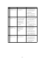
4.1 Maintenance List
To keep the optimum performance of the Printer, periodic maintenance operation is
necessary which is described in Section 6, Cleaning and Section 7,
Periodic replacement Parts in the Operation Manual.
Thissection describes the items which may be required to perform considering the user's
situation, as well as cleaning and replacements.
Section
Rubber Roller
Cleaning Roller
Maintenance
Tools
Every 2,000 frames
Philips screw driver, Soft Cloth
Alcohol
Replaceasrequired
( 40000 frames )
Symptom: Poor transportation
Philips screw driver
Print Roller
Cleaning, every 10000 frames
Soft Cloth.
Alcohol
Feed Roller
Cleaning, every 10000 frames
Soft Cloth.
Alcohol
Other
Cleaning, as required
Symptom: Poor transportation
¤ Trouble shoot
Pulley Shaft
Head Holding
Roller Shaft
Philips screw driver,
Swab
Alcohol
Flat-head screwdriver,
Grease ( Molycoat )
Flat-head screwdriver
Grease ( Molycoat )
Apply Grease, as required
Symptom: Noise
Apply Grease, as required
Symptom:
4. 2 Method of Maintenance
In this section, the maintenance method is described for the items listed in the
maintenance list. For the following items, read the relative sections of Operation Manual.
Cleaning
Replacing
Cleaning
Cleaning
Cleaning
Replacing
Cleaning Roller
Cleanig Roller
Print Roller
Feed Roller
Print Head
Print Head
Sec. 6
Sec. 7
Sec. 6
Sec. 6
Sec. 6
Sec. 7
4-1
4.2.1 Cleaning Rubber Roller
This printer has several sets of rubber rollers to ensure high reliability of card
transportation. However, if the rollers are stained because of use ofstained cards or
cards coated with special materials, transport error may occur due to reduced
transportation power. Though periodic cleaning of rollers may be performed by users
with a certain level of experience, the following intensive cleaning should be done if
such transportation error occurs.
@ Transport Rollers in Flip Turn Module
Open Top Cover and rotate Turn Module so that the rollers
come to the position where the cleaning can be done easily.
¤ This operation is done with the green knob in the flip turn module.
Press a soft cloth with alcohol to the rollers and rotate them.
¤ This operation is done by rotating Green handle located at inside of
side plate.
A Transport Rollers
Open the left cover and insert a soft cloth with alcohol and pressagainst rollers
and rotate them.
¤ This operation is done with Cleaning Knob located on the Front
Access Panel.
!
4-2
4.2.2 Applying grease to Pulley Shafts etc.
Plastic rollers used in this Printer is made of self-lubricative plastics.
On the shafts ofrollers which are loaded with torque and has friction with shaft, grease
is applied at the factory. Although further greasing in notrequired for normal usage,
grease should be applied in case following parts are replaced forsomereasonor
abnormal noise is detected.
Part No.
PR5100P245
PR5100P218
PR5100P220
PR5300P292
PR5300P290
PR5300P289
PR5300P243
PR5300P242
PR5300P034
Name
PUSH-ROLLER
PLY S2M-22-60
PLY S2M-16-70
PLY S2M-59-G-0.8-24
PLY S2M-20-G-0.8-50
PLY S2M-56-G-40
GER-1.0-14-0.8-56
GER-1.0-28
HEAD-PRESS-IN-BKT
4-3
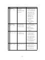
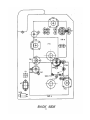
Section 5 Replacement and Adjustment
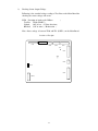
5.1 Replacing Main Board (PBA-MAIN )
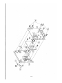
Step 1: Remove R-COVER
Step 2: Loosen two screws on the lower edge and remove two screws on the upper
edge of MAIN-BOARD-PLT and remove a screw to fix the erth cable ,
Then, lean the board backward.
Step 3: Disconnect all harnesses fromtheboard. (CN1 - CN12 )
Step 4: Remove Main Board. ( 7 screws )
Step 5: Fix new Main Board onto the Printer (7 screws ) and connect all harnesses.
Step 6: Make sure thattheSW1issetasNORMALMODE.
Step 7: Raise the MAIN-BOARD-PLT and fix with screws. (4 screws )
Step 8: Attach R-COVER.
Step 9: Turn ONthepowerandmakedownloading
Download the resistance data of print head first.
Then,:
Adjustment of Print Position, Print Uniformity, Print Density.
Adjustment of Sensor levels.
Settings to be done in User Mode Buzzer ON/OFF etc.
Note: Turn OFF all Sysytems connected each other including PC when performing this operation.
CN 5
CN 7
CN8
CN6
CN2
C N1
SW 1
CN4
CN11
CN3
CN1 0
5-1
(
5.2 Adjustment after Main Board replaced.
In the memory on the Main Board, the adjustment values for the printing operation are
stored. Therefore, when replacing the main board, the adjustment in the following steps
are necessary.
It is advisable to memorize these adjustment values before beginning the replacement
work so that the values can be used for the new board.
If there is a difference in the print quality between before and after there placement of
the thermal head, adjust as following.
For the details of the operation panel, please refer to Section 3, Operation Panel.
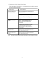
Items to be adjusted in the Serviceman Mode
Adjustment Items
Main Board
Replacement
Thermal Head
Replacement
Print position
Print uniformity
Print density (Color )
Print density ( BK )
Sensor (SN10 ) level
: Necessary
¢ : Depending on the print result
w : Unnecessary
Items to be set in the UserMode
Setting Items
Ribbon Type
ColorAdjustment
Buzzer
Memory Mode
SCSI ID
Parity Set
Encode Type (Note )
Encode First (Note )
Encode Mode (Note )
EXE Key Print
Print Retry
Parallel Print
Main Board Replacement only
(
Setting
Setting the ribbon type to be used
Setting the colorforcolorprinting
Setting buzzer for theoccurrenceoferror
Setting the image memory
Setting SCSI ID number
Setting the parity check of SCSIcommunication
Setting the type of magneticencoding
Setting priority of encoding or printing
Setting the card insertion direction to theencoder
Setting the printing by EXE key
Setting automatic retry at the errorrecovery
Setting parallel processing
Note: Setting of the encoderrelated items can only be made for the device
with the built-in encoder.
5-2
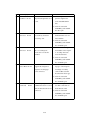
5.2.1 Adjusting the Print Position
When main board is replaced, check and adjust the print positin in the following
procedure.
Step 1. Print Test Pattern H in the "Position Adjustment" menu of Service Mode.
Step 2. Adjust HorizontalandVerticalvaluesso that dimensions h and v
(distance from the edge of card ) become 0.5 +/-0.2mm.
Step 3. Print the Test Pattern H again and confirm the h and v dimensions.
Repeattheaboveifnecessary.
Note 1: Ifh,v,issmallerthan0.5mm,increase the setting value.
If h, v, is larger than 0.5mm, decrease the setting value.
Note 2: Setting value can be calculated in the following formula.
H'= H + (2-h )/12
H' : New setting value ( Horizontal )
( " "
)
H : Current value
h :measured valu ( mm )
V' can be obtained in the same formula.
Note 3: Start adjustment with the current value (value before replacing
Thermal Head) retained.
Test Pattern H
5-3
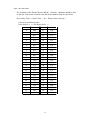
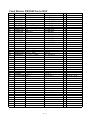
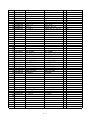
<mm - dot conversion >
The resolution of the Thermal Head is 300 dpi. Therefore, adjustment should be done
in this unit. Convert the measured value into the dot number using the table below.
New Setting Value = Current Value + (0.5 - Distance from card edge )
Convert by the following table.
If the distance is (- ), dot should also be (- ).
0
0.00
26
2.20
1
0.08
27
2.29
2
0.17
28
2.37
3
0.25
29
2.46
4
0.34
30
2.54
5
0.42
31
2.62
6
0.51
32
2.71
7
0.59
33
2.79
8
0.68
34
2.88
9
0.76
35
2.96
10
0.85
36
3.05
11
0.93
37
3.13
12
1.02
38
3.22
13
1.10
39
3.30
14
1.19
40
3.39
15
1.27
41
3.47
16
1.35
42
3.56
17
1.44
43
3.64
18
1.52
44
3.73
19
1.61
45
3.81
20
1.69
46
3.89
21
1.78
47
3.98
22
1.86
48
4.06
23
1.95
49
4.15
24
2.03
50
4.23
25
2.12
5-4
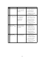
5.2.2 Adjustment of Print Uniformity
When the main board is replaced, check and adjust the print uniformity in the following
procedure after adjusting the pring position.
Step 1: Print Test Pattern H in "Uniformity Adjustment" munu of "Service Mode".
Step 2: Compare print density of the following three positions A, B, C, and decrease
the densities of two positions to the same as the least dense position.
Step 3: Print Test Pattern H again and check the density of the three positions.
Adjustagain if necessary.
Note 1: Use density meter to compare the densities. If the instrument is not
available, check visually.
Note 2: Three positions A, B, C, correspond to the positionsshownontheOperation
Panel as following:
A: Upper
B: Center
C: Lower
Note 3: Start adjustment with the current value (value before replacing Thermal
Head) retained.
Test Pattern H
5-5
5.2.3 Adjustment of Print Density
When the main board is replaced, check and adjus the print density in the following
procedure after adjusting print position and print uniformity.
Adjustment of Image and Protective Layer
Step 1: Print Test Pattern J in "OD Adjustment" menu of "Service Mode".
SteP 2: Change "Color" Setting Value so thatthereisnocolordropoffandthe
average density of Positions A, B, C, becomes within 1.65 +/-0.05.
Step 3: If the starting portion of Protectiv Layer is not printed, increase value of
"Clear". ( Caution: Do notsettoolargevalue because it may cause a trouble. )
Step 4: Print Test Pattern J again to check the densities of A, B, C. Adjust again if
necessary.
Note 1: Use density meter to compare the density, If instrumentisnotavailable, use
sample card and compare visually.
Note 2: The larger the "Color" value, the higher the density becomes.
Note 3: Start adjustment with the current value (value before replacing Thermal
Head ) retained.
Test Pattern J
5-6
Adjustment of BK
Step 1: Print Test Pattern E in "OD Adjustment" menu of "Service Mode".
Step 2: If there is a drop off in the image, increase the setting value. Conversely, if
the image is too thick and lines toutches each other, decrease the value.
Step 3: Print Test Pattern E again and check the print condition. Adjust again if
necessary.
Note 1: Start adjustment with the current value (value before replacing Thermal
Head) retained.
Note 2: As to the operation of the Operation Panel, refer to Section 3
"Operation of Operation Panel".
Test Pattern E
5-7
5.2.4 Adjustment of Sensor Level
Adjustable sensors of the Printer are factory adjusted atthetime of shipment.
Readjustment is necessary in the following case:
Sensor is replaced. light source, receiver(
Mechanically changed affecting the light axis.
Main Board PBA-MAIN (is replaced. )
Ribbon related error occurs frequently.
)
If the sensor output voltage is below the specified value in spite of the adjustment
according to correct procedure, repair the defective parts as instructed in paragraph 3.
Note: Adjust the sensor outputlevelat where the external light will not affect.
When measuring the output voltage of the sensor with volt meter, use the meter
at 0.1V range.
1) Automatic Adjustment of Sensors
Step 1: With the power OFF, visually confirmthat there is no card in the Printer.
Step 2: Open Ribbon Cover and pull out the Ribbon Cartridge.
Set the Ribbon Cartridge again in the position so that Yellow Part of the
Ribbon comes to block the lighttoSN10andclosetheRibbonCover.
Step 3: Turn ON the power and execute "Sensor Auto Adjustment" menu in
"Service Mode".
Step 4: Finish "Service Mode".
Note:
Refer to Sec. 3 "Operation of Operation Panel".
5-8
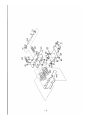
2) Checking Sensor Output Voltage
Following is the standard voltage reading of Test Pins on the Main Board for
checking the sensor voltage with tester.
( of mark on the Ribbon
)
SN10 Detection
Test Pin: TP20(SN10PT )
Lighted: 1.0V or less ( Yellow detection )
Blocked: 3.0V or more ( Bk detection )
Note: Above voltage is between TP20 and TP1(SGND ) on the Main Board.
Location of Test pins
CN5
CN7
CN8
CN6
CN2
TP1
CN1
TP20
CN4
CN11
CN3
CN1 0
5-9
3) Countermeasure for the Abnormal Sensor Output
If the sensor output as described in 2) is not obtained, locate the defective partand
repair in the following procedure.
Possible Defect
Defectiveconnection of
harness and Printed
Printed Circuit Board.
Check and Repair
Check contctsofallconnectorswhichconnects
the boardswithlightsources and sensors to
the Main Board.
Check the contact of each harnesswithcircuit
testerfollowing the circuit diagram and if
defectiveconnection is found, replace the
harness.
Defective mounting o f
sensor.
Check mounting of the lightsourcesand
sensors. If incorrectmounting angle of
sensor or loose screw is found,correct
the mounting.
Confirm that the light emitting faceandthe
receiving faceofthesensorsare facing
directly and there is nothing in between to
block the light.
Defective sensor.
Replace the sensor (light emitterandreceiver )
and confirm normal operation.
Defective Main Circuit
Board.
Replace the Main Circuit Board (PBA-MAIN )
and confirm normal opration.
Note: Turn OFF the power when checking connection of harnessandreplacing parts.
5-10
5.3 Adjusting density of LCD Display
Density of LCDDisplay on the Operation Panel Board (PBA-OPEPANE ) is adjusted
to the optimum when shipping fromfactory. However, it can be adjusted by the user in
the following procedure.
Step 1: Turn ONthepowerandget the LCD Adjustment in Service Mode.
Step 2: To make the density higher, press EXE key
To make the density higher, press EXE key
5-11
5.5 AdjustmentforCardThickness
Adjustment of Gap of Separation Gate
Step 1. Open cover of Card Suply Box, loosen 2 screws (M3 x 8 ) fixing the Gate and
lift the Gate.
Step 2. Insert a flat plate 'having about 1.5 times of thickness of the card' beneath the
middle of the gate and press down the Gate and tighten the screws.
Step 3. Remove the plate.
Loosen two screws
5-12
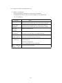
Section 6 Troubleshooting
This paragraphdeals with the causes and countermeasures for various troubles which
may occur with the printer system.
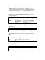
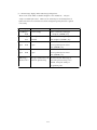
6.1 Troubleshooting with the display ontheLCD.
Whenatroubleisdetected,theerrorindication LEDon the operation panel is
turned ON and the type of the trouble is shown on the LCD. In this section, the cause and the
method ofrecovery are explainedbased onthedisplay ontheLCD.
The type of the error is indicated withthe two digit of error code Er
and two digit of
details code(Ad ).
On the LCD panel, it isshownwitherror message (16 digits x 2 lines:corresponding to the
errorcode ) and four digit numbers ( 2 digits :Er and 2digits:Ad ) onthelowerrightcorner.
exsample
In this case
Front Cover is
Error Code (Er )
Open
Details Code (Ad ) : 01h
12-01
: 12h
The details code may be indicated with thewild card (** ) in this paragraph.
User operates the errorrecovery steps basedon the error message on the LCD panel. Most
of the errors canberecovered by the user. However, in case of unrecoverableerroror
frequent errors, the service personmust be called.
When there is a service person call from users, please ask to inform detailed symptoms, error
message anddetailscode.
6-1
6.1.1 Displayon theLCD and methodofrecovery
(1 ) Display of normalstatus
The followingdisplays ontheLCDarenormalstatus of theprinter.
To distinguish from theerror, the error indicationLED is not lit andthedetails
code is not displayed.
LCDDisplay
Ready toprint
Status
The printer is at the waiting status (normalstatus ).
Itispossibletotransferthedatafrom the hostcomputerandprint.
Ready toprint.
The print headisliftedandtheribbon cassette can be removed.
-Headupside-
Itispossibletotransferthedatafrom the hostcomputer and print.
Please wait...
Printer is beinginitialized.
Initializing
Please wait...
Printer is processing the printing job. Depending on the setting of the
Nowprinting
memorymode, the data transfer is possiblein this status.
Please wait...
HeatRoll Warm Up
Ready to
Optional heat roller unit is being warmed up.
This indicates that the booting as safety mode because the main
Down load
programisdamaged .
Download the mainprogram.
Pleaseread paragraph 7 for the downloading.
HOST -> Fl Memory This indicates that now loading.
Loading
.....wait
6-2
(2 ) Messages topromptmanual recoveryfromthe error
The following messagesshowsthestepsofmanualoperationto recover.
When the [CLEAR ] key is pressedafterthe error, the printer does the recovery
operationifthe conditions for recovery are met. If not, oneof the followingmessages
will be shown. There is nodetails code. ( This shows the condition forrecovery
onlyand does not indicateoccurrenceof anyerror.)
If [CLEAR ] key is pressedwhile "RibbonEmpty" or "RibbonTake Up"error, the
following messageisshown:
LCDDisplay
Status
Recovery Method
Check Ink
CLEAR] key is
Take outtheribbon cassette and
Ribbon
pressed while Ribbon
checkthe status of the ribbon. Then,
Empty orRibbon Take
closethe Front Access Cover and
Up error.
press [CLEAR ] key.
If the [CLEAR ] keyispressed whilethere is "CardEmpty"error,the following
message isshown:
LCDDisplay
CardEmpty
Status
RecoveryMethod
[CLEAR ]key is pressed
while there is no card.
Setthecardsinthecardhopper
and press [CLEAR ]key.
If the [CLEAR ]keyispressed whilethe Front Cover is open, thefollowingmessage
is shown:
LCDDisplay
Status
Recovery Method
Front Cover is
CLEAR]key is pressed
Closethe Front Access Cover and
Open
while theFrontCoveris
press [CLEAR ] key.
open.
If the [CLEAR ]keyispressed whilethe TopCoverisopen,thefollowing message
is shown:
LCDDisplay
Status
RecoveryMethod
Top cover is
[CLEAR ]key is pressed
Closethe SideAccess CoverandTopCover
open
while theFrontCoveris
Thenpress [CLEAR ] key.
open.
6-3
If the [CLEAR ] key is pressed while the card is insideeventhough to try to eject a card
automaticaly, theforrowing message is shown:
LCDDisplay
Status
RecoveryMethod
Card J a m
[CLEAR ]key is pressed
Turn power off and remove the card
Remove the card
while a cardisremaining
manually. See the operationmanualforhow
inside of a machine
to remove the card.
Turn power on .
If the [CLEAR ] key is pressed while the Print Head resistance data has not been
loaded.
LCDDisplay
Status
RecoveryMethod
Resist Data is
[CLEAR ]key is pressed
Download the resistance data of which the
notloaded
while theDataisnot
ser.# is matchedtotheser.#oftheprint
installed
head. See the operation manual Section 7
for downloading.
If the [CLEAR ] keyispressed while there is an "Unrecoverable error", the following
message isshown:
LCDDisplay
Status
Recovery Method
Can not Recover
CLEAR] key is pressed
Turn OFF and ON the power, or
Please Reset
hile there is an
execute RESET ontheoperation
unrecoverable error.
panel.
6-4
(3 ) Error message display inthenormalusageoftheprinter
These are the errors which occurwhiletheprinter is in normal use. Theyare
easily recoverable bytheusers. However, the errors may be erroneouslydetected
bythesensordefectives.Insuchcase,thecheckingand repair by theservice person
is necessary.
LCDDisplay
CardEmpty
Status
RecoveryMethod
Card is empty.
Setthecardsinthecardhopper
16-01
RibbonEmpty
and press [CLEAR ] key.
Printing Ribbon i s
Set newribbonin the printing
finished.
block andpress [CLEAR ] key.
Front Cover is
Front Access Cover is
Checkthat theFrontAccess
Open
open.
Cover is positivelyclosed and
19-0
12-01
press [CLEAR ] key.
Top Cover is
Front Access Cover is
Checkthat theFrontAccess
Open
open.
Cover is positivelyclosed and
14-01
press [CLEAR ] key.
RibbonType
The type ofribbondoes not Checkwhetherthe ribbon type is
Incorrect 1A-**
match the printersetting.
sameastheprintersetting.ifit is
different, changethe setting of
the operation panel.
6-5
(4 ) Card jamrelated Error messages
Cardjamerrorsoccur when the card is nottransported intheprinter system as the
sequence. The basic recovery steps for the card jamerrorsaredescribedbelow.
The card jam errors may be causedbythecardsbeingused.Checkif there is any
problem onthecarditselfsuchasthespecification (thickness,size,etc. ), bend,
surface finish ( anti-static treatment, specialfinish,etc. ).
LCDDisplay
Status
Recovery Method
CardJam.Feeder
Card is notfednormally
Area-
from the cardfeeder.
**-**
Check whether the cards are set
correctly in the cardfeederand
press [CLEAR ] key.
Press [CLEAR ] key. Ifimpossible
CardJam.F.Turn
Card transportation
Area--
error intheflipturnblock.
**-**
to recover, checking and repair by
service personisnecessary.
CardJam.Print
Card transportation
Press [CLEAR ] key.
Area--
error intheprintblock.
Ifimpossible to recover, check
**-**
and repair by theservice person
is necessary.
CardJam.Encode
Area--
**-**
Card transportation
Press [CLEAR ] key. Ifimpossible to
error intheEncoder
recover, checkandrepairby the
Unit.
service personisnecessary.
Note ) For details, refer to the
Service Manual of the Encoder Unit.
6-6
(5 ) Error messages of the internaltroublesoftheprinter.
The following is the error messages of the internaltroublesoftheprinter system.
Most of those troubles needs the check and repair bytheservice person.
LCD Display
CardJam.
Unknown
Status
Recovery Method
An unexpectedcard has
**-**
beendetected.
TurnOFFthepower and
remove the cardmanually.
Ifthiserrorrepeatsafterthe
aboveoperation, checkand
repair bytheservice person is
necessary.
Ribbon Wind Up
Quickly
Ribbon wind uperror.
1B-01
Check thattheribbon is set
correctly andpress [CLEAR ] key.
Ribbon Wind UP
Slowly
1C-01
Service ManCall
errorCode **-**
Thereisanunrecoverable
error intheprinter.
TurnOFFandONthepoweror
execute RESET. Iftheerrorrepeats,
check andrepair bytheservice person
is necessary.
(6 )Other paticularerror
In case of dualsideprinting:
If a printingprocess is suspendedbysomeerrorsuchascardjam,itmaynotbecontinuing
theprocess of the data for another side . Inthiscaseitwillbecreatedtheerrosasfollows.
LCDDisplay
Status
Recovery Method
PrintCard does
Itcannotcontinuethe
notExist 5F-**
Printing since the card h a s
finished aserror.
ejected.
Reissue the card .
6-7
The process of printingdatawillbe
6. 1. 2 Checkingandrepairingofthe hardware relatedtroubles.
Please check and repair inthefollowing steps whentheerrorsarenotreovered bytheusers.
< Note > Read the following without fail before troubleshooting.
There are Error Message, Error Code,andDetailsCodeforeacherrors.
ETo finddiagnosis formtheLCDDisplay,usethecombinationof Error Message
Error Code (Er ) and Details Code (Ad ).
EUse the combinationofErrorCodeandDetailsCodeforcheckingthecontentsof
the error log.
Donotforget toturnOFF the power switch and disconnectthepowercordbefore
performingthe following operation.
E Replacingthe thermal head.
E Removing thefrontorbackcoveroftheprinter.
E Checking connection of the harnessetc.
E Replacingthe parts of PCB,sensor,motor,etc.
E Installingor dismounting the Encoder Unittotheprinter.
E Connecting the optional units.
E Removing thecoveroftheoptionalunits.
*To use the sensor check mode to check the sensor operation with thecoverremoved,please
be careful nottotouchthePCB.Itmaycauseatrouble.
As itisdangerous,please carefullyoperate the operation panel nottomoveinto
other mode thanthesensorcheck mode.
CardJamErrorsaredetected bythesensorslocated alongthecardpath,and
classified intwocategoriesaccording tothecause.
E Un-arrival Jam: In the cardtransportation, the card i s n o t d e t e c t e d a t a
specifiedposition after a specified time.
E StayingJam:
In the cardtransportation, the cardisstaying at theposition
where it shouldnotstopat. ( Undesired sensor condition ).
If the errorrelatingto the adjustablesensors repeats, the incorrect setting of the
sensor is doubted. Readjustthesensorsensitivitiesfollowing theinstruction inthe
paragraph 3.
E SN11 Ink ribbon end sensor.
When checking the various actuators, please checkthat nocard is remaining in
the printer. If the independent checking operationis done while thecard is
remaining, it may cause other trouble.
Please follow the steps describedin theparagraph 4, for cleaning of the rubber rollers.
6-8
List of the hardwareerrorrelated error messages
Error Message
Front Cover is Open
Er. Code
11
Ad. Code
01
Top Cover is Open
14
01
CardEmpty.
16
01
RibbonEmpty.
19
01
RibbonTypeIncorrect.
1A
01-03
RibbonWindupmiss.
1B
01-02
Encoder Write Error
73
01-07
11-17
21-27
01-03
CardJAMFeeder Area**
40,41
CardJAMF.Turn Area**
47-4A
CardJAMPrint Area**
50-53
01, 1 0 - 1 6
ff
01, 1 0 - 1 8
ff
10-13
CardJAMEncodeArea**
74,75
PrintCarddoesnotExist
5F
CardJAM. Unknown
Temperature out ofRange
28
29
2D
32
01-06
01-04
01-03
01-03
EncoderI/FError
77
10-15
Service ManCallErrorCode
20
21
24
30
31
33
70
71
72
C0
C1
C2
C3
38
39
3A
3B
3C
6-9
01-04
01-03
01-04
01-02
01-03
01
01-10
01-03,0f
ff
01-04
01-02
01-02
01
01
Particular
Particular
Particular
Particular
Particular
Page
(1 ) Card Empty
Card Empty
Er-Ad
Er
Ad
16
01
Symptom
Card is not s e t i n t h e
feeding block.
Ifitbecomeserrordespite
Check/Repair
(1 ) Checkthe reactionofSN1intheSensor
CheckMode.
(2 ) Ifthesensordoesnotreactnormally,
the cards are set, s e e t h e
check the connection and electric contact of
Check/Repair section.
the harness.
ASM-SENSOR-AE CN101
(
(3 ) Iftheharnessconnection is normal,
replace thefollowing:
ESN-1
EPBA-MAIN
(2 ) Front Cover Open
Front Cover is
Open
Er
Ad
11
01
Er-Ad
Symptom
Check/Repair
FrontAccess Cover opened (1 ) Checkthe reactionofSN13toopen/close
while the printer is idle.
of the Front Cover in the SensorCheck Mode.
Ifitbecomeserrordespite
(2 ) If the sensor does notreact normally,
the cover is closed, s e e t h e
checkconnection and electric contact
Check/Repair section.
of the harness.
ASM-I/L-SWE CN116
12
01
FrontAccessCover
openedwhile the printer is
(3 ) Iftheharnessconnection is not
normal, replacethe following:
in operation.
ESN13
EPBA-MAIN
6-10
(
)
)
(3 ) Top Cover Open
Top
Open
Er
Ad
16
01
Cover
is
Er-Ad
Symptom
Check/Repair
Top Cover opened
(1 ) Closethe Front coverandcheckthereaction
Ifitbecomeserrordespite
of SN14 toopen/close of the Top Cover inthe
the cover is closed, s e e t h e
SensorCheckMode.
Check/Repair section.
(2 ) If the sensor does notreact normally,
checkconnection and electric contact
of the harness.
ASM-I/L-SWE CN117
(
)
(3 ) Iftheharnessconnection is not
normal, replacethe following:
ESN14
EPBA-MAIN
(4 ) RibbonEmpty
RibbonEmpty
**
Er
Ad
19
01
Symptom
Check/Repair
Ribbon Empty markhasbeen (1 )Adjust the sensor SN10in the Sensor Check
detected.If it becomes error Mode. Ifimpossible toadjust,check the connection
despite the
correctly
ribbon
and
it
is
has
set andelectric contact of the harness.
ASM-SENSOR-BE CN111,CN112
not
ASM-LDRELAY2E CN110,CN111
reachedattheemptymark,
see theCheck/Repair section.
(
)
(
(2 )If the harness connection is normal, replace the
following:
ESN10
EPBA-MAIN
6-11
)
(5 ) Incorrect Setting of the RibbonType
RibbonType
Incorrect
Er
1A
Ad
**
Symptom
Check/Repair
01
Distance between the edges of (1 )Clean the ribbon transportrollers.
02
the ribbon is different from (2 )Ribbon Cassette seems to be wrong.
the setting.
Replacethe following:
ERibbon Cassette
03
Impossible to detect
(1 )Checkwhether there is a damage on the ribbon.
Ribbon Edge.
(2 )Adjust thesensor SN10in the Sensor
Check Mode. If impossible to adjust, check the
connection and electric contact of the harness.
ASM-SENSOR-BE CN111, CN112 (
ASM-LD RELAY2E CN110, CN112
(3 ) If the connection of the harness is normal,
replace thefollowing:
ESN10
EPBA-MAIN
6-12
)
(
)
(6 ) Ribbon Take Up Error
RibbonWindup
miss
Er
Ad
1B
01
**
Symptom
Take up speedof the ink
ribbonistoo slow.
Check whether the ribbon is
setcorrectly.
Check/Repair
(1 )Checkreaction of sensors SN8,SN9in
SensorCheck Mode.
If thesensors do notreact normally, go to (2b )
(2a )Ifthereisnoproblem withthe sensors, motors
This error occurs whenthe
are questionable.Check the connection and
ribbonadheres onthecard.
electriccontactof the harness of DM1.
ASM-MOTORE CN122
Check if improper card is
used, suchas double printin
Some materials of thecard
(
(3a )Iftheharness connection is normal, replace
the following:
may cause this trouble.
ERibbon Cassette
Ifthereisnoproblemasabve,
EDM1
see theCheck/Repair section.
EPBA-MAIN
(2b )Checkconnection and electricalcontactof
harnesses of SN8 and SN9.
ESN8
ASM-SENSOR-C (CN113 )
ESN9
ASM-SENSOR-A (CN103 )
(3b )If theharness connection is normal, replace
the following:
ESN8
ESN9
EPBA-MAIN
02
Take upspeed of the ribbon
(1 )Clean the ribbon transportrollers.
is too fast.Check if the ribbon (2 )Ribbon Cassette seems t o b e a c a u s e o f t h e
is correctlset.
trouble.
Ifthereisatearintheribbon,
Replacethe following:
this error occurs.
ERibbon Cassette
Check if theadjustmentofthe
printposition inthescanning
direction isappropriate.
Ifthereisnoproblemas
above,see the Check/Repair
section.
6-13
)
(7 )Magnetic Encoder WritingError
Encoder Write
Error
Er-Ad
Er
Ad
Symptom
73
01
A writing error has occured
02
on ISO track 1 or J I S t y p e 2
Check/Repair
(1 )Check that thecard issetcrrectly in card
hopper.
03
It depends on the settings intheprinter and/or
04
operation ofanapplication toput the card suface
05
of which has magnetic stripesideup or down.
06
Check the magneticstripe of the card meets a
07
writing format.
11
A writing error has occured
12
on ISO track 2
(2 )Make a cleaning on encoder h e a d .
13
14
(3 )Replacethe encoder unit
15
16
17
21
A writing error has occured
22
on ISO track 3
23
24
25
26
27
6-14
(8 ) Card Jam intheCardFeedBlock
CardJAM. Feeder
Area01
Er
Ad
40
01
Er-Ad
Symptom
Check/Repair
Carddoesnot arrive at
(1 )Checkthat thecardisnotarrivedattheSN2.
SN2 while feeding.
If it has arrivedor passedthrough,go to (2b ).
(2a )Checkthe motionofPM1intheActuator
Check Mode. If the motionisnormal,clean the
feedrollers in the cardfeeding blockandadjust
the separationgate.
(3a )Ifitdoes not worknormally,checkthe
connectionofharness.
ASM-MOTORE CN118
(
)
(4a )Iftheharnessconnection is normal, replace
the following:
EPM1
EPBA-MAIN
(2b )Checkthe reaction o f S N 2 i n t h e
Sensor Check Mode.
(3b )If SN2doesnot react, checkthe
connection of theharness.
ASM-SENSOR-BE CN105
(4b )If theharness connection is normal, replace
the following:
ESN2
EPBA-MAIN
6-15
(
)
(9 ) Card Jam intheCardFeedBlock
CardJAM. Feeder
Area02
Er
Ad
41
02
Er-Ad
Symptom
A card jam has occured at
SN2 whilefeeding.
Check/Repair
(1 )Checkthat thecardisstayingattheSN2.
If there is not the card , go to (2b ).
The card has reachedat Cleaning Roller,
there is possibility of transportig motor failure
on Flip Turn Unit.ThenseetheErrorCode
47part.
(2a )Checkthe motionofPM1intheActuator
Check Mode. If the motion is normal, clean
the feed rollers in the card feeding block and
adjust the separation gate.
(3a )Ifitdoes not worknormally,checkthe
connection of harness.
ASM-MOTORE CN118
(
)
(4a )Iftheharnessconnection is normal, replace
the following:
EPM1
EPBA-MAIN
(2b )Checkthe reaction o f S N 2 i n t h e
Sensor Check Mode.
(3b )If SN2doesnot react, checkthe
connection of the harness.
ASM-SENSOR-BE CN105
(4b )If theharness connection is normal, replace
the following:
ESN2
EPBA-MAIN
6-16
(
)
(10 ) Card Jam in the Flip Turn Block
Card
JAM F.Turn
Area02
Er - Ad
Er
Ad
Symptom
Check/Repair
47
01
Cardjam error in the
10
Area02(SN2orSN3 ) when
problem area. Ifthereisnotacard,
11
the card is transported from
goto (2b )
12
Feeder toFlip Turn. block
The card has not reached atCleaningRoller,
(1 )Checkthat thecardisstayingatthe
13
there is possibility offeedermotor failure
14
on FeederBlock . Thensee the Error Code
15
41part.
16
(2a )After removing the card, check the motion of
PM2 in the Actuator CheckMode.
ff
If normal, clean the transport rollers in the flip
turn block and Cleaning Roller then adjust the
separation gate.
(3a )IfPM2doesnotworknormally,check
connection and electrical contact of the harness.
ASM-MOTORE CN119
(
(4a )Iftheharnessconnection is normal,
replace thefollowing:
EPM2
EPBA-MAIN
(2b )Checkreaction of SN2andSN3intheSensor
CheckMode.
(3b )If SN2 or SN3 does not react, check
connection and electrical contact of the
harness.
ESN2
ASM-SENSOR-B (CN105 )
ESN3
ASM-SENSOR-B (CN106 )
(4b )If theharness connection is normal,
replace thefollowing:
ESN2 or SN3
EPBA-MAIN
6-17
)
(11 ) Card Jam in the Flip Turn Block
Card JAM F. Turn
Area03
Er
48
Ad
01
10
11
12
13
14
15
16
ff
Er-Ad
Symptom
Check/Repair
Cardjam error in the
(1 )Checkthat thecardisstayingatthe
Area03 (Flip Turn Unit )
problem area. Ifthereisnotacard,goto (*b )
when it is ejected from Flip
Checkthe angle of Flip Turn unitispsitioned
Turnunit .
correctly towardFeederBlock or Print Block
orMagneticEncoder Block.
If itisnotpositionedcorrectly,seetheError
Code 20 part.
(2a )Afterremovingthecard,checkthe
motion of PM2 intheActuator Check Mode.
If normal,cleanthetransportrollers
intheflipturnblock.
(3a )IfPM2doesnotworknormally,check
connection and electrical contact of the harness.
(
)
ASM-MOTORE CN119
(4a )Iftheharnessconnection is normal,
replace thefollowing:
EPM2
EPBA-MAIN
(2b )Check reaction of SN3, SN4, SN15 (when
encoderconnected ) in the Sensor Check
Mode.
(3b )If there is any sensor which does not
react, checkconnectionand electrical
contact of the harness.
ESN3
ASM-SENSOR-B (CN106 )
ESN4
ASM-SENSOR-BE CN107
(
)
SN15E when (encoderconnected
(
)
ASM-I/F-R/WE CN123
(
)
ASM-ENCE CN123,CN124
(4b )If theharness connection is normal,
replace thefollowing:
ESN2
ESN3
SN15E when (encoder connected
)
EPBA-MAIN
6-18
)
(12 ) CardJamintheFlipTurnBlock
Card JAM. F. Turn
Area04
Er
Ad
44
01
Er-Ad
Symptom
Card jam error in the
Area04 (SN4 ) when i t i s
Check/Repair
(1 )Checkthat thecardisstayinginthe
problem area. If nocard,goto (*b ).
10
transported from Feeder Block (2a )Afterremovingthestaying card, check
11
to Flip Turn Block or from
the motion of PM2, PM3 intheActuator Check
12
FlipTurntoFeeder.
Mode. If normal,clean both the transport
13
rollers of FlipTurnblock and the Print
14
Block.
15
16
(3a )IfPM2andPM3doesnotwork
normally,check connectionandelectrical
contact of the harness.
ff
EPM2
ASM-MOTOR (CN119 )
EPM3
ASM-MOTOR (CN120 )
EPBA-MAIN
(4a )Iftheharnessconnection is normal,
replace thefollowing:
EPM2
EPM3
EPBA-MAIN
(2b )Checkthe reaction o f S N 4 i n t h e
Sensor Check Mode.
(3b )If SN4doesnot react, checkconnectionand
electrical contact of theharness.
ASM-SENSOR-BE CN107
(4b )If theharness connection is normal,
replace thefollowing:
ESN4
EPBA-MAIN
6-19
(
)
(12 ) CardJanintheFlipTurnBlock
Card JAM. F. Turn
Area08
Er - Ad
Er
Ad
Symptom
4A
01
Cardjam error in the
Check/Repair
(1 )Checkthat thecardisstayinginthe
Area 08(SN15 ) whenthe
problem area. If no card, go to (2b ).
10
card is transported from
(2a )Afterremovingthestaying card, check
11
Flip Turn toEncoder orfrom
themotion of PM2, in the Actuator
12
Encoder to FlipTurn.
Check Mode. If normal, cleanthe
13
transportrollers offlipturnblock.
14
Check that there is "Encoder Check" menu i n t h e
15
service mode.
16
If there is not "EncoderCheck"menu, the printer
does notrecognizethe Encoder.
ff
Then see section 6.2 (Errors which can not be
checkedon theLCD panel.)
(3a )IfPM2doesnotworknormally,check
connection andelectricalcontactoftheharness.
ASM-MOTORE CN119
(
)
(4a )Iftheharnessconnection is normal,replace the
following:
EPM2
EPBA-MAIN
(2b )Checkthe reaction o f S N 1 5 i n t h e
SensorCheck Mode.
(3b )If SN15 does not react, check connection and
electrical contact of theharness.
ASM-I/F-R/WE CN123
ASM-ENCE CN123,124(
(4b )If theharness connection is normal,
replace thefollowing:
ESN15
EPBA-MAIN
6-20
(
)
)
(14 ) Card Jam in the PrintingBlock
Card JAM. Print
Area 04
Er-Ad
Er
Ad
Symptom
50
01
Cardjam error in the
Check/Repair
(1 )Checkthat thecardisstayinginthe
Area04 (SN4 ) while the
problem area. If nocard,goto (*b ).
10
card is transported from
(2a )After removing the staying card,check the
11
Print Block to Flip Turn or
12
fromFlipTurn toPrintBlock.
13
14
motion of PM2,PM3 in the ActuatorCheck
Mode. If normal,clean the transport rollers of
Flip Turn blockandthePrintBlock.
(3a )IfPM2andPM3doesnotworknormally,
15
check connection and electrical contact of the
16
harness.
17
EPM2
ASM-MOTOR (119 )
ff
EPM3
ASM-MOTOR (CN120 )
(4a )Iftheharnessconnection is normal,
replace thefollowing:
EPM2
EPM3
EPBA-MAIN
(2b )Checkreaction of SN4inthe
SensorCheck Mode.
(3b )If SN4 does not react, check connection and
electrical contact of theharness.
ASM-SENSOR-BE CN107
(4b )If theharness connection is normal,
replace thefollowing:
ESN4
EPBA-MAIN
6-21
(
)
(15 ) Card Jam in the PrintingBlock
Card JAM. Print
Area05
Er
Ad
51
01
Er-Ad
Card JAM. Print
CardJAM.Print
Area06
Area07
Symptom
Cardjam error in the
Area05(SN4-SN5 ) while th
10
card is transportedin the
11
PrintBlock.
Er-Ad
Check/Repair
(1 )Checkthat thecardisstayinginthe
problem area. If nocard,goto (*b ).
(2a )Afterremovingthestaying card,check the
motion of PM3, intheActuatorCheck
12
Mode. If normal, cleanthe transportrollers
13
of the PrintBlock.
14
52
Er-Ad
(3a )If PM3 does not work normally,
15
Cardjam error in the
check connection and electricalcontactof the
16
Area06(SN5 ) while th
harness.
17
card is transportedin the
PrintBlock.
ff
ASM-MOTORE CN120
(
)
(4a )Iftheharnessconnection is normal,
replace thefollowing:
EPM3
EPBA-MAIN
(2b )Checkthe reaction o f S N 5 i n t h e
SensorCheck Mode.
(3b )If SN5doesnot react, checkconnectionand
electrical contact ofthe harness.
53
ASM-SENSOR-BE CN109
Cardjam error in the
Area07(not at SN5 ) while
ASM-SENSOR-RELAY E CN108,109
the card is transported in the (4b )If theharness connection is normal,
PrintBlock.
(
replace thefollowing:
ESN5
EPBA-MAIN
6-22
)
(
)
(16 )CardJamerrorinEncoder
Card JAM. Encode
Area 08
Er - Ad
Er
Ad
Symptom
Check/Repair
74
10
Cardjam error in the
11
Area08 (SN15 ) while the
12
card is transported from
13
Encoder to Flip Turn orfrom (2a ) Afterremovingthestaying card,
(1 ) Checkthat thecard is staying inthe
problem area. If nocard,goto (*b ).
FlipTurntoEncoder.
checkthe motion of PM2 in the
ActuatorCheck Mode. Ifnormal,
clean the transportrollers of the Encoder.
Checkthe transportrollerworkingnormally.
Ifitdoesnotworknormally,replacethe
Encoder.
(3a ) If PM2 does not work normally, check
connection and electrical contact of the
harness.
ASM-MOTORE CN119
(
)
(4a ) Iftheharnessconnection is normal,
replace the following:
EPM2
EPBA-MAIN
(2b ) Checkthe reaction o f S N 1 5 i n t h e
Sensor Check Mode.
(3b ) IfSN15 does notreact,check connection and
electrical contact of the harness.
ASM-IF-R/WE CN123
(
(
ASM-ENCE CN123CN124
(4b ) Iftheharnessconnection is normal,
replace the following:
ESN15
EPBA-MAIN
6-23
)
)
(17 ) Card Jam error in Encoder
Card JAM. Encode
Area 09
Er
Ad
75
10
Er - Ad
Symptom
Cardjam error in the
Check/Repair
(1 ) Checkthat thecardisstaying inthe
11
Area09 (SN15 ) while the
problem area. If nocard,replacefollowing
12
card is transported in
things.
13
Encoder .
(2a )Checkthere is something of which obstract
the cardtransportationarround the stacked
card.
Afterremovingstacked card, thencheck
roller working intheEncoder.
Ifitdoesnotworkcorrectly, replacethe
Encoder.
6-24
(18 ) Un-distinction Card Jam
Card JAM.
Unknown
Er
Ad
28
01
Er - Ad
Symptom
Check/Repair
A card was detectedat the
SN2 whileF.Turnunit is not (1 ) Remove all cards intheprinter andturn
at the position of card
OFF and ON thepowerswitch.
entered.
Incaseoftheerror"28-01"hasoccured
then adjust separationgategap.
02
There are some cards in
03
F.Turnunit.
(2 ) If impossible to recover, check reaction of
04
sensors SN2 - SN5,SN15 in the Sensor Check
05
Mode.
06
(3 ) Iftherearesensorswhichdo not react,
29
01
checkconnection and electricalcontact
02
of the corresponding harnesses.
03
04
(4 ) Iftheharnessconnectionsare normal,
replace correspondingsensorsormain
2D
01
02
printed circuit board.
There is anunsupposed card
insideof printerwhenprinter
is retreaved from anyerror
situation.
03
Morethan 3 cards are
detected in the printer.
6-25
(19 ) Abnormal temperature of thermal head and/or mainboard
Temperature out
of Range
Er - Ad
Er
Ad
Symptom
32
80
Head temperature is out
of range.
Check/Repair
(1 ) Checkconnection and electrical
contact of the harness of the thermal head.
ASM-HEAD
(2 ) Iftheharnessconnection is normal,
replace thefollowing.
Thermal Head
PBA-MAIN
02
Temperaturearroundthe
main boardisout ofrange
(1 ) Makesure ofambienttemperature is in the
range of what is mentioned inusermanyual
(2 ) Ifthetemperature is in that range, replace
the following.
PBA-MAIN
03
Head temperature or
See above
Temperature arroundthe
main boardisout ofrange.
(20 ) CommunictionErrorwith Encoder
EncoderI/F
Error
Er
Ad
77
10
Er-Ad
Symptom
Some error has occured
with communicationbeteewn
Check/Repair
(1 ) Checkconnection and electrical
contact of the harness.
priner and encoder.
ASM-ENC
ASM-POW/ENC
(2 ) Iftheharnessconnection is normal,
replace thefollowing.
PBA-MAIN
Encoder
6-26
(21 ) Hardwaredamage
Service ManCall
Error Code **
Er
Ad
Symptom
20
01
Whenrotatingthe flip
02
turn unit, the objective
03
angle is not detected in
Check/Repair
(1 ) Open the top cover andcheck if there is
an obstacle suchasacard.
(2 ) Ifthereisacardprotrudingfromtheflip
the specified steps.
turnunitandhittingthesensoretc.,
card transport accuracydefect is
doubted. Removethe staying card and
clean the transportrollers in theflip
turnunit.
(3 ) Ifthereisnoobstacle,itmaymissalign with
shade plates each other. One is for F.turn
home position and another is for F.turn
directionsensor.
Checkthem fixedcorrectly.
21
01
Nosignalfed back from t h e
02
sensor, whenF.Turn unit
rotating.
(1 ) Open thetop cover andcheck if there is
an obstacle suchasacard.
(2 ) Ifthereisacardprotrudingfromtheflip
turnunitandhittingthesensoretc.,
card transport accuracydefect is
doubted. Removethe staying card and
clean the transportrollers in theflip
turnunit.
(3 ) Ifthereisnoobstacle,check reaction of
the F.Turn home position sensor (SN6 ) in
the Sensor Check Mode. Ifthereissensors
notreacting, go to (4b )
(4a ) PM1 is doubted. Check the motionof
PM1 intheActuatorCheck Mode.
(5a ) IfPM1doesnotwork,checkconnection
and electricalcontactof the harness.
ASM-MOTORE CN118
(
(6a ) Iftheharnessconnectionisnormal,
replace the following:
EPM1
EPBA-MAIN
6-27
)
Er
Ad
21
01
Nosignalfed back from t h e
Symptom
Check/Repair
02
sensor, whenF.Turn unit
Checkconnectionand electrical contact
rotating.
of the harness.
(4b ) Turn angle sensorsaredoubted.
ASM-SENSOR-AE CN102
(
)
(5b ) Iftheharnessconnection is normal,
replace the following:
ESN6
EPBA-MAIN
22
03
Nosignalfed back from t h e
04
sensor, whenF.Turn unit
rotating.
(1 ) Open the top cover andcheck if there is
an obstacle suchasacard.
(2 ) Ifthereisacardprotrudingfromtheflip
turnunitandhittingthesensoretc.,
card transport accuracydefect is
doubted. Removethe staying card and
clean the transportrollers in theflip
turnunit.
(3 ) Ifthereisnoobstacle,check reaction of
the F.Turn home position sensor (SN7 ) in
the Sensor Check Mode. Ifthereissensors
notreacting, go to (4b )
(4a ) PM1 is doubted. Check the motionof
PM1 intheActuatorCheck Mode.
(5a ) IfPM1doesnotwork,checkconnection
and electricalcontactof the harness.
ASM-MOTORE CN118
(
)
(6a ) Iftheharnessconnectionisnormal,
replace the following:
EPM1
EPBA-MAIN
(4b ) Turn angle sensorsaredoubted.
Checkconnectionand electrical contact
of the harness.
ASM-SENSOR-AE CN104
(5b ) Iftheharnessconnection is normal,
replace the following:
ESN7
EPBA-MAIN
6-28
(
)
Er
Ad
24
01
Head is not detected inthe
Symptom
02
specifiedposition withinthe
specifiedtime when the head
lifting motor is activated.
Check/Repair
(1 ) Checkthe motionofDM3intheActuator
CheckMode. Ifthemotorworks
normally, go to (2b ).
(2a ) DM1isdoubted. Check connection
and electrical contact of theharness.
ASM-MOTORE CN122
(
)
(3a ) Iftheharnessconnectionisnormal,
replace the following:
EDM1
EPBA-MAIN
(2b ) Theheadposition sensors seemtohave
problem. (SN11, SN12 )
Checkconnectionand electrical contact
of the harnesses.
ASM-SENSOR-CE CN114
for SN11
(
)
ASM-SENSOR-CE CN121
(
for SN12
)
(3b ) Iftheharnessconnection is normal,
replace the following:
ESN11
ESN12
EPBA-MAIN
30
01
Impossibleto adjust
02
ribbon leading edge sensor
03
properly.
(1 ) Checkconnectionand electrical contact
of the harnesses.
ASM-SENSOR-BE CN111,CN112
ASM-LDRELAY 2E CN110,CN111
(2 ) Iftheharnessconnection is normal,
replace the following:
SN10E LD (
)
SN10E PT
)
EPBA-MAIN
6-29
(
(
)
(
)
Er
Ad
31
01
Symptom
Head cooling fantrouble has
Check/Repair
(1 ) Checkconnectionand electrical contact
beendetected.
of the harnesses.
ASM-MOTORE CN121
(
(2 ) Iftheharnessconnection is normal,
replace the following:
EHFAN
EPBA-MAIN
33
01
It is not normal when
(1 ) Turn OFF and ON thepowerswitch.
02
beginning toaccessto
(2 ) Ifthissymptom repeats, main boardis
03
image memory.
suspected. Replace the PBA-MAIN
04
05
06
07
08
09
0a
0b
0c
C0
01
It is not normal when
(1 ) Turn OFF and ON thepowerswitch.
02
finishing toaccess to
(2 ) Ifthissymptom repeats, main boardis
image memory.
C1
suspected. Replace the PBA-MAIN
01
It is not normal when
(1 ) Turn OFF and ON thepowerswitch.
02
beginning toaccessto
(2 ) Ifthissymptom repeats, main boardis
flashmemory.
C3
01
suspected. Replace the PBA-MAIN
It is not normal when
(1 ) Turn OFF and ON thepowerswitch.
finishing toaccess to
(2 ) Ifthissymptom repeats, main boardis
image memory.
suspected. Replace the PBA-MAIN
Note
In this c a s e , i t m a y g o t h e
contents inUserModebackto
initial settings of which had
beenset infactory.
6-30
)
Er
Ad
Symptom
Check/Repair
70
01
Some Error of which relation
(1 ) Turn OFF and ON thepowerswitch.
02
to communicationhasoccured
(2 ) If this symptom repeats, encoder is
03
on encoder.
suspected. Replace the encoder.
04
05
06
07
08
09
71
ff
Unsupportedencoder has
Use correctencoder.
connected.
72
01
There isacardintheencoder
02
Some failure has occured with
(1 ) Turn OFF and ON thepowerswitch.
actionofshutteron encoder.
(2 ) Ifthissymptom repeats, main boardis
suspected. Replace the PBA-MAIN
03
Some failure has occured with
card transportationin the
encoder.
04
Some failure has occured with
card transportation from
F.Turnto encoder.
38
39
**
There is anerrorintheresult
(1 ) Turn OFF and ON thepowerswitch.
fromprogramcalculation.
(2 ) Ifthis symptom repeats, contact the
3A
manufatuler.
3B
3C
C2
6-31
6.1.3 Error Message RelatingtoCommunication
Following is the errors relating to the communication betweenhostPCand
the Printer.
Errors relating to command transmission/reception is displayed ontheLCD
panel, it isshownwitherror message (16 digits x 2 lines:corresponding to the error code )
and four digit numbers ( 2 digits :Er and 2digits:Ad ) onthelower rightcorner.
exsample
In this case
Printer is not
Error Code (Er )
Ready
Details Code (Ad ) : 49h
92 - 49
: 92h
ErrorMessage: Indicates the cause and nature of theerror.
ErrorCode:
Encodederrormessage
DetailsCode:
Indicatedthecommand receivedwhichhascaused
the error asshownasError Message.
Refer to the "Command Specification"regarding the details.
Errors in thetransmission/receptionof commands areusuallycaused by
errors inthedataorsentencewhich are transmitted fromthehostPC.
Therefore, the user and/or thesoftware developer arerequired to cope with.
Errors in thetransmission/receptionof commands areclearedautomatically
when thefollowingconditions are met.
I/F
SCSI
: Received commands other than"Request Sense"fromtheinitiator which
has returned"CheckCommand".
IEEE1284:Changedthedirectionof datatransported asshownbelow aftersome
error has occured. (Sending the errorcontents ---- >Receving other command )
Reverse ----> Forward
Errors in communication, other than "Unrecoverable Error" can be recovered
bypressing CLEAR key.
6-32
No.
80
LCD Display
Contents
Unsupported SCSI
ReceivedSCSICommand
Command Er-Ad
is notsupported.
Method toRecover
(1 ) Checkwhetherthe transmittedSCSICommandis
listed intheCommand
Specification.
(2 ) Clear the error by pressing the CLEAR keyand
sendthe command again.
81
Parameter List
Group Code of the
Length Err
received SCSI command
the sent SCSI command and
does notmeetwiththe
transfer byte number of
specification or actua-
the commanddescription
lly transmittedbyte
block.
Er-Ad
does notmatch the set
byte number.
(1 ) Checkthe groupcode of
(2 ) Clear the error by pressing CLEAR key and send
the commandagain.
82
InvalidField
There is error in the
inCDB.
descriptionblock of
Er-Ad
(1 ) Checkifthecommand
description blockmeets
the receivedSCSI
the contents of the
command
Command Specification.
(2 ) Clear the error by pressing the CLEAR keyand
sendthe command again.
83
Logical Unit Not
LUN of the received
(1 ) Checkwhetherthe LUN
Supported Er-Ad
SCSI command i s n o t
of the command descript-
zero.
ion block i s z e r o o r n o t .
(2 ) Press CLEAR keytoclear
the errorandsendthe
command again.
6-33
No.
85
LCD Display
Contents
Method toRecover
SCSI Parity
Parity error has
(1 ) Turn OFF the power and
Error
occurredwhile
checkthe command and
communicating through
data. Check whether the
SCSI interface.
SCSI controller of the
Er-Ad
host supports the parity
adding function. Ifnot
supporting, select
"Parity OFF" onthe
OperationPaneland
communicate.
(2 ) Iftheerrorrepeats,
replace the following.
PBA-IF
86
SCSI Hardware
Error occurredin the
87
Error.
SCSI protocol control
error. Turn OFF and On
ontheinterface board.
the power.
Er-Ad
8D
(1 ) This is unrecoverable
(2 ) Iftheerrorrepeats,
replace the following.
PBA-IF
88
SCSI Command
Time out error has
Time Out.
occurredwhile receiv-
command and dataisin
ing command and data.
accordancewith the
Er-Ad
(1 ) Checkifthetransmitted
command specification.
Also, check thesetting
of the number of byte of
the transmitted data.
(2 ) Press CLEAR keytoclear
the errorandtransmit
the command again.
89
Invalid fieldin
There is error in the
Identify
Identify of the received
Er-Ad
SCSI.
(1 ) Checkthe transmitted
description ofIdentify.
(2 ) Press CLEAR keytoclear
the errorandtransmit
the command again.
6-34
No
8A
LCDDisplay
MessageOutData
Length Err Er-Ad
90
97
98
99
9A
Unsupported
Print CMD Er-Ad
92
Printer is not
Ready.
Er-Ad
93
Print Command
Parameter Er-Ad
94
MultiParameter
Received Er-Ad
95
Transfer Byte
Size Error. Er-Ad
96
PreTransfer not
Completed. Er-Ad
Contents
Method toRecover
The data lengthof Message (1 ) Checkthe number of bytes
Out phase is over 33 bytes
of message transmitted.
(2 ) Press CLEAR keytoclear
the errorandtransmit
the command again.
ReceivedPrint
(1 ) Checkwhetherthe transcommand i s n o t
mittedcommand is in
supported.
accordancewith the
command specification.
(2 ) Clear the error with
CLEARkeyand transmit
the commandagain.
Read Magnetic Encode
(1 ) Checkwhetherthe printer
command was received
is inready condition
while the printer
beforetransmittingthe
(mechanical control
ReadMagnetic Encode
module ) is notready
command.
(2 ) Transmitthecommand
again after clearing
the errorwith"CLEAR"
key.
Parameter of the
(1 ) Checkwhetherthe Parareceived Print
meter is in accordance
commandisincorrect.
withthe specification.
(2 ) Clear the error with
CLEARkeyand transmit
the commandagain.
Anerrorthat receivedPrint (1 ) Check wether the Print
Commandrepeatedly
command is transfered
while receiving request
repeatedly to the same
plural times to flip over.
memory when transfering the
request plural times to flip
over.
(2 ) Clear the error with
CLEARkeyand transmit
the commandagain.
Actual number of trans(1 ) Checkthe designated
mitted byte does not
byte number of the transmatchthedesignated
mittedcommand and the
number of byte.
actual byte number.
(2 ) Clear the error with
CLEARkeyand transmit
the commandagain.
The Print Data Transfering
(1 ) Checkwhetherthe ParaCommandisreceivedwhile
meter is in accordance
not completed to receve
withthe specification.
previous Print Data
(2 ) Clear the error with
TransferingCommand
CLEARkeyand transmit
the commandagain.
6-35
No LCDDisplay
A0 Print DataSize
OverError Er-Ad
Contents
Received Print Data is
larger thantheprintable area
of card.
Method toRecover
(1 ) Checkthe print start
position andprintsize
of the transmittedPrint
data.
(2 ) Clear the error with
CLEARkeyand transmit
the data again.
A1
Barcode Data
Receivedbarcode data
(1 ) Checkthe character
Size Over. Er-Ad
has toomany characters
numberandbarcodecrea-
or toolarge size.
tioncondition.
(2 ) Clear the error with
CLEARkeyand transmit
the commandagain.
A2
EncodeData
Number of characters of
(1 ) Checkwhetherthe type
Size Over. Er-Ad
the receivedmagnetic
and number of the magnet-
encode data exceeds the
ic encoding characters
standard.
meets the standard.
(2 ) Clear the error with
CLEARkeyand transmit
the commandagain.
A3
EncodeFormat
Encode Unit which
(1 ) Checkwhetherthe record-
Select Error. Er-Ad
supports the designated
ing type of the magnetic
magneticencodingtype
encodings of actually
is not connected.
connectedEncode Unit
matches with theset type
(2 ) Clear the error with
CLEARkeyand transmit
the commandagain.
A5
ICEncoder not
ICencoding request
Connected
command has been received
checkthe connection of
while IC EncodeUnit is not
the IC Encode Unit.
Er-Ad
connected.
(1 ) Turn OFF the power and
(2 ) Clear the error with
CLEARkeyand transmit
the commandagain.
6-36
No
A6
LCDDisplay
Heat Roller Unit
Contents
Hologram print command
notConnected. Er-Ad
has been received while
checkthe connection of
Heat Roller Unit i s n o t
the Heat Roller Unit.
connected.
Method toRecover
(1 ) Turn OFF the power and
(2 ) Clear the error with
CLEARkeyand transmit
the commandagain.
A8
Encode/Barcode
Magnetic encode or
(1 )Checkwhethertheformat
Data Empty. Er-Ad
barcodedatahasbeen
and thenumber of transf-
received while the
er byte of magnetic encode
transmission byte
or barcode and thedata
number is zero.
are transmitted correctly.
(2 ) Clear the error with
CLEARkeyand transmit
the commandagain.
A9
Character Error
Magnetic encode data
inEncode.
has characters which is
standard characters are
notstandard.
included inthecharacter
Er-Ad
(1 ) Checkwhethernon
chain and recording type
of the magnetic encode.
(2 ) Clear the error with
CLEARkeyand transmit
the commandagain.
AA
Character Error
Nonstandardcharacter
(1 ) Checkthe type of barcode
inBarcode. Er-Ad
is in the barcodedata.
and character string to
see whether non standard
characters are included.
(2 ) Clear the error with
CLEARkeyand transmit
the commandagain.
6-37
6. 2
Errors which can not be checkedon theLCD panel.
The recovery methods for the troubles that are notchecked ontheLCDpanel
aredescribed in the following.
<Note > Do notfail to read before troubleshooting.
When performingthe following works, turnOFFthepower switch and plug off
the power cord fromtheoutletwithout fail.
EReplacingthe thermal head
ERemoving front and/orrearcoveroftheprinter
ECheckingthe connection and electrical contact of harness
EReplacingthe parts such as printedcircuit board, sensor, motor, etc.
ERemoving or mountingthe encoder unitintotheprinterunit.
EConnectingthe optional units
ERemoving covers of the optional units
Symptom
LEDdoesnot
light when the
power is turned
ON.
Nothing is
shown ontheLCD
panel whenpower
is turned ON.
(LEDlights )
Condition
AC power is not
supplied.
Check/Repair
(1 ) Check if thepowersupply matches
specification ( voltagerange )of the
product.
(2 ) Check whether the cable is correctly
connected.
(3 ) Check whether the circuit protector
is in normal condition.
Harness connection is
(1 ) Check theharness connections.
EASM-AC1
not normal.
EASM-AC2
EASM-DC
EASM-OPERATION
(1 ) Replace the followingandcheck
Defective circuit boards.
operation.
EPWS-RPS-9286
EPBA-OPEPANE
(1 ) Check theharness connection.
Harness connection is
EASM-OPERATION
not normal.
(1 ) Replace the followingandcheck
operation.
EPBA-OPEPANE
EPBA-MAIN
Defective baseROMor (1 ) Make sure the SW1onthe
its mounting defect.
PBA-MAIN is setas
"NORMALMODE"
Defective circuit boards.
6-38
Symptom
Condition
White line appears
Dot defect of the
in the Longitudinal
thermal head.
Check/Repair
(1 ) TurnOFFthepower andreplace
the following:
direction when
EThermal Head Assembly
printingtheimage
andcharacters.
Image and characters
Defective harness
are not printed atall
connection.
(1 ) Check theharness connection.
EASM- HEAD
EASM- DC
whenprintingthe
image and characters.
Defective thermal head. (1 ) TurnOFFthepower andreplace
the following:
EThermal Head Assembly
Defective circuit board.
(1 ) TurnOFFthepower andreplace
the following:
EPBA-MAIN
Image defectivessuch
Defective image
asuneven color or
memory.
(1 ) Check theimage memory (frame
memory) using the Hardware check
lostlines,etc.when
printing
the
function in the serviceman mode.
image
andcharacters
Defective circuit board.
(1 ) TurnOFFthepower andreplace
the following:
EPBA-MAIN
Printer does not
Defective connection
respondwhendata is
of the cable, terminators
transmitted from the
(1 ) Turn OFF the power and check the
SCSIcableconnection.
(2 ) Check overall connections of the cables,
hostcomputer.
and connection of the terminator. Check
the setting of the SCSI ID numbers.
Defective circuit bard.
(1 ) Turn OFF the power, replace the
followingand checkoperation.
PBA-IF-SCSIE SCSI Type equipment
(
PBA-PIFE IEEE1284Typeequipment
(
6-39
)
)
Card JAM Location
AREA 03
SN2
SN
15
SN3
AREA 01
SN4
AREA 09
AREA 05
SN5
AREA 07
6-40
AREA 02
SN
15
AREA 04
SN2
SN3
AREA 03
AREA 08
SN4
AREA 09
AREA 06
SN5
6-41
Card Printer PR5300 Parts LIST
Ref.No.
C8
C6
B1
B2
B3
B4
B5
B6
B7
B8
B9
B10
B12
B13
B14
B15
Part No.
338412
338422
020100FZWS
025050FZNS
030060FZBB
030060FZSA
030060FZTP
030060FZTW
030080FZBB
030080FZWS
030120FZWS
040080FNBI
040080FNTP
040100FZWS
040300FZWS
030060FNWS
品 名
ジクウケ 8
ジクウケ 6
Wセムス M2X10
ネジ
ネジ
サラ ネジ M3X6
IT タップタイト M3X6
コネジ
M3X8 Bタイト
コネジ
コネジ
コネジ
IT タップタイト M4X8
コネジ
Wセムス M4X30
Wセムス M3X60
Part Name
Bearing8
Bearing6
ScrewM2*10WS
ScrewM2.5*5NS
ScrewM3*6BB
ScrewM3*6SA
ScrewM3*6TP
ScrewM3*6TW
ScrewM3*8BB
ScrewM3*8WS
ScrewM3*12WS
ScrewM4*8BI
ScrewM4*8TP
ScrewM4*10WS
ScrewM4*30WS
ScrewM3*60WS
H1
H2
H3
H4
HP020100SCH
HP020120SCH
SP02010FPA
SP02010S-B
ヘイコウピン 2X10
ヘイコウピン 2X12
スプリングピン 2X10
スプリングピン 2X10
Pin2*10
Pin2*12
SpringPin2*10
SpringPin2*10
7
2
2
11
E1
E2
E3
E4
ER030SKP
ER040SKP
ER050SKP
PF2166P034B2
E リング 3
E リング 4
E リング 5
CLIPー5
E Ring 3
E Ring 4
E Ring 5
Clip Ring 5
11
32
17
35 Original Ring
W1
W2
W3
HW030FBM
KW040RNCL030016FZ
ワッシャー
キクザ
スペーサー
Washer
Wave Washer
Collar 3*16
ハッチュウ
7-5
Qty Remarks
3
6
2
4
1
2
23
70
9
3
2
11
1
3
4
1
1
2
3
Ref.No.
1
2
3
4
5
6
7
8
9
10
11
12
13
14
15
16
17
18
19
20
21
22
23
24
25
26
27
28
29
30
31
32
33
34
35
36
37
38
39
40
41
42
43
44
45
46
47
48
49
50
Part No.
E120001175
E120001551
E120001572
E240000321
E314000521
E314000619
E314000660
E450000005
E450000504
E450000696
E450001004
E450001139
E450001140
E450001146
E450001148
E314000521
品 名
W28XQ1A3
DE2L-FAAA
AJ7211B
SUP-B3G-ER
LG-409A3
TLP1241(C5)
KI1220-NA02
SKB-1M
EDS-1717U
EDSー1208U
SQ-14
RLWS-1T V0
RLWS-3T V0
RLMC-01T V0
RLMC-05T V0
175694-3
Part Name
W28XQ1A3
DE2L-FAAA
AJ7211B
SUP-B3G-ER
LG-409A3
TLP1241(C5)
KI1220-NA02
SKB-1M
EDS-1717U
EDSー1208U
SQ-14
RLWS-1T V0
RLWS-3T V0
RLMC-01T V0
RLMC-05T V0
175694-3
NS-BLT00064A
NS-BLT00068A
NS-BLT00071A
NS-BLT00074A
NS-BLT00076A
NS-BLT00083A
NS-BLT00094A
NS-BRG00067A
BELTS2M071040
BELTS2M076040
BELTS2M080040
BELTS2M083040
BELTS2M090040
BELTS2M084040
BELTS2M115040
BEARINGRBB060130F
BELTS2M071040
BELTS2M076040
BELTS2M080040
BELTS2M083040
BELTS2M090040
BELTS2M084040
BELTS2M115040
BEARINGRBB060130F
PF2078P023
PF2078P086
PF2144P013
PF2147P021
PF2147P032
PF2158P521
PF2164P330
PF2185P009
PF2198P003
PF2198P311
PF2205P008
PR5300P292
PF2210P054
PF2215P004
PF2225P025
PF2252P933
PF2254P141
PF4051P025
PF4051P034
M3 ダンビス 1.4
M3 ダンビス 2.2
センサー ホルダー
RK18 プーリー
RK 17 フランジ
ジクウケ-6
M3X6 マルタップ
GER-080-24
PLY-S2M-56
M4X11 マルタップ
GER-080-22-OW
PLY-S2M-59-G-0.8-24
PULLEY-G-IDOL-40-0.8
GER-0.8-20-OW (G655)
ROLLER-P(READ12W)
FAN-2410ML-05W-B39
MSWレバーN
GER-0.8-26
GER-0.8-20
Screw 1.4 M3
Screw 2.2 M3
Sensor Holder
RK18 Pulley
RK17 Flange
Bearing-6
Screw M3*6R
GER-080-24
PLY-S2M-56
Screw M4*11R
GER-080-22-OW
PLY-S2M-59-G-0.8-24
PULLEY-G-IDOL-40-0.8
GER-0.8-20-OW (G655)
ROLLER-P(READ12W)
FAN-2410ML-05W-B39
MSW Lever N
GER-0.8-26
GER-0.8-20
7-6
Qty
1
2
1
1
1
5
3
3
3
3
1
11
6
3
8
1
Remarks
Circuit Breaker
SN13,14
Power Switch
Noise Filter
SN1
SN6,7,8,11,12
SN2,3,4
Cable Clamp
Cable Guide
Cable Guide
Boad Support
Cable Guide
Cable Guide
Cable Guide
Cable Guide
Connecter
2
1
1
1
1
1
1
2
1
4
1
2
5
14
10
2
1
2
1
1
2
2
2
2 HFAN
2
3
2
Ref.No.
51
52
53
54
55
56
57
58
59
60
61
62
63
64
65
66
67
68
69
70
71
72
73
74
75
76
77
78
79
80
81
82
83
84
85
86
87
88
89
90
91
92
93
94
95
96
97
98
99
100
Part No.
PR5002P201
PR5002P204
PR5002P208
PR5002P225
PR5002P236
PR5002P237
PR5002P248
PR5002P407
PR5002P414
PR5002P416
品 名
ボビン
リボンプーリー1
リボンチャック
テマワシローラー
リボンケースロック
リボンプーリ 2
クロックディスク
チャックバネ
リボンコロバネ
BM0508FB
Part Name
Bobbin
Ribbon Pulley
Ribbon Catcher
Handle
Ribbon Case Rock
Ribbon Pulley 2
Clock Disk
Catcher Spring
Ribbon Collar Spring
BM0508FB
PR5002P555
PR5005P201
ニスカロゴ
ASM-NR1296-13132M
ハンテンプレート
NISCA
ASM-NR1296-13132M
Turn Plate
PR5100K016
PR5100K038
PR5100P083
PR5100P202
PR5100P218
PR5100P220
PR5100P242
PR5100P244
PR5100P245
PR5100P247
PR5100P401
PR5100P421
PR5110P418
PBA-SENSOR
ASM-LD RELAY 2
CASSETTE-LEVER-PLATE
GER-0.8-50
PLY,S2M-22-60
PLY,S2M-16-70
CASSETTE-LEVER
CL-CHACK
PUSH-ROLLER
PLY,S2M-43-18
KNOB-FASTENER
CL-BRUSH
HEAD-LABEL-T
PBA-SENSOR
ASM-LD RELAY 2
CASSETTE-LEVER-PLATE
GER-0.8-50
PLY,S2M-22-60
PLY,S2M-16-70
CASSETTE-LEVER
CL-CHACK
PUSH-ROLLER
PLY,S2M-43-18
KNOB-FASTENER
CL-BRUSH
HEAD-LABEL-T
1
1
1
2
1
1
1
1
6
1
1
1
1
PR5200P226
PR5200P410
PR5300P481
PINCH-ROLLER
PINCH-SPRING
FT-TEN-SP
PINCH-ROLLER
PINCH-SPRING
FT-TEN-SP
6
8
1
7-7
Qty
1
2
1
1
1
2
1
4
4
4
1
1
1
1
Remarks
SP1
SP1
SP1
SP1,SP2
Ref.No.
101
102
102
103
104
105
106
107
108
109
110
111
112
113
114
115
116
117
118
119
120
121
122
123
124
125
126
127
128
129
130
131
132
133
134
135
136
137
138
139
140
141
142
143
144
145
146
147
148
149
150
Part No.
PR5300K036
PR5300K004
PR5300K010
PR5300K008
PR5300K011
PR5300K012
PR5300K013
PR5300K014
PR5300K015
PR5300K016
PR5300K017
PR5300K018
PR5300K019
PR5300K020
PR5300K021
PR5300K023
PR5300K024
PR5300K027
PR5300K028
PR5300K029
PR5300K030
PR5300K031
PR5300K101
PR5300K102
PR5300K104
PR5300K106
PR5300K107
PR5300K111
PR5300K113
PR5300K115
PR5300K155
PR5300K156
PR5300K166
PR5300K182
PR5300P001
PR5300P004
PR5300P009
PR5300P012
PR5300P014
PR5300P020
PR5300P025
PR5300P026
PR5300P028
PR5300P029
PR5300P034
PR5300P035
PR5300P039
PR5300P040
PR5300P041
PR5300P044
PR5300P045
品 名
PBA-MAIN-SUB
PBA-IF-SCSI
PBA-PIF
PBA-OPEPANE
ASM-AC1
ASM-AC2
ASM-FGND
ASM-DC
ASM-POW-DC
ASM-HEAD
ASM-MOTOR
ASM-I/L-SW
ASM-SENSOR-A
ASM-SENSOR-B
ASM-SENSOR-C
ASM-OPERATION
ASM-IF-R/W
PBA-リボンLD
PBA-リボンPT
MOT-DME37BF-102クミ
MOT-KH42JM2-UNIT
ASM-SENSOR RELAY
FRONT-FRAME-ASSY
REAR-FRAME-ASSY
PRT-TENSION-BKT-ASSY
RBN-GEAR-BKT-ASSY
SLIDE-BKT-ASSY
FT-PICK-MOT-ASSY
FT-PLT-R-ASSY
FT-STM-MOT-ASSY
HEAD-UNIT
RIBBON-CASSETTE-UNIT
CL-UNIT
WEIGHT UNIT
BASE-FRAME
POWER-COVER
SUPPLY-STAY
SEPARATE-LOCK
T-COV-PROTECT-BKT
CL-SLIDE-GUIDE
START-SEN-BKT
PRT-STM-BKT
MOVE-GUIDE-BKT
HEAD-FAN-BKT-1
HEAD-PRESS-IN-BKT
HEAD-PRESS-OUT-BKT
RBN-WIND-SEN-BKT
RBN-SENSOR-BKT-LOW
RBN-SENSOR-BKT-UP
REJECT-GUIDE
REJECT-UNIT-GUIDE
Part Name
PBA-MAIN-SUB
PBA-IF-SCSI
PBA-PIF
PBA-OPEPANE
ASM-AC1
ASM-AC2
ASM-FGND
ASM-DC
ASM-POW-DC
ASM-HEAD
ASM-MOTOR
ASM-I/L-SW
ASM-SENSOR-A
ASM-SENSOR-B
ASM-SENSOR-C
ASM-OPERATION
ASM-IF-R/W
PBA-Ribbon LD
PBA-Ribbon PT
MOT-DME37BF-102クミ
MOT-KH42JM2-UNIT
ASM-SENSOR RELAY
FRONT-FRAME-ASSY
REAR-FRAME-ASSY
PRT-TENSION-BKT-ASSY
RBN-GEAR-BKT-ASSY
SLIDE-BKT-ASSY
FT-PICK-MOT-ASSY
FT-PLT-R-ASSY
FT-STM-MOT-ASSY
HEAD-UNIT
RIBBON-CASSETTE-UNIT
CL-UNIT
WEIGHT UNIT
BASE-FRAME
POWER-COVER
SUPPLY-STAY
SEPARATE-LOCK
T-COV-PROTECT-BKT
CL-SLIDE-GUIDE
START-SEN-BKT
PRT-STM-BKT
MOVE-GUIDE-BKT
HEAD-FAN-BKT-1
HEAD-PRESS-IN-BKT
HEAD-PRESS-OUT-BKT
RBN-WIND-SEN-BKT
RBN-SENSOR-BKT-LOW
RBN-SENSOR-BKT-UP
REJECT-GUIDE
REJECT-UNIT-GUIDE
7-8
Qty
1
1
①
1
1
1
1
1
1
1
1
1
1
1
1
1
1
1
1
1
3
1
1
1
1
1
1
1
1
1
1
1
1
1
1
1
1
1
1
1
1
1
4
1
1
1
1
1
1
1
1
Remarks
Distination
SN10 (LED)
SN10 (PT)
DM1
PM1,2,3
SP1
Ref.No.
151
152
153
154
155
156
157
158
159
160
161
162
163
164
165
166
167
168
169
170
171
172
173
174
175
176
177
178
179
180
181
182
183
184
185
186
187
188
189
190
191
192
193
194
195
196
197
198
199
200
Part No.
PR5300P055
PR5300P061
PR5300P062
PR5300P064
PR5300P067
PR5300P104
PR5300P108
PR5300P109
PR5300P111
PR5300P112
PR5300P120
PR5300P121
PR5300P141
PR5300P142
PR5300P153
PR5300P143
PR5300P147
PR5300P154
PR5300P155
PR5300P200
PR5300P201
PR5300P202
PR5300P203
PR5300P204
PR5300P205
PR5300P207
PR5300P209
PR5300P210
PR5300P216
PR5300P218
PR5300P225
PR5300K198
PR5300P227
PR5300P228
PR5300P231
PR5300P232
PR5300P233
PR5300P242
PR5300P243
PR5300P272
PR5300P273
PR5300P274
PR5300P275
PR5300P283
PR5300P285
PR5300P286
PR5300P288
PR5300P289
PR5300P290
PR5300P293
PR5300P310
品 名
FT-FRAME-F
CAS-EARTH-PLATE
HEAD-HARNES-GUIDE
RBN-GEAR-INNER-BKT
REJECT-GUIDE-2
CL-JOINT-SUPPORT-BKT
FT-TENSION-BKT
FT-PLT-STAY
FT-SEN-BKT-1
FT-SEN-BKT-2
FT-P0S-SEN-BKT
FT-WEIGHT-PLT
MAIN-SW-SUPPORT
BOARD-BKT-SCSI
BOARD-BKT-PALA
MAIN-BOARD-STAY
INT-LOCK-SW-BKT
EXIT-HOOK-BKT
RBN-COV-INT-BKT
TOP-COVER
FRONT-COVER
RIGHT-COVER
REAR-COVER
CARD-SET-COVER
RIBBON-COVER
SEPARATE-GATE
HOPPER
LEFT-COVER
MAIN-SW-COVER
EXIT-BOX
PINCH-GAP
MOVE-GUIDE-PLT-UNIT
CARD-GUIDE
RIBBON-IDLE-ROLLER
PRESS-UNIT-GUIDE
HEAD-CAM
CAM-POSITION-PLY
GEAR-1.0-28
GEAR-1.0-14-0.8-56
RBN-COVER-SWITCH
OPEPANE-KEY
OPERATION-PANEL
T-COV-PROTECTOR
FT-PLT-F
FT-PINCH-ROLLER
FT-PST-PLY
GER-0.8-50-20
PLY-S2M-56-G-40
PLY-S2M-20-G-0.8-50
HEAD-PST-ROLLER
CL-SHAFT
Part Name
FT-FRAME-F
CAS-EARTH-PLATE
HEAD-HARNES-GUIDE
RBN-GEAR-INNER-BKT
REJECT-GUIDE-2
CL-JOINT-SUPPORT-BKT
FT-TENSION-BKT
FT-PLT-STAY
FT-SEN-BKT-1
FT-SEN-BKT-2
FT-P0S-SEN-BKT
FT-WEIGHT-PLT
MAIN-SW-SUPPORT
BOARD-BKT-SCSI
BOARD-BKT-PALA
MAIN-BOARD-STAY
INT-LOCK-SW-BKT
EXIT-HOOK-BKT
RBN-COV-INT-BKT
TOP-COVER
FRONT-COVER
RIGHT-COVER
REAR-COVER
CARD-SET-COVER
RIBBON-COVER
SEPARATE-GATE
HOPPER
LEFT-COVER
MAIN-SW-COVER
EXIT-BOX
PINCH-GAP
MOVE-GUIDE-PLT-UNIT
CARD-GUIDE
RIBBON-IDLE-ROLLER
PRESS-UNIT-GUIDE
HEAD-CAM
CAM-POSITION-PLY
GEAR-1.0-28
GEAR-1.0-14-0.8-56
RBN-COVER-SWITCH
OPEPANE-KEY
OPERATION-PANEL
T-COV-PROTECTOR
FT-PLT-F
FT-PINCH-ROLLER
FT-PST-PLY
GER-0.8-50-20
PLY-S2M-56-G-40
PLY-S2M-20-G-0.8-50
HEAD-PST-ROLLER
CL-SHAFT
7-9
Qty Remarks
1
1
1
1
1
1
1
1
2
1
1
1
1
1
① Destination
1
1
1
1
1
1
1
1
1
1
1
1
1
1
1
10
4
1
2 SP1,SP2
2
2
1
1
1
1
1
1
1
1
6
1
1
1
1
2
1
Ref.No.
201
202
203
204
205
206
207
208
210
211
212
213
214
215
216
217
218
219
220
221
222
223
224
225
226
227
228
229
230
231
232
233
234
235
236
237
238
239
240
241
242
243
244
245
246
247
248
249
250
Part No.
PR5300P315
PR5300P318
PR5300P357
PR5300P322
PR5300P323
PR5300P324
PR5300P330
PR5300P336
PR5300P341
PR5300P348
PR5300P354
PR5300P400
PR5300P413
PR5300P414
PR5300P415
PR5300P416
PR5300P417
PR5300P418
PR5300P419
PR5300P420
PR5300P421
PR5300P436
PR5300P423
PR5300P428
PR5300P429
PR5300P430
PR5300P431
PR5300P442
PR5300P455
PR5300P456
PR5300P457
PR5300P458
PR5300P459
PR5300P480
PR5300P552
PR5300P355
PR5300P050
PR5300P338
PR5300P156
PR5300P444
品 名
PINCH-SHAFT
RIBBON-PINCH-SHAFT
CAM-SHAFT-2
PUSH-ROLLER-SHAFT
WIND-SHAFT
WIND-CONNECT-SHAFT
POSITION-ROL-SHAFT
RBN-CAS-GUIDE
FT-WEIGHT-SHAFT
OW-SHAFT
FT-TENSION-SHAFT
TM166-8
CAPSTAN-ROLLER-1
MOT-TENSION-SP
PLATEN-ROLLER
CAPSTAN-ROLLER-2
MOVE-GUIDE-SPRING
RIBBON-WIND-ROLLER
GEAR-1.0-40-OW
HEAD-REMOVE-SP
HEAD-SPRING
GEAR-0.8-52-TL500
OTLC-6-2000C
PRT-FEED-ROLLER
OW-BUSH
SUPPLY-ROLLER
FT-ROLLER
OTLC6-1000B
HEAD-FAN-FILTER
PROTECT-SPRING
RBN-COV-SPRING
LINE-SEAL
C-96-2
HEAD-PST-SP
PWS-RPS-9286
RBN-GUIDE-SHAFT-UP
BRAKE-BKT
BRAKE-SHAFT
MOVE-GUIDE-PLATE
OTLC6-150A
Part Name
PINCH-SHAFT
RIBBON-PINCH-SHAFT
CAM-SHAFT-2
PUSH-ROLLER-SHAFT
WIND-SHAFT
WIND-CONNECT-SHAFT
POSITION-ROL-SHAFT
RBN-CAS-GUIDE
FT-WEIGHT-SHAFT
OW-SHAFT
FT-TENSION-SHAFT
TM166-8
CAPSTAN-ROLLER-1
MOT-TENSION-SP
PLATEN-ROLLER
CAPSTAN-ROLLER-2
MOVE-GUIDE-SPRING
RIBBON-WIND-ROLLER
GEAR-1.0-40-OW
HEAD-REMOVE-SP
HEAD-SPRING
GEAR-0.8-52-TL500
OTLC-6-2000C
PRT-FEED-ROLLER
OW-BUSH
SUPPLY-ROLLER
FT-ROLLER
OTLC6-1000B
HEAD-FAN-FILTER
PROTECT-SPRING
RBN-COV-SPRING
LINE-SEAL
C-96-2
HEAD-PST-SP
PWS-RPS-9286
RBN-GUIDE-SHAFT-UP
BRAKE-BKT
BRAKE-SHAFT
MOVE-GUIDE-PLATE
OTLC6-150A
7 - 10
Qty Remarks
3
2 SP1
1
1
1
1
2
4
2
1
1
5
1
1
1
1
4
2 SP1
1
2
2
2
1
1
2
1
2
1
1
1
1
1
1
1
1
1
1
1
4
1