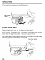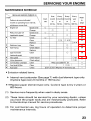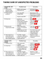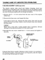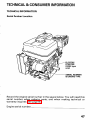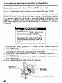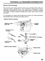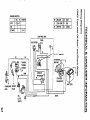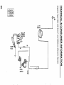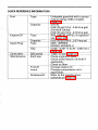
1
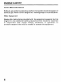
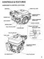
Click SAVE to save this manual to your computer. Thank you for choosing Honda.
The engine exhaust from this product
contains chemicals knownto the State
of California to cause cancer, birth
defects or other reproductive harm.
Keep this owner's manual handy, so you can refer to it a t any time.
This owner's manualis considered a permanent part of the engine and
should remain with the engine if resold.
The information and specifications included in this publication were in
effect a t the timeof approval for printing. Illustrations
are based on the
GX160. Only the QXE2 type is equipped for both electric and manual
starting.HondaMotor
Co., Ltd. reservestheright,however,to
discontinue or change specifications or design
a t any time without
notice and without incurring any obligation whatever. No part of this
publication may be reproduced without written permission.
Congratulations on your selection of a Honda engine. We are certain
you will be pleased with your purchase of one of the finest engines on
the market.
We want to help you get the
best results from your new engine and to
operate it safely. This manual contains the information on how to do
that; please read it carefully.
As ou read this manual, you will find information preceded by a
symbol.Thatinformationisintendedtohelpyouavoid
damage to yourengine, other property, or the environment.
We suggest you read thewarrantypolicytofullyunderstandits
coverage and your responsibilities of ownership. The warranty policy
is a separate document that should have been given to you by your
dealer.
When your engine needs scheduled maintenance, keep in mind that
your Honda servicing dealer is specially trained
in servicing Honda
engines. Your Honda servicing dealer is dedicated to yoursatisfaction
and will bepleased to answer your questionsand concerns.
Best Wishes,
Honda Motor Co., Ltd.
1
INTRODUCTION
A FEW WORDS ABOUT SAFETY
Your safety and the safety of others
are very important. And using this
engine safely is an important responsibility.
To help you make informed decisions aboutsafety, we have provided
operatingproceduresandotherinformationonlabelsandinthis
manual. This information alerts you to potential
hazards that could
hurt you or others.
Ofcourse, it is not practical or possible
to warn you about
all the
hazards associatedwith operating or maintainingan engine. You must
use your own good judgment.
You will findimportant
including:
safety informationin
a varietyofforms,
Safety Labels - on the engine.
A and one
Safety Messages - preceded by a safety alert symbol
of three signal words,DANGER, WARNING, or CAUTION.
These signal words mean:
You WILL be KILLED or SERIOUSLYHURT if
you don't follow instructions.
YouCANbe
KILLED or SERIOUSLY HURT if
you don't follow instructions.
You
CAN
be
HURT
if
you
don't
follow
instructions.
Safety Headings - such as IMPORTANTSAFENINFORMATION.
Safety Section - such as ENGINE SAFEN.
Instructions - how touse this engine correctly andsafely.
This entire book is filled with important safety information
read it carefully.
2
- please
ENGINE SAFETY ........................................................................................
IMPORTANT SAFETY INFORMATION .................................................
5
5
CONTROLS & FEATURES .........................................................................
COMPONENT & CONTROL LOCATIONS .............................................
CONTROLS .............................................................................................
Fuel Valve Lever .................................................................................
Engine Switch .....................................................................................
Choke Lever ......................................................................................
Throttle Lever ...................................................................................
Recoil Starter Grip............................................................................
FEATURES ............................................................................................
Oil A l e e System (applicable engine types)..................................
Circuit Breaker (QXE2 type only) ....................................................
7
7
8
8
9
10
11
11
12
12
12
BEFORE OPERATION ..............................................................................
IS YOUR ENGINE READY TO GO? ......................................................
Check the General Condition of the Engine ...................................
Check the Engine ..............................................................................
Check the Equipment Poweredby This Engine .............................
13
13
13
14
14
OPERATION .............................................................................................
SAFE OPERATING PRECAUTIONS ....................................................
STARTING THE ENGINE .....................................................................
STOPPING THE ENGINE .....................................................................
SETTING ENGINE SPEED ....................................................................
15
15
15
19
20
SERVICING YOUR ENGINE .....................................................................
21
THE IMPORTANCE OF MAINTENANCE .............................................
21
22
MAINTENANCE SAFETY .....................................................................
MAINTENANCE SCHEDULE ...............................................................
23
REFUELING ...........................................................................................
24
FUEL RECOMMENDATIONS ..............................................................
25
ENGINE OIL LEVEL CHECK .................................................................
26
ENGINE OIL CHANGE ..........................................................................
27
ENGINE OIL RECOMMENDATIONS ...................................................
28
TRANSMISSION OIL LEVEL CHECK(applicab1emodels) ................. 29
TRANSMISSION OIL CHANGE(1/2 reduction type) ..........................
30
AIR FILTER INSPECTION .....................................................................
31
AIR CLEANER SERVICE .......................................................................
32
32
Dual-Filter-Element Types ...............................................................
Oil-Bath Type .................................................................................... 34
3
CONTENTS
SERVICING YOUR ENGINE (continued)
SEDIMENT CUP CLEANING ................................................................
SPARK PLUG SERVICE ........................................................................
IDLE SPEED ADJUSTMENT ................................................................
SPARK ARRESTER MAINTENANCE (optional part) .........................
35
36
37
38
HELPFUL TIPS& SUGGESTIONS ..........................................................
STORING YOUR ENGINE ....................................................................
Storage Preparation .........................................................................
Storage Precautions .........................................................................
Removal From Storage....................................................................
TRANSPORTING ..................................................................................
39
39
39
42
43
44
TAKING CARE OF UNEXPECTED PROBLEMS ......................................
ENGINE WILL NOTSTART ..................................................................
ENGINE LACKS POWER ......................................................................
FUSE REPLACEMENT(QXE2 type only)............................................
45
45
45
46
TECHNICAL & CONSUMER INFORMATION .........................................
47
TECHNICAL INFORMATION ................................................................
47
Serial Number Location ................................................................... 47
Battery connections forElectric Starter (QXE2 type only)............48
Remote Control Linkage ..................................................................
49
Carburetor Modification for High Altitude.....................................
50
Oxygenated Fuels ............................................................................
51
Emission Control System Information...........................................
52
Air Index ............................................................................................ 54
Specifications ................................................................................... 55
Wiring Diagrams ..............................................................................
57
CONSUMER INFORMATION ...............................................................
59
Honda Publications ..........................................................................
59
Warranty Service Information.........................................................
60
QUICK REFERENCE INFORMATION .............................
4
Inside back cover
IMPORTANT SAFETY INFORMATION
Most accidents with engines can beprevented
if youfollow all
instructionsinthismanualandontheengine.Someofthemost
common hazardsarediscussedbelow,
along with the best way to
protect yourself and others.
Owner Responsibilities
Honda engines are designed to give safe and dependable service if
operated according to instructions. Read and understand this
owner’s manual before operating the engine. Failure to do so could
result in personal injury or equipment damage.
Know how to stop the engine
quickly, and understand the operation
of all controls. Never permit anyone to operate the engine without
proper instructions.
Do not allow children tooperate the engine. Keep children and pets
away from thearea of operation.
Refuel With Care
Gasolineisextremelyflammable,andgasolinevaporcanexplode.
Refuel outdoors, in a well-ventilated area, with the engine stopped.
Never smoke near gasoline, and keep other flames and sparks away.
Always store gasoline in an approved container. If any fuel is spilled,
make sure thearea is dry before starting the engine.
Hot Exhaust
The muffler becomes very hot during operation and remains hot for
a while after stopping the engine.Be careful not to touch the muffler
while it is hot. Letthe engine cool before storing
it indoors.
Topreventfire
hazards and to provide adequateventilationfor
stationary equipment applications, keep the engine at least 3 feet (1
meter)awayfrombuildingwallsandotherequipmentduring
operation. Do not place flammable objects close to the engine.
5
ENGINE SAFETY
Carbon Monoxide Hazard
Exhaust gas contains poisonous carbon monoxide. Avoid inhalation
of
exhaust gas. Never run the engine ainclosed garage or confinedarea.
Other Equipment
Review the instructions provided with the equipment powered by this
engine for any additional safety precautions that should be observed
inconjunctionwithenginestartup,shutdown,oroperation,or
protective apparel that maybe neededto operate the equipment.
CONTROLS & FEATURES
COMPONENT & CONTROL LOCATIONS
MUFFLER\
THROlTLE LEVER
ENGINE SWITCH
(QXES type)
CIRCUIT BREAKER
(QXE2 type)
AIR CLEANER
RECOIL STARTER
CHOKE LEVER
FUEL VALVE LEVER
'
I
[Inner vent type]
BREATHER TUBE
STARTER GRIP
FUEL TANK
ELECTRIC STARTER
OIL DRAIN PLUG'
'
FUEL FILLER CAP
7
CONTROLS & FEATURES
CONTROLS
Fuel Valve Lever
The fuel valve opens and closes the
and the carburetor.
passage between the fuel tank
The fuel valve lever must in
bethe ON position for the engine to run.
When the engine is not in use, leave the fuel valve lever in the OFF
position to prevent carburetor flooding and to reduce the possibility
of
fuel leakage.
FUEL
VALVE
LEVER
8
CONTROLS & FEATURES
~~
Engine Switch
The engine switchenables and disables the ignition system.
The engine switch must be in the
ON position for the engine to run.
OFF position stops the engine.
Turning the engine switch to the
ALL ENGINES EXCEPT
QXE2
QXE2
TYPE
ENGINE SWITCH
CIRCUIT BREAKER
QXE2 Type
The engine switch on the QXE2 type includes a START position for
operating the electric starter. The key automatically returns to the ON
position whenreleased from theSTART position.
The circuit breaker, whichislocatedbelowthe
battery charging circuit(see page 12).
key, protectsthe
9
CONTROLS & FEATURES
Choke Lever
The choke lever opens and closes the choke valve
in the carburetor.
The CLOSED position enriches the fuel mixture for starting a cold
engine.
The OPEN position provides the correct fuel mixture for operation
after starting, andfor restarting a warm engine.
Someengineapplicationsuse
a remotely-mountedchokecontrol
rather than the engine-mounted choke lever shown
here.
CHOKE LEVER
1
10
CONTROLS & FEATURES
Throttle Lever
The throttle lever controls engine
speed.
Moving the throttle lever in the directions shown
run faster or slower.
makes the engine
Someengineapplicationsuse
a remotely-mountedthrottlecontrol
rather than the engine-mounted throttle lever shown
here.
THROTTLE LEVER
/
Recoil Starter Grip
Pulling the starter grip operates the recoil starter to crank the engin
STARTER GRIP
11
CONTROLS & FEATURES
FEATURES
Oil Alert@ System
(applicable engine types)
The Oil Ale@ system is designed to prevent engine damage caused
by an insufficient amount of oil in the
crankcase. Before the oil level in
the crankcase can fall below a safe limit, the Oil Ale@ system
will
automatically stop the engine (the engine switch
will remain in theON
position).
If the engine stops andwill not restart, check the engine oil level (page
26 ) before troubleshooting in other areas.
Circuit Breaker (QXEZ type only)
The
circuit
breaker
protects
the
battery
charging
circuit.
A short
circuit, or a battery connected with
reverse polarity, will trip the circuit
breaker.
The
green
indicator
inside
the
circuit breaker will pop out to show
that the circuitbreaker has switched
off.Ifthis
occurs, determinethe
cause of the problem, and correct it
before resetting the circuit
breaker.
CIRCUIT
BREAKER
Push thecircuit
reset.
12
breaker button to
IS YOUR ENGINE READY TO GO?
For your safety, and to maximize the service life of your equipment,
it
isveryimportantto
take a fewmomentsbeforeyouoperatethe
engine to check its condition. Be sure to take care of any problem you
find, or have your servicing dealer correct it, before you operate the
engine.
I
Improperly maintaining this
engine,
or failing to
correct a problem
before operation, could causea
malfunction in which you could be
seriously injured.
i
Always performa preoperation
inspection before each operation,
and correct any problem.
Before beginning your preoperation
checks, be sure the engine is level
and the engine switch is in OFF
the position.
Check the General Conditionof the Engine
0
Look around and underneaththe engine for signs of oil or gasoline
leaks.
Remove any excessive dirt or debris, especially around the muffler
and recoil starter.
Look for signs of damage.
Check that all shields and covers are in place, and all nuts, bolts, and
screws are tightened.
13
Check the Engine
Check the engine oil level (see page 26). Running the engine with a
low oil levelcan cause engine damage.
The Oil Alert? system (applicable engine types) will automatically
stop the engine before the oil level falls below
safe limits. However,
toavoidtheinconvenienceofanunexpectedshutdown,always
check the engine oil level before startup.
Check the transmission oil level on applicable engine types
(see
page 29 ). Oil is essentialto transmission operation and long life.
Check the air filter(see page 31 ). A dirty air filterwill restrict airflow
to thecarburetor, reducing engine performance.
Check the fuel level (see page 24 ). Starting with a full tank will help
to eliminate or reduce operating interruptions for refueling.
Check the Equipment Poweredby This Engine
Review the instructions provided with the equipment poweredby this
engine for any precautions and procedures that should be followed
before engine startup.
14
OPERATION
SAFE OPERATING PRECAUTIONS
Before operating the engine for the first time, please review the
IMPORTANT SAFETY INFORMATIONon page 5 and the chapter titled
BEFORE OPERATION.
Carbon monoxide gas is toxic.
Breathing it can cause
unconsciousness and even kill you.
Avoid any areas or actionsthat
expose you to carbon monoxide.
Review the instructions provided with the equipment powered by this
engineforanysafetyprecautionsthatshouldbeobserved
in
conjunction with engine startup, shutdown, or operation.
STARTING THE ENGINE
1. Move the fuel valve lever to ON
the position.
FUEL VALVE
LEVER
15
OPERATION
2. To start a cold engine, move thechoke lever to theCLOSED position.
To restart awarm engine, leave the choke leverin theOPEN position.
Some engine applications usea remotely-mounted choke control
rather than the engine-mounted choke lever shown
here.
CHOKE LEVER
I \\
3. Move the throttlelever away from the SLOW position, about 1/3 of
the way toward the
FAST position.
.
Some engine applications use a remotely-mounted throttle control
rather than the engine-mounted throttle lever shown
here.
T H R O l T L E LEVER
16
OPERATION
4. Turn the engine switch to ON
the position.
ALL ENGINES EXCEPTQXE2
QXE2
TYPE
ENGINE SWITCH
5. Operate the starter.
RECOIL STARTER (all engine types):
Pull the starter grip lightly until you
feel resistance, then pull briskly.
Return the starter grip gently.
STARTER GRIP
17
OPERATION
ELECTRIC STARTER (QXE2 type):
Turn the key to the START position,
and holdit there until the enginestarts.
If theenginefailstostartwithin
5
seconds, release the key, and wait at
least 10 seconds before operating the
starter again.
piEq
Usingtheelectricstarterformore
than 5 seconds at a time will
overheat
the starter motor
and can damage it.
Whentheengine
starts,release
key, allowing it to
return
to
the
position.
the
ON
ENGINE SWITCH
(QXE2 type)
6. If the choke lever has been moved to the CLOSED position to start
the engine, gradually move it to the OPEN position as the engine
warms up.
CHOKE LEVER
18
OPERATION
STOPPING THE ENGINE
To stop the engine in an emergency, simply turn the engine switch to
the OFF position.
Under
normal
conditions,
use
the
following
procedure.
1. Move the throttle
lever to theSLOW position.
Some engine applications use a remotely-mounted throttle control
rather than the engine-mounted throttle lever shown
here.
THROlTLE LEVER
2. Turn the engine switch to OFF
the position.
ALL ENGINES EXCEPT
QXEZ
QXEZ
TYPE
ENGINE SWITCH
19
OPERATION
3. Turn the fuel valve lever to OFF
the position.
FUEL VALVE
LEVER
SETTING ENGINESPEED
Position the throttle lever for the desired engine
speed.
Someengineapplicationsusearemotely-mountedthrottlecontrol
rather than the engine-mounted throttle lever shown
here.
For engine speed recommendations, refer to the instructions provided
with the equipment powered by this engine.
THROTTLE LEVER
20
SERVICING YOUR ENGINE
THE IMPORTANCE OF MAINTENANCE
Good maintenance is essential for safe, economical, and trouble-free
operation. It will also help reduceair pollution.
Improperly maintaining thisengine,
a problem
or failure to correct
before operation, can cause a
malfunction in which you
can be
seriously hurt orkilled.
Always follow the inspection and
maintenance recommendations and
schedules in thisowner's manual.
To help you properlycare for yourengine, the followingpages include
a maintenance schedule, routine inspection
procedures, and simple
maintenance procedures using basic hand tools. Other service tasks
that are more difficult, or require special tools, are best handled by
professionals and are normally performed by a Honda technician or
other qualified mechanic.
The maintenance schedule applies to normal operating conditions. If
you operate your engine under unusual conditions, suchas sustained
high-load or high-temperature operation, or
use in unusually wet or
dusty conditions, consult your servicing dealer for recommendations
applicable to your individualneeds and use.
Maintenance, replacement or repair of emission control devices and
systems maybedoneby
any
engine
repair establishment or
individual, using parts that are "certified" to EPA standards.
21
SERVICING YOUR ENGINE
MAINTENANCE SAFETY
Some of the most important safety precautions follow. However, we
cannotwarnyouofeveryconceivable
hazard thatcan
arise in
performing maintenance. Only you can decide whether or not you
should performa giventask.
Failure to properly follow
maintenance instructions and
precautions cancause you to be
seriously hurt orkilled.
Always follow the procedures and
precautions in the owner’s manual.
Safety Precautions
Make sure the engine is off before you begin any maintenance or
repairs. This will eliminate several potential hazards:
-Carbon monoxide poisoning from engine exhaust.
Be sure there is adequate ventilation whenever you operate the
engine.
-Burns from hotparts.
Let the engine and exhaust system cool before touching.
-Injury from moving parts.
Do not run the engine
unless instructedto doso.
Read the instructions before youbegin, and make sure you have the
tools andskills required.
Toreduce thepossibilityoffireorexplosion,becarefulwhen
workingaroundgasoline.
Use only anonflammablesolvent,not
gasoline, to clean parts. Keep cigarettes, sparks and flames away
from all fuel-related parts.
Remember that your servicing dealer knows your engine best and is
fully equipped to maintain and
repair it.
Toensurethebestqualityandreliability,useonlynew,genuine
Honda parts or their equivalents for repair and replacement.
22
SERVICING YOUR ENGINE
MAINTENANCE SCHEDULE
Emission-related items.
*
Internal vent carburetor(See page7 ) with dual element type only.
(Cyclone type every6 months or 150 hours.)
* * Replace paper element type only. Cyclone type every
2 years or
600 hours.
(1) Service more frequently when usedin dusty areas.
(2) These items should be serviced by your servicing
dealer, unless
you have the proper tools and are mechanically proficient. Refer
to Honda shop manual for
service procedures.
(3) For commercial use, log hours of operation to determine proper
maintenance intervals.
23
SERVICING YOUR ENGINE
REFUELING
Fuel tank capacities
GX120: 0.66 US gal (2.5 Q ,0.55 Imp gal)
GX160: 0.95 US gal (3.6Q ,0.79 Imp gal)
GX200: 0.95 US gal (3.6 Q , 0.79 Imp gal)
With the engine stopped, remove the fuel tank cap and
check the fuel
level. Refill the tankif the fuel levelis low.
Gasoline is highlyflammable and
explosive.
You can be burned or seriously
injured when handling fuel.
Stop the engine andkeep heat,
sparks, and flame away.
Handle fuel onlyoutdoors.
Wipe up spills immediately.
24
SERVICING YOUR ENGINE
Refuel in a well-ventilated area before starting the engine. If the engine
has been running, allowit to cool. Refuel carefully to avoid spilling fuel.
Do not fill above the fuel strainer shoulder. After refueling, tighten the
fuel tank cap securely.
Never refuel the engine inside a building where gasoline fumes may
reach flames orsparks. Keep gasoline away from appliance pilot lights,
barbecues, electric appliances, power tools, etc.
Spilled fuel is not onlya fire hazard, it causes environmental damage.
Wipe up spills immediately.
m
Fuel can damage paint and plastic. Be careful not to spill fuel when
filling your fuel tank. Damage caused by spilled fuel is not covered
under warranty.
FUEL RECOMMENDATIONS
Use unleaded gasoline with a pumpoctane rating of 86 or higher.
These engines are certified to operate on unleaded gasoline. Unleaded
gasoline produces fewer engine and spark plug deposits and extends
exhaust system life.
Never use stale or contaminated gasoline or an oil/gasoline mixture.
Avoid getting dirt or water in the fuel tank.
Occasionally youmay
heara
light "spark knock" or"pinging"
(metallic rapping noise) while operating underheavy loads. This is no
cause for concern.
Ifsparkknock
or pinging occurs a t asteadyengine
speed, under
normal load, changebrands of gasoline.Ifsparkknock
or pinging
persists, see an authorized Honda servicing dealer.
Running the engine with persistent spark knock or pinging can cause
engine damage.
Running the engine with persistent spark knock or pinging is misuse,
and the Distributor's Limited Warrantydoes not cover parts damaged
by misuse.
SERVICING YOUR ENGINE
~~~
ENGINE OIL LEVEL CHECK
Check theengineoillevelwiththeenginestoppedandinalevel
position.
1. Remove the filler cap/dipstick and wipe
it clean.
2. Insert and remove the dipstick with out screwing it into the filler
neck. Check the oil level shown on the dipstick.
3. If the oil level is low, fill to the edge of the oil filler hole with the
recommended oil(see page 28).
4. Screw in the filler cap/dipstick
securely.
'FILLER CAP/DIPSTICK
[NOTICE
I
LOWER LIMIT
Running the engine with a low oillevel can causeengine damage.
The Oil Alert@system (applicable engine types)will automatically stop
the engine before the oil level falls below
safe limit. However, to avoid
theinconvenienceofanunexpectedshutdown,always
check the
engine oil level before startup.
26
SERVICING YOUR ENGINE
ENGINE OIL CHANGE
Drain the used oil while the engine is warm. Warm oil drains quickly
and completely.
1. Place a suitable container below the engine to catch the used oil,
then remove the filler cap/dipstick
and the drain plug.
2.Allow the used oil to drain completely, then reinstall the drain plug,
and tightenit securely.
Please dispose of used motor oil ainmanner that is compatible with
the environment. We suggest youtake used oil in a sealed container
to your local recycling center or service station for reclamation. Do
not throwit in thetrash, pour it on the ground, or down
a drain.
3. With the engine in a level position, fill to the outer edge of the oil
filler holewith the recommended oil(see page28).
Engine oil capacity: 0.63 US qt (0.60 0 ,0.53 Imp qt)
m
Running the engine with a low oillevel can causeengine damage.
The Oil Alert@ system (applicable engine types)
will automatically
stoptheenginebeforetheoillevelfallsbelowthe
safe limit.
However, to avoid the inconvenience of an unexpected shutdown,
fill to the upper limit, and
check the oil level regularly.
4. Screw in the filler cap/dipstick
securely.
FILLER CAP/
f
DRAIN BOLT
OIL LEVEL-
27
SERVICING YOUR ENGINE
ENGINE OIL RECOMMENDATIONS
Oil is a major factor affecting performance and service life. Use
4-stroke automotive detergent oil.
SAE IOW-30 is recommended for generaluse. Other viscosities shown
in the chart may be used when the average temperature area
in your
is
within the recommendedrange.
I
-30
I
I
I
1
I
I
-20
-10
0
10
20
30
I
40'C
AMBIENT TEMPERATURE
The SAE oil viscosity and service classification are in the API label on
theoilcontainer.Hondarecommendsthatyouuse
API SERVICE
category SJ oil.
28
SERVICING YOUR ENGINE
TRANSMISSION OIL LEVEL CHECK
(applicable engine types)
Check the transmission oil levelwith the engine stopped and in a level
position.
1/2 Reduction Transmission With CentrifugalClutch
1. Remove the filler cap/dipstick and wipe
it clean.
2. Insert and removethe dipstick without screwing
it into the filler
hole.
Check the oil level shown on thedipstick.
3. If the oil level is low, add oil to reach the upper limit mark on the
dipstick. Use the same oil that is recommended for the engine (see
page 28).
4. Screw in the filler cap/dipstick
securely.
.
.
ILLER CAP/DIPSTICK
UPP
LlMI
f
1/6 Reduction Transmission
DRAIN BOLT
1. Remove the oil-level-check bolt, and
see weather the oil level is
edge of the bolt hole.
at the
2. If the oil level is below the
check
bolt hole, remove the filler bolt, and
add oil until1 it starts to flow out the
check bolt hole. Use the same oil
that is recommended for the engine
(see page 28).
3. Installtheoil-level-checkboltand
filler bolt. Tighten them
securely.
I
OIL-LEVEL-CHECK
BOLT
29
SERVICING YOUR ENGINE
TRANSMISSION OIL CHANGE
(1/2 reduction transmission with centrifugal clutch)
Drain the used oil while the engine is warm. Warm oil drains quickly
and completely.
1. Please a suitable container below the transmission to catch the used
oil, then remove the filler capddipstick and the drain plug.
2.Allow the used oil to draincompletely, then reinstall the drain plug,
and tighten it securely.
Please dispose of used motor oil
in a manner that is compatible with
the environment. We suggestyou take Lased oil in a sealed container
Do
to your local recyling center or service station for reclamation.
not throwit in the trash, pour it on the ground, or down a drain.
3. With the enginein a level position, fill to the upperlimit mark on the
dipstick with the same oil that is recommended for the engine (see
page 28). To check the oillevel, insert and move the dipstick without
screwing it into the filler
hole.
Transmission oil capacity: 0.53 US qt (U.50 !2,0.44 Imp qt)
I NOTICE I
Running the engine with a low transmission oil level cancause
transmission damage.
4. Screw in the filler cap/dipstick securely.
FILLER CAPIDIPSTICK
U
LI
LOWER LIMIT
30
DRAIN BOLT
’
SERVICING YOUR ENGINE
AIR FILTER INSPECTION
Remove the air cleaner cover and inspect the filter. Clean or replace
dirtyfilterelements.Always
replace damagedfilterelements.If
equipped with an oil-bath air cleaner, also check the oil level.
Refer to pages 32-34 for instructions that apply to the aircleaner and
filter on your type engine.
of
PAPER
FILTER
ELEMENT
FOAM
FILTER
ELEMENT
STANDERD
FILTER-ELEMENT
DUAL-FILTERELEMENT TYPE
(see p. 32-33)
CYCLONE DUAL-
OIL-BATH TYPE
(seep. 34)
TYPE
(seep. 32-33)
31
SERVICING YOUR ENGINE
AIR CLEANER SERVICE
A dirty air filter will restrict air flow to thecarburetor, reducing engine
performance. If you operate the engine in very dusty areas, clean the
air filter more often than specified inMAINTENANCE
the
SCHEDULE.
Operating the enginewithout an air filter, or with adamaged air filter,
will allow dirt enter
to the engine, causing rapid enginewear. This type
of damage is not covered by the Distributor’s Limited Warranty.
Dual-Filter-Element Types
1. Remove the wing nut from the
aircleanercover,andremove
the cover.
STANDERD DUAL-FILTER-ELEMENT
TYPE
2. Remove the wing nut from the
air filter, and remove the filter.
3. Remove the foam filter from the
paper filter.
4. Inspect both air filter elements,
andreplace
themifthey
are
damaged.Alwaysreplacethe
paper air filter element
at the
scheduled interval (see page
23).
5. Clean the air filter elements if
they are to bereused.
32
ELEMENT
SERVICING YOUR ENGINE
Paper airfilterelement:Tapthe
filter
element
several
times
on
a
hard surface to remove dirt, or blow
compressed
[not
exceeding
air
30
psi (207 kPa, 2.1 kgf / cm’)] through
the filter element from the inside.
Never try to brush off dirt; brushing
will force dirt into thefibers.
CYCLONE DUAL-FILTER-ELEMENT
TYPE
SPECIAL PAN SCREW (3)
PRECLEANER CAP
Foam airfilterelement:
Clean in
warm soapy water, rinse, and allow
todrythoroughly.Orcleanin
A,RG
nonflammable solvent and allow to
dry. Dip the filter element in
clean
engine oil, then squeeze outall
excess oil. The engine will smoke
when started if too much oil is left
in
the foam.
6. CYCLONE TYPE ONLY: Remove the three pan-head screws from the
precleaner cap, then remove the cyclone housing and air guide.
Wash the parts with water, dry them thoroughly, and reassemble
them.
Be sure to install the air guide
as shown in the illustration.
Install the cyclone housingso the air intake tab fits into the groove in
the precleanercap.
1
7. Wipe dirt from the inside of the air cleaner base and cover, using a
moist rag. Be careful to prevent dirt from entering the air duct that
leads to the carburetor.
8. Place thefoam airfilterelementoverthepaper
element, and
reinstalltheassembledairfilter.
Be surethe gasket is in place
beneath the air filter. Tighten the air filter wing nut securely.
9. Install the aircleaner cover, and tighten the cover wing nut
securely.
33
SERVICING YOUR ENGINE
Oil-Bath Type
1. Remove the wingnut, and remove the air cleaner cap and cover.
2. Remove the air filter from the cover, Wash the cover and filter in
warm, soapy water, rinse, and allow to dry thoroughly. Or clean in
nonflammable solvent and allow to dry.
3. Dip the filterin clean engine oil, then squeeze out all excess oil. The
engine will smoke if too much oil
is left in the foam.
4. Emptytheusedoilfromthe
air cleaner case, washoutany
accumulated dirt with nonflammable solvent, and dry thecase.
5. Fill the air cleaner case to theOIL LEVEL mark with the same oil that
is recommended for the engine
(see page28).
Oil capacity: 2.0 US oz (60 cm3, 2.1 Imp 02)
6. Reassemble the aircleaner, and tighten the wing nut
securely.
/WING
NUT
OIL LEVEL
34
SERVICING YOUR ENGINE
SEDIMENT CUPCLEANING
1. Move the fuel valve to the
sediment cup and O-ring.
OFF Dosition. then remove the fuel
Gasoline is highly flammable and
explosive.
You can be burned or seriously
injured when handling fuel.
Keep heat, sparks and flame away.
Handle fuel only outdoors.
Wipe up spills immediately.
2. Wash the sediment cup and O-ring in nonflammable solvent, and
dry them thoroughly.
3. Place the O-ring in the fuel valve, and install the sediment
Tighten the sediment cup
securely.
cup.
4. Move the fuel valve to the
ON position, and check for 1eaks.Replace
the O-ring if there is any
leakage.
O-RING
35
SERVICING YOUR ENGINE
SPARK PLUG SERVICE
Recommended spark plugs:
BPR6ES (NGK)
W20EPR-U (DENSO)
p G q
An incorrect spark plug can causeengine damage.
1. Disconnect the spark plug cap, and remove any dirt from around the
spark plug area.
2. Remove the spark plug
with a 13/16-inch sparkplug wrench.
SPARK PLUG WRENCH
3. Inspect the spark
plug.
Replace it
the
if
electrodes
are
worn,
or if the
insulatoris
cracked orchipped.
Clean the spark plug with a wire
brush if you
are going toreuse it.
4. Measure the spark plug electrode
gap with asuitablegauge.The
g a p s h o u l d b e 0.028-0.031 i n
(0.70-0.80 mm). Correct the gap,
if necessary, by carefully bending
the side electrode.
5. Install the spark plug carefully, by
hand, to avoid cross-threading.
36
0.028-0.031 in
(0.70-0.80 mm)
SERVICING YOUR ENGINE
6,Afterthesparkplug
seats, tightenwith
wrench to compress the water.
a 13/16-inchsparkplug
If reinstalling the used spark plug, tighten 1/8-1/4 turn after the
spark plug seat.
if installing a new spark plug, tighten
seats.
1/2 turn after the spark plug
I NOTICE I
A loose sparkplug can overheatand damage the engine.
Overtightening the spark plug can damage the threads in the
cylinder head.
7. Attach the spark plug
cap.
IDLE SPEED ADJUSTMENT
1. Start the engine outdoors, and allow
temperature.
it to warm up to operating
2. Move the throttle lever its
to slowest position.
3. Turn the throttle stop screw to obtain the standerdspeed.
idle
Standerd idle speed:1,400%~rpm
THROlTLE STOP SCREW
/
37
SERVICING YOUR ENGINE
SPARK ARRESTER SERVICE (optional equipment)
Your engine is not factory-equipped with a spark arrester.
In some
areas, it is illegal tooperate an engine without a spark arrester. Check
local
laws
and
regulations.
A
spark
arrester
is
available
from
authorized Honda servicing dealers.
Thesparkarrester
mustbe
functioning as designed.
servicedevery
100 hoursto
keep it
If the engine has been running, the mufflerwill be very hot. Allow the
muffler to cool before servicing the spark
arrester.
1. Remove the three
4 m m screws from the exhust deflector, and
remove the deflector.
2. Removethefour
5 mm screws from the muffler protector and
remove the muffler protector.
3. Remove the 4 mm screw from the spark arrester, and remove the
spark arrester from the muffler.
7
-
5 mm SCREWS
MUFFLER
PROTECTOR
EXHAUST
DEFLECTOR
SPARK
ARRESTER
4. Usea brush to remove carbon deposits
from the spark arrester screen. Be careful
to avoid damaging the
screen.
SCREEN
The spark arrester must be free of breaks
and holes. Replace the spark arrester if it is
damaged.
5. Install the sparkarrester, muffler protector, and exhaust deflector in
the reverse order of disassembly.
38
HELPFUL TIPS& SUGGESTIONS
STORING YOUR ENGINE
Storage Preparation
Properstoragepreparationisessential
for keeping yourengine
troublefree and looking good. The following steps will help to keep
rustandcorrosionfromimpairingyour
engine’s functionand
appearance, and will make the engine easier to start when you use it
again.
Cleaning
If the enginehas been running, allowit to cool forat least half an hour
before cleaning. Clean all exterior surfaces, touch up any damaged
paint, and coat otherareas that may rust with a light film of oil.
Using a garden hose or pressure washing equipment can force
water into the air cleaner or muffleropening. Water in the air cleaner
will soak the air filter, and water that passes through the air filter or
muffler can enterthe cylinder, causing damage.
Water contacting a hot engine can cause damage. If the engine has
been running, allow it to cool for at least half an hour before
washing.
Fuel
Gasoline will oxidizeanddeteriorate
in storage.Oldgasoline
will
cause hard starting, and it leaves gum depositsthatclogthefuel
system. If the gasoline in your engine deteriorates during
storage, you
may need to have the carburetor and other fuel system components
serviced or replaced.
4
The lengthoftimethatgasolinecanbeleft
in yourfueltankand
carburetor without causing functional problems
will vary with such
factors as gasoline blend, your storage temperatures, and whether the
fuel tank is partially or completely filled. Theinair
a partially filled fuel
tankpromotesfueldeterioration.Verywarmstorage/temperatures
accelerate fuel deterioration. Fuel deterioration problems may occur
within a few months, or even less if the gasoline was not fresh when
you filled the fuel
tank.
HELPFUL TIPS& SUGGESTIONS
The Distributor’s Limited Warranty does notcoverfuelsystem
damage or engine performance problems resulting from neglected
storage preparation.
a fuelstabilizerthatis
Youcan extend fuel storage life by adding
formulatedforthatpurpose,oryou
can avoidfueldeterioration
carburetor.
problems
and
draining
tank
fuel
by
the
ADDING A FUEL STABILIZERTO EXTEND FUEL STORAGE LIFE
When adding a fuel stabilizer, fill the fuel tank with fresh gasoline. If
onlypartiallyfilled,airinthe
tank willpromotefueldeterioration
during storage. If you keep a container of gasoline for refueling, be
sure that it contains only fresh gasoline.
1. Add fuel stabilizer following the manufacturer’s instructions.
2. After adding a fuel stabilizer, run the engine outdoors for
10 minutes
to be sure that treated gasolinehas replaced the untreated gasoline
in the carburetor.
3. Stop theengine, and move the fuel valve to OFF
the position.
FUEL VALVE
40
,
HELPFUL TIPS& SUGGESTIONS
DRAINING THEFUEL TANK AND CARBURETOR
1. Place an approved gasoline container below the carburetor, and
use
a funnel to avoid spilling fuel.
2. Remove the carburetor drain bolt and sedimentcup, then move the
fuel valve lever to the
ON position.
Gasoline is highly flammable and
explosive.
You can be burned or seriously
injured when handling fuel.
Keep heat, sparks and flame away.
Handle fuel only outdoors.
Wipe up spills immediately.
SEDIMENT
CUP
3. After all the fuel has drain into the container, reinstall the drain bolt
and sediment cup. Tighten them securely.
41
HELPFUL TIPS& SUGGESTIONS
Engine Oil
1. Change the engine oil(see page27).
2. Remove thespark plugs (see page36).
3. Pour a tablespoon(5- 10 cc) of clean engine oil into the cylinder.
4. Pull the starter rope several times
to distribute the oil in the cylinder.
5. Reinstall the spark plugs.
6. Pull the starter rope slowly until1 resistance is felt and the notch on
the starter pulley aligns with the hole a t the top of the recoilstarter
cover. This will close the valves so moisture cannot enter the engine
cylinder. Return the starter rope gently.
Align notch on pulley
with hole at top of cover.
Storage Precautions
If yourenginewillbestoredwithgasoline
in thefueltankand
carburetor, it is important to
reduce the hazard of gasolinevapor
ignition. Select a well-ventilated storagearea away from any appliance
that operates with a flame, such as a furnace, water heater, or clothes
dryer. Also avoid any area with a spark-producing electric motor, or
where power toolsare operated.
Ifpossible,avoidstorage
areas withhighhumidity,
promotes rust and corrosion.
because that
Unless all fuel has been drained from thetank,
fuelleave the fuel valve
lever in the OFF position toreduce the possibility of fuel
leakage.
42
HELPFUL TIPS& SUGGESTIONS
Position the equipment so the engine islevel. Tilting can cause fuel or
oil leakage.
=
.
With the engine and exhaust system
cool, cover the engine to
keep out
dust. A hotengineandexhaustsystem
can igniteormeltsome
materials. Do not use sheet plasticas a dust cover.A nonporous cover
will trap moisture around the engine, promoting rust and corrosion.
If equipped with a battery for an electric starter (QXE2 type), recharge
the battery once a month while the engine is in storage.
This will help to extend the service life of the battery.
Removal From Storage
Check your engine as described in theBEFORE OPERATIONchapter of
this manual.
If the fuel was drained during storage preparation, fill the tank
with
fresh gasoline. If you keep a container of gasoline for refueling, be
surethat
it containsonlyfreshgasoline.Gasolineoxidizesand
deteriorates over time, causing hard starting.
If the cylinders were coated with oil during storage preparation, the
engine may smoke briefly at startup. This is normal.
43
HELPFUL TIPS& SUGGESTIONS
TRANSPORTING
If the engine has been running, allow it to cool for at least 15 minutes
beforeloadingtheengine-poweredequipmentonthetransport
vehicle. A hot engine and exhaust systemcan burn you andcan ignite
some materials.
Keep the engine level when transporting to reduce the possibility of
fuel leakage. Move the fuel valve lever to the
OFF position.
44
ENGINE WILL NOT
START
1. QXE2 electric
starting: Check
battery andfuse.
2. Check control
positions.
Possible Cause
Battery discharged.
Fuse burnt out.
Recharge battery.
Replace fuse (p. 46).
Fuel valve OFF.
Choke OPEN.
Move leverto ON.
Move lever to
CLOSED
unless engineis warm.
Turn engine switch to
ON.
Refuel (p. 24).
Drain fuel tank and
carburetor (p. 41 1.
Refuel with fresh
gasoline.(p. 24)
Engine switch OFF.
3. Check fuel.
4. Remove and
inspect spark plugs.
5. Take engine to an
authorized Honda
servicing dealer, or
refer to shop manual.
Out of fuel.
Bad fuel; engine
stored without treating
or draininggasoline,
or refueledwith bad
gasoline.
Spark plugs faulty,
fouled, or improperly
gapped.
Spark plugs wet with
fuel (flooded engine).
Fuel filter clogged,
carburetor malfunction,
ignition malfunction,
valves stuck, etc.
c
ENGINE LACKS
POWER
1. Check air filter.
2. Check fuel.
authorized Honda
servicing dealer, or
Correction
Possible Cause
Filter element(s)
clogged.
Bad fuel; engine
stored without treating
or draininggasoline,
or refueled with bad
gasoline.
Fuel filter clogged,
carburetor malfunction,
ignition malfunction,
valves stuck, etc.
Clean, gap, or replace
spark plugs (p.36).
Dry and reinstallspark
plugs. Start engine
with throttle lever
in FAST position.
Replace or repair
faulty componentsas
necessary.
Correction
Clean or replace filter
element(s) (p. 32-34).
Drain fuel tank and
carburetor (p. 411.
Refuel with fresh
gasoline (P. 24).
Replace or repair
faulty componentsas
necessary.
TAKING CARE OF UNEXPECTED PROBLEMS
FUSE REPLACEMENT (QXEZ type only)
Theelectricstarterrelaycircuitandbatterychargingcircuitare
protected by a 5-ampere fuse. Ifthe fuse burns out, the electric starter
will not operate. The engine can be started manuallyif the fuse burns
will not charge the battery.
out, but running the engine
1. Remove the 6 X 12 m m screw from the rear cover of the engine
switch box.
2. Remove the fusecover, and inspect the fuse.
If the fuse is burnt out, remove the fuse
cover, then pull out and
discard the burnt-out fuse. Install a new 5-ampere
fuse, and reinstall
the fuse cover.
Neveruse a fuse with a rating greater than 5 amperes. Serious
damage to the electrical system or a fire couldresult.
3. Reinstall the rear cover. Install the 6 X 12 mm screw and tighten it
securely.
ENGINE SWITCH
REAR COVER
6 X12mm
SPECIAL SCREW
J
Frequent fuse failure usually indicates a short circuit or an overload
in
the electrical system. If the fuse burns out frequently, take the engine
to a servicing Honda dealer for
repair.
46
TECHNICAL & CONSUMER INFORMATION
TECHNICAL INFORMATION
Serial Number Location
Record the engine serial number in the
space below. Youwill need this
serialnumberwhenordering
parts, andwhenmakingtechnicalor
warranty inquires (see page
60 ).
Engine serial number:
47
TECHNICAL & CONSUMER INFORMATION
Battery Connections for Electric Starter (QXE2 type only)
Use a 12-volt batterywith an ampere-hour rating ofa t least 18 Ah.
Be careful not to connect the battery in reverse polarity, as this will
short circuit the battery charging system. Always connect the positive
( + ) battery
cable
to
the
battery
terminal
before
connecting
the
negative ( - ) battery cable, so your tools cannotcause a short circuit if
they touch a grounded part while tightening the positive ( + ) battery
cable end.
1
A battery can explode if you do not
follow the correct procedure,
seriously injuring anyone nearby.
Keep all sparks, open flames, and
smoking materials away from the
battery.
1. Connect thebatterypositive
( + ) cable tothe startersolenoid
terminal as shown.
2. Connect the battery negative (-1 cable t o an engine mounting bolt,
frame bolt, or other good engine ground connection.
3. Connect the battery positive (+) cable to the battery positive ( + )
terminal as shown.
4. Connect the battery negative ( - ) cable to the battery negative ( - )
terminal as shown.
5. Coat the terminals and cable ends
with grease.
NEGATIVE (- 1
BATTERY CABLE
STARTER
SOLENOID
'POSITIVE (+) BATTERY CABLE
48
TECHNICAL & CONSUMER INFORMATION
Remote ControlLinkage
Thethrottleandchokecontrollevers
are providedwithholesfor
optional
cable
attachment.
The
following
illustrations
show
installation examples for a solid wire cable and for a flexible, braided
wire cable. If using a flexible, braided wire cable, add a return spring
as shown.
It is necessary to loosen the throttle lever friction nut when operating
the throttle witha remotely-mounted control.
REMOTE THROTTLE LINKAGE
THROTTLE LEVER
PIVOT NUT
RETURN
SPRING
Flexible wire core
mouTg
-4
W
mounting
REMOTE CHOKE LINKAGE
I
R
ClRCLlP
mm
I
h
&
mm SCREW
WIRE HOLDER
e
LEVER
THROTTLE
}
1
OPTIONAL
J
6
I I
WIRE HOLDER
CHOKE LEVER
49
TECHNICAL & CONSUMER INFORMATION
Carburetor Modification for High Altitude Operation
At high altitude, the standard carburetor air-fuel mixture will be too
rich. Performance willdecrease, and fuel consumption willincrease. A
very rich mixture will also foul the spark plug and cause hard starting.
Operation at an altitude that differs from that
at which this engine was
certified, for extended periods of time, may
increase emissions.
High altitude performance can be improved by specific modifications
to the carburetor. If you always operate your engine at altitudes above
6,000 feet (1,800 meters),haveyourservicingdealerperformthis
carburetor modification. This engine, when operated at high altitude
with the carburetor modifications for high altitudeuse, will meet each
emission standard throughout its useful life.
Even with carburetor modification, engine horsepower will decrease
about 3.5% for each 1,000-foot (300-meter) increase in altitude. The
effect ofaltitudeonhorsepower
will begreaterthanthisifno
carburetor modification is made.
I NOTICE I
When the carburetor has been modified for high altitude operation,
the air-fuel mixture will be too lean for low altitude use. Operation at
altitudes below 6,000 feet (1,800 meters) with a modified carburetor
may cause the engine tooverheat and result in serious engine damage.
Foruse
atlow altitudes, have your servicing dealer return the
carburetor to original factory specifications.
50
-
TECHNICAL & CONSUMER INFORMATION
Oxygenated Fuels
Some conventional gasolines are being blended with alcohol or an
ethercompound.
Thesegasolinesarecollectivelyreferred
t o as
oxygenated fuels.
To meet clean air standards, some areas of the United States and
Canada use oxygenated fuelsto help reduce emissions.
If you use an oxygenated fuel, be sure it is unleaded and meets the
minimum octane rating requirement.
Before using an oxygenated fuel, try to confirm the fuel's contents.
Some states/provinces require this information to be posted on the
PumpThe following are the EPA approved percentages of oxygenates:
ETHANOL
(ethyl
or
grain
alcohol)
10% by
volume
Youmayusegasolinecontaining
up t o 10%
ethanol by volume.Gasolinecontainingethanol
may be marketed under the name
"Gasohol".
MTBE
(methyl
tertiary
butyl
ether)
15% by
volume
You may use gasoline containing up to 15% MTBE
by volume.
METHANOL (methyl or wood alcohol)
5% by volume
You
may
use
gasoline
containing
up
to
5%
methanol by volume, as long as it also contains
cosolvents and corrosion inhibitors to protect the
fuelsystem.Gasolinecontainingmorethan
5%
methanol by volumemay cause startingand/or
performance problems. It may also damage metal,
rubber, and plastic partsof your fuel
system.
If you notice any undesirable operating symptoms, try another service
station, or switch to another brandgasoline.
of
Fuel system damage or performance problems resulting from the use
ofanoxygenatedfuelcontainingmorethanthepercentagesof
oxygenates mentioned aboveare not covered under warranty.
TECHNICAL & CONSUMER INFORMATION
Emission Control System Information
Source of Emissions
The
combustion
process
produces
carbon
monoxide,
oxides
of
nitrogen, and hydrocarbons. Control of hydrocarbons and oxides
of
nitrogenisveryimportant
because, undercertainconditions,they
react to form photochemical smog when subjected to sunlight. Carbon
monoxide does notreact in the same way, but it is toxic.
I
Honda utilizes lean carburetor settings and other systems
the
emissions
of carbon
monoxide,
oxides
of
nitrogen
and
hydrocarbons.
to reduce
The U S . and California CleanAir Acts
EPA and California regulations require
all manufacturers to furnish
writteninstructionsdescribingtheoperationandmaintenance
of
emission control systems.
The following instructions and procedures must be followed in order
t o keep the emissions from your Honda engine within the emission
standards.
Tampering and Altering
Tampering with or altering the emission control system may increase
emissions beyond the legal
limit. Among those acts that constitute
tampering are:
Removal or alteration of any part
systems.
of the intake, fuel or exhaust
Alteringordefeatingthegovernorlinkageorspeed-adjusting
mechanismto cause theenginetooperateoutsideitsdesign
parameters.
52
TECHNICAL & CONSUMER INFORMATION
Problems That May Affect Emissions
If you are aware of any of the following symptoms, have your engine
inspected and repaired by your servicing dealer.
Hard starting or stalling after starting.
Rough idle.
Misfiring or backfiring under load.
Afterburning (backfiring).
Black exhaust smoke or high fuel consumption.
Replacement Parts
The emission control systems on your Honda engine were designed,
built, andcertifiedtoconformwith
EPA and Californiaemission
regulations.
We
recommend
the
use
of
genuine
Honda
parts
whenever
you
have
maintenance
done.
These
original-design
replacementpartsaremanufactured
to the samestandards as the
original parts, so you can be confident of their performance. The use
of replacement parts that are not of the original design and quality
may impair the
effectiveness of your emission control system.
A manufacturer of an aftermarket partassumes the responsibility that
the
part
will not
adversely
affect
emission
performance.
The
manufacturer or rebuilder of thepart must certify that use of the part
will notresultin a failureoftheenginetocomply
with emission
regulations.
Maintenance
Follow the maintenance schedule
on page 23. Remember that this
schedule is based on the assumption that your machine will be used
for its designedpurpose.Sustainedhigh-loadorhigh-temperature
operation, or use in unusually wet or dusty conditions,
will require
more frequentservice.
53
TECHNICAL 81CONSUMER INFORMATION
Air Index
An Air Index Information hang tag/label is applied to engines certified
to an
emission
durability
time
period
in accordance with the
requirements of the California Air
Resources Board.
The bar graph is intended to provide you, our customer, the ability to
compare the emissions performance of available engines. The lower
the AirIndex, the less pollution.
The durability description is intended to provide you with information
relating to the engine'semissiondurabilityperiod.Thedescriptive
term indicates the useful-life period for the engine's emission control
system. See your Emission Control
Warranty
foradditional
information.
Descriptive Term
Applicable to Emissions Durability Period
50 hours (0-65 cc) Moderate
125 hours (greater than65 cc)
Intermediate
125 hours (0-65 cc)
250 hours (greater than65 cc)
Extended
300 hours (0-665 cc)
500 hours (greater than65 cc)
it
The Air Index Information hang tag must remain on the engine until
is sold. Remove the hang tag before operating the engine.
54
TECHNICAL & CONSUMER INFORMATION
Specifications
GX 120
Length X Width X Height
weight
Displacement
[Bore X Stroke]
Max. output
Max. torque
Fuel consumption
Ignition system
PTO shaft rotation
Length X Width X Height
weight
Engine type
Displacement
[Bore X Stroke]
Max. output
Max. torque
Fuel consumption
Cooling system
PTO shaft rotation
11.7 X 13.4 X 12.5 in (297 X 341 X 318 mm)
28.7 Ibs (13.0 kg) Dry
4-stroke, overhead valve, single cylinder Engine type
7.3 cu-in (119 cm3)
[2.4 X 1.7 in (60 X 42 mm)]
3.9 bhp (2.9 kW, 4.0 PS) at 3,600 rpm
5.4 Ibf.ft (7.4 Nsm, 0.75 kgf.m) at2,500 rpm
0.51 Ib/hph (313 g/kWh, 230 g/PSh)
Forced air Cooling system
Transistorized magneto
Counterclockwise
12.0 X 14.3 X 13.2 in (304 X 362 X 335 mm)
33.1 Ibs (15.0 kg) Dry
4-stroke, overhead valve, single cylinder
9.9 cu-in (163 cm3)
[2.7 X 1.8 in (68 X 45 mm)]
5.4 bhp (4.0 kW, 5.5 PS) a t 3,600 rpm
8.0 Ibf.ft (10.8 N.m, 1.I kgf.m) at 2,500 rpm
0.51 Ib/hph (313 g/kWh, 230 g/PSh)
Forced air
Transistorized magneto Ignition system
Counterclockwise
55
TECHNICAL & CONSUMER INFORMATION
GX200
Length X Width X Height
Drv weiaht
Engine type
Displacement
[Bore X Stroke]
Max. output
Max. torque
Fuel consumption
Coolina svstem
I lanition svstem
ounterclockwise
rotation
PTO shaft
I
I
I
12.3 X 14.8 X 13.2in (313X 376 X 335 mm)
35.3Ibs (16.0kn)
4-stroke, overhead valve, single cylinder
12.0cu-in (196cm3)
[ 2.7 X 2.1 in (68 X 54 mm)]
6.4bhp (4.8kW, 6.5PS) at 3,600rpm
9.76 Ibf.ft (13.2N.m, 1.35 kgf.m) a t 2,500 rpm
0.51 Ib/hph (313g/kWh, 230 g/PSh)
Forced air
Transistorized
maaneto
I
GX120/GX160/GX200 Tuneup
ITEM
MAINTENANCE SPECIFICATION
in
Refer to page: 36 0.028-0.03
(0.70-0.80mm)
IN: 0.15k0.02mm (cold)
Valve clearance
See your authorized
EX: 0.20k0.02mm (cold)
Honda dealer
No other adjustmentsneeded.
Other specifications
Spark plug gap
56
ENGINE SWITCH
I w IWHITE
IIG IGREEN
I
-4
m
0
I
CONTROL BOX
FUSE
2
I
5
D
r
W
PLUG
CHARGING SPARK
COIL
OIL
LEVEL
SWITCH
-
Bvw
BAlTERY
BI
BLACK
LEVEL
SWITCH
TECHNICAL & CONSUMER INFORMATION
CONSUMER INFORMATION
Honda Publications
-
These
publications
will
give
you
additional
information
for
maintaining and repairing your engine.
You may order them from
your
Honda
engine
dealer.
Shop Manual
This manual covers complete maintenance and overhaul procedures.
It is intended tobe used bya skilled technician.
Parts Catalog
This manual provides complete, illustrated parts
lists.
59
TECHNICAL & CONSUMER INFORMATION
Warranty Service Information
Servicing dealership personnel are trained professionals. They should
be able to answer any question you may
have.If you encounter a
problem that your dealer does not solve to your satisfaction, please
discuss it with the dealership’s management. The Service Manageror
General Manager can help.Almost all problemsare solved in this way.
If you are dissatisfiedwiththedecisionmade
by the dealership’s
management,
contact
the
Honda
Power
Equipment
Customer
Relations Office. You canwrite to:
American Honda MotorCo., Inc.
Power Equipment Division
Customer Relations Office
4900 Marconi Drive
Alpharetta, Georgia 30005-8847
Or telephone: (770)497-6400
When you write or
call, please give us this information:
Model andserial number (see page47)
Name ofdealer who sold the engine to you
Name and address of dealer who services your engine
Date of purchase
Your name, address and telephone number
A detailed description of the problem
60
QUICK REFERENCEINFORMATION
Fuel
TY Pe
Capacity
Engine Oil
TY Pe
Spark Plug
Capacity
Tvpe
Carburetor
Maintenance
Each use
First 20
hours
Subsequent
Unleaded gasoline with a pump
octane rating of 86 or higher
(page 25)
GXI 20:
0.66 US gal (2.5 e , 0.55 Imp gal)
GXI 60 & GX200:
0.95 US gal(3.6 e , 0.79 Imp gal)
SAE IOW-30, API SJ, for general
use (page 28)
0.63 US qt (0.60 0 , 0.53 Imp qt)
NGK: BPRGES
DENSO: W20EPR-U
0.028-0.031 in (0.70-0.80 mm)
Check engine
oil
level.
Check trakmission oillevel if
applicable.
Check air filter.
Change engine oil.
Change transmission oil if
applicable.
Refer to themaintenance
schedule on page 23.
HONIBA
The Powerof Dreams
31ZH7630
00x31-ZH7-6300
Japan
K1:GX120*GXI60
@ @ (HC) 32000.2001.06
in
Printed