1
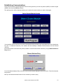
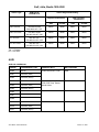
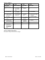
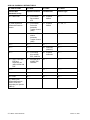
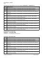
VDSPro
Instruction Manual
Version 2.09
Copyright Baum Tools Unlimited Inc.
October 17, 2000
Table of Contents
Disclaimer, Limit of Liability and Acknowlegement . . . . . . . . . . . . . . . . . . . . . . . . . . . . . . . . . . . . . . . . . . . . . . . . . . 3
Introduction . . . . . . . . . . . . . . . . . . . . . . . . . . . . . . . . . . . . . . . . . . . . . . . . . . . . . . . . . . . . . . . . . . . . . . . . . . . . . . . 4
Software Installation . . . . . . . . . . . . . . . . . . . . . . . . . . . . . . . . . . . . . . . . . . . . . . . . . . . . . . . . . . . . . . . . . . . . . . . . 4
Safety . . . . . . . . . . . . . . . . . . . . . . . . . . . . . . . . . . . . . . . . . . . . . . . . . . . . . . . . . . . . . . . . . . . . . . . . . . . . . . . . . . . 5
Self Diagnosis Operation . . . . . . . . . . . . . . . . . . . . . . . . . . . . . . . . . . . . . . . . . . . . . . . . . . . . . . . . . . . . . . . . . . . . . 8
Getting Connected . . . . . . . . . . . . . . . . . . . . . . . . . . . . . . . . . . . . . . . . . . . . . . . . . . . . . . . . . . . . . . . . . . . . . . . . . 10
Establish Communications
Select Control Module Screen . . . . . . . . . . . . . . . . . . . . . . . . . . . . . . . . . . . . . . . . . . . . . . . . . . . . . . . . . . . . 12
Manual Address Entry . . . . . . . . . . . . . . . . . . . . . . . . . . . . . . . . . . . . . . . . . . . . . . . . . . . . . . . . . . . . . . . . . . 12
Establish Communication Screen . . . . . . . . . . . . . . . . . . . . . . . . . . . . . . . . . . . . . . . . . . . . . . . . . . . . . . . . . . . . . 14
Functions . . . . . . . . . . . . . . . . . . . . . . . . . . . . . . . . . . . . . . . . . . . . . . . . . . . . . . . . . . . . . . . . . . . . . . . . . . . . . . . 15
Fault Codes . . . . . . . . . . . . . . . . . . . . . . . . . . . . . . . . . . . . . . . . . . . . . . . . . . . . . . . . . . . . . . . . . . . . . . . . . . 15
Control Unit Identification Screen . . . . . . . . . . . . . . . . . . . . . . . . . . . . . . . . . . . . . . . . . . . . . . . . . . . . . . 15, 16
Test Outputs . . . . . . . . . . . . . . . . . . . . . . . . . . . . . . . . . . . . . . . . . . . . . . . . . . . . . . . . . . . . . . . . . . . . . . . . . 17
Block Data . . . . . . . . . . . . . . . . . . . . . . . . . . . . . . . . . . . . . . . . . . . . . . . . . . . . . . . . . . . . . . . . . . . . . . . . . . . 17
Single Readings . . . . . . . . . . . . . . . . . . . . . . . . . . . . . . . . . . . . . . . . . . . . . . . . . . . . . . . . . . . . . . . . . . . . . . 18
Adaptation . . . . . . . . . . . . . . . . . . . . . . . . . . . . . . . . . . . . . . . . . . . . . . . . . . . . . . . . . . . . . . . . . . . . . . . . . . . 19
Code Control Module . . . . . . . . . . . . . . . . . . . . . . . . . . . . . . . . . . . . . . . . . . . . . . . . . . . . . . . . . . . . . . . . . . . 20
Login Function . . . . . . . . . . . . . . . . . . . . . . . . . . . . . . . . . . . . . . . . . . . . . . . . . . . . . . . . . . . . . . . . . . . . . . . . 20
General Engine Data . . . . . . . . . . . . . . . . . . . . . . . . . . . . . . . . . . . . . . . . . . . . . . . . . . . . . . . . . . . . . . . . . . . 21
ECU Unknown . . . . . . . . . . . . . . . . . . . . . . . . . . . . . . . . . . . . . . . . . . . . . . . . . . . . . . . . . . . . . . . . . . . . . . . . 21
Re-establish Communications Alert . . . . . . . . . . . . . . . . . . . . . . . . . . . . . . . . . . . . . . . . . . . . . . . . . . . . . . . . 22
DataView Program . . . . . . . . . . . . . . . . . . . . . . . . . . . . . . . . . . . . . . . . . . . . . . . . . . . . . . . . . . . . . . . . . . . . . . . . 23
Configure Program . . . . . . . . . . . . . . . . . . . . . . . . . . . . . . . . . . . . . . . . . . . . . . . . . . . . . . . . . . . . . . . . . . . . . . . . 24
Appendices
A - Troubleshooting the Software . . . . . . . . . . . . . . . . . . . . . . . . . . . . . . . . . . . . . . . . . . . . . . . . . . . . . . . . . . 25
B - Control Unit Applications . . . . . . . . . . . . . . . . . . . . . . . . . . . . . . . . . . . . . . . . . . . . . . . . . . . . . . . . . . . . . 28
C - Data Block Examples . . . . . . . . . . . . . . . . . . . . . . . . . . . . . . . . . . . . . . . . . . . . . . . . . . . . . . . . . . . . . . . . 33
D - Control Unit Programming Code List . . . . . . . . . . . . . . . . . . . . . . . . . . . . . . . . . . . . . . . . . . . . . . . . . . . . 38
E - Instrument Cluster Service Interval Reset Procedures . . . . . . . . . . . . . . . . . . . . . . . . . . . . . . . . . . . . . . . 45
F - Engine/Transmission Initiating Basic Setting . . . . . . . . . . . . . . . . . . . . . . . . . . . . . . . . . . . . . . . . . . . . . . 46
G - Procedure After Restoring Electrical Power 1999 and later vehicles . . . . . . . . . . . . . . . . . . . . . . . . . . . . 47
H - Cabriolet SRS (Airbag) System 1990-94 . . . . . . . . . . . . . . . . . . . . . . . . . . . . . . . . . . . . . . . . . . . . . . . . . 48
Contact Information . . . . . . . . . . . . . . . . . . . . . . . . . . . . . . . . . . . . . . . . . . . . . . . . . . . . . . . . . . . . . . . . . . . . . . . . 49
VDSPro Instruction Manual
ver.2.09
2
DISCLAIMER
All information contained in this document is correct to the best of our knowledge. Errors may occur, therefore Baum
Tools Unlimited Inc. makes no warrantee, guarantee or assurance that damage may not occur from the use of this
information or equipment. The user takes all responsibility for its use.
LIMITATION OF WARRANTIES AND LIABILITY
The product is provided on an "as is" basis, without any other warranties or conditions, express or implied, including, but
not limited to, warranties of merchantable quality, merchantability or fitness for a particular purpose, or those arising by
law, statute, usage of trade, or course of dealing. The entire risk as to the results and performance of the product is
assumed by you. Neither we nor our dealers or suppliers shall have any liability to you or any other person or entity for
any indirect, incidental, special, or consequential damages whatsoever, including, but not limited to, loss of revenue or
profit, lost or damaged data or other commercial or economic loss, even if we have been advised of the possibility of
such damages, or they are foreseeable. We are also not responsible for claims by a third party. Our maximum aggregate
liability to you and that of our dealers and suppliers shall not exceed the amount paid by you for the product. The
limitations in this section shall apply whether or not the alleged breach or default is a breach of a fundamental condition
or term or a fundamental breach. Some states/countries do not allow the exclusion or limitation of liability for
consequential or incidental damages, so the above limitation may not apply to you.
ACKNOWLEDGMENT
Products mentioned in this manual are mentioned for identification purpose only. Product names appearing in this manual
or in the Scanner screen may or may not be registered trademarks or copyrights of their respective companies.
VW is a registered trademark of Volkswagen AG, Germany.
Audi is a registered trademark of Audi AG, Germany.
SEAT is a registered trademark of SEAT S.A., Spain.
SKODA is a registered trademark of SKODA automobilova a.s., Czech.
*NOTICE
The specifications, information, and illustrations contained in this manual are based on the latest information available
at the time of publication. The right is reserved to make changes at any time without notice.
This instruction manual tells you how to use the VDSPro software to perform diagnostic tests and find possible
locations of vehicle problems. It does NOT tell you how to correct the problems. Consult the manufacturer
vehicle service manual or other publication for repair instructions.
To take full advantage of the software, you should be knowledgeable and well trained in each of the vehicle computer
control systems described in this manual.
Service data that appear to be non-functional on some vehicles may be due to vehicle manufacturing design changes.
Always refer to the manufacturers specification for the month and year of production of the model in question.
3
VDSPro Instruction Manual
ver.2.09
INTRODUCTION
VDSPro Diagnostic Software consists of a suite of programs allowing you to communicate with and analyze
diagnostic information from the Volkswagen, Audi, Seat or Skoda automobiles from the 1988 096/097 automatic
transmission controllers through the ME7.X engine controllers used in 2000 later model vehicles, as well as a variety
of other chassis, body and convenience feature computers.
VWTool.exe - This is the diagnostic program that communicates with the cars electronic system
controllers.
DataView.exe - Software that allows you to view, analyze and print the captured data block
information files from VWTool file that contains the saved block data from VWTool.exe.
ConfigVW.exe - Select the communications port and display units.
The package includes
! 1 3.5" diskette containing:
VDS-PRO Diagnostic Software version 2.09
DATAVIEW Analysis Software
CONFIGVW Port Selection Software
! Electronic Interface Cable (RS232 to ISO)
! Adapter for 1988-93 VW and Audi’s
! Adapter for 1994-98 VW and Audi’s (OBD II)
! this Software Users Manual
System Requirements
! IBM compatible 486/33 or better processor
! Windows 3.1, 3.11 or Windows 95/98/NT (100Mhz minimum CPU necessary)
! 4 Meg. Ram
! 1 Serial Port
SOFTWARE INSTALLATION
•
•
•
•
Start Windows (version 3.11, 95 or 98)
Insert the VDSPro Installation disk into drive A
From the Program Manager, choose Run from the File Menu
Type a:\Setup and press Enter
The Setup program will decompress and copy all files to the directory you have selected. These include certain DLL
files needed by Windows to run the programs. If these files are already present on your machine then you will be
prompted that they may be in use. Follow the on screen prompts to finish loading the program.
The Setup Program will then run the ConfigVW program. The ConfigVW program will allow you to select the serial
communications port to use and whether to display the speed and temperature in English or Metric units. The Setup
program will then create a Program group called VWTool and install three icons for the programs.
Common Installation Problems
The most common installation problem is serial port interrupt conflicts. On an IBM PC com1 and com3 share an
interrupt, com2 and com4 share another interrupt. This means that if you use com1 for the OBDII interface and there
is any serial device on com3, the software will not work due to the serial device on com3 stealing the interrupt.
Remove the serial device on com3 to correct the problem. Laptop users, beware of Infrared Ports on some newer
laptops. This port can be mapped over one of the serial ports or may be set to “poll” all interupts. This can cause
interrupt conflicts and loss of communications by the software. The address and interrupt used by the infrared port is
set in the BIOS of the laptop. It is best to disable the Infrared port during the use of the VWTool program.
Need a longer cable? The white cable included with the VDSPro software is a standard 9 pin serial extension cable,
also known as an RS232 DB9 serial cable. These cables can be purchased at most computer stores in variety of
lengths. We recommend not exceeding 50 feet as some controllers use very low voltage levels for communications.
If longer lengths are needed use only the highest quality cable available.
VDSPro Instruction Manual
ver.2.09
4
SAFETY
If you use the VWTool communications software in a laptop for analysis while driving, use a second person to
observe the computer screen.
At 30 mph a car travels 44 feet/sec. You cannot look at the computer screen, refocus your eyes, read the screen,
and refocus your eyes back to driving, in any reasonable length of time. Even a glance will divert to much attention
from driving.
Use a second person when doing drive tests!
There are electrical and mechanical hazards that are unique to each vehicle model type. Consult the factory
workshop manuals and all service bulletins for the vehicle you are working on. Workshop manuals can be purchased
at reasonable cost at the following sources:
Baum Tools Unlimited Inc.
PO Box 5867
Sarasota FL 34277-5867
800-848-6657 Toll Free USA/Canada
941-927-1414 Intl.
941-927-1612 Fax
www.baumtools.com
[email protected]
Call or write for a complete listing.
Bentley Publishing
1033 Massachusetts Ave.
Cambridge, MA 02138
800-423-4595
FedWorld
www.fedworld.gov/cleanair
5
VDSPro Instruction Manual
ver.2.09
The VDS Diagnostic Software System has been designed as an alternative to the VAG1551 and VAG1552
Volkswagen/Audi Diagnostic Analyzers. VDS software is IBM PC compatible and adds user friendliness, data storage
and graphing capabilities to all the features previously only found in the factory tools.
The VW/Audi Diagnostic program covers the following controllers
Engine
Transmission (Auto)
Brakes (ABS 3 and Later)
Airbag (SRS 2 and Later)
AC/Heating
Electronic Clutch
Suspension Control
Instrument Cluster (Including Service Interval Reset)
ASC (Anti-slip Control)
Automatic Roof Control System
Anti-theft System
Central Locking System
Power Seat Adjustment Control
Electronic Diesel Pump Control
Leveling Control
Interior Monitor
Headlight Range Control
Steering Wheel Control
Convenience Features
Radio
Seat/mirror Adjustment
Parking Aid
Auxiliary Heater
Features include
•
Read and reset Error Codes
•
Activate Components
•
"One Button" Service Interval Indicator Resetting
•
Alter Adaptation Values
•
Set ECU to Basic Values
•
Read Individual Data Block Values
•
Recode ECUs
•
Graphically Display, Store and Recall component values during road testing.
•
2 hour 'Flight Recorder' for extensive glitch capture.
Values that can be recorded include
•
O2 Value
•
RPM
•
Throttle Angle
•
Ignition Angle
•
% Engine Load
•
Engine Temperature
•
EGR Temperature
•
Intake Air Temperature
•
IAC Value
•
IAC Duty Cycle
•
Speedometer Reading
•
O2 at Idle (Learned)
•
O2 at High Speed, Low Load
•
O2 at High Load
•
Battery Voltage
VDSPro Instruction Manual
ver.2.09
6
VDSPro works on the following specific systems
Volkswagen engines
PG
DIGIFANT I
RV
DIGIFANT I
2H
DIGIFANT I
9A
CIS-E MOTRONIC
AAA
MOTRONIC 2.9/5.9
ABA
MOTRONIC 2.9/5.9
ACC
MONO MOTRONIC
All 1998 and newer engines.
10/90-Newer
10/90-Newer
10/90-Newer
10/90-Newer
1992-95/1996-Newer
1992-95/1996-Newer
1993-Newer
Audi Engines
3A
1989-90
3B
19907A
1990AAN
1992
ABH
YES
MC
MID 1989
MC
MID 1989
NF
California models only
NG
1988PT
1990
All 1998 and newer engines.
All diagnosable optional subsystems on these models (automatic transmission, ABS, SRS...etc).
*Other engines do not have high speed output. Such engines may be diagnosed with the jumper wire supplied under
the rear seat.
A more complete listing of applicable controllers is in Appendix B page 28.
--------------------The program is 16 bit. It has not been tested under OS/2.
7
VDSPro Instruction Manual
ver.2.09
SELF DIAGNOSIS OPERATION
All electronic control systems in a car function in similar ways. The sensors supply information to the control unit as to
the present operating state of the vehicle. The control unit analyzes this information, applies a control strategy, then
adjusts the output elements, to achieve the desired results. The control unit then takes inputs from other sensors to
detect weither the adjustment is correct to maintain optimal operation. These sorts of sensors include exhaust Oxygen
(O2 or Lambda sensors) and pressure sensors.
An example of this type of control system is the engine coolant temperature. The modern day car is required to start and
run smoothly under all conditions, cold to hot and idle to full load. The control unit requires information regarding the
engine temperature in order to make decisions on how these functions are to be performed. This information is supplied
by the Engine Coolant Temperature (ECT) sensor (G62). The ECT sensor is located so that it is in the constant flow of
engine and measures the temperature of the engine. The ECT then sends this engine temperature to the control unit in
the form of a voltage level. The control unit then applies the strategy determined by the factory engineers to regulate the
proper ignition angle, injection timing, and idle speed stabilization. The controller then adjusts these output control
elements. The engine temperature is also used by several other system functions, such as:
Knock control system (KS)
Lambda control system (Fuel mixture)
Fuel tank ventilation system (EVAP)
Exhaust gas recirculation system (EGR)
The Engine Coolant Temperature Sensor is a Negative Temperature Coefficient (NTC) thermistor which reduces its
resistance as the temperature increases. This means that the voltage measured at the controller increases with
increasing temperature.
The measuring range is -35 0C to 120 0C. This is specified by the software in the controller and any temperature higher
or lower is considered as faulty or as an implausible (out of range) reading. The fault is then stored in the fault memory
of the controller. This type of fault is known as a Component Malfunction Fault.
The controller stores three numbers for each fault it detects. First is the Fault Source which describes the component
that was checked. Second is the Fault Type which is information regarding the electrical state at the time of the fault (
Open, Short, High, Low, Etc.). Third is whether the fault is permanent or intermittent. A fault is only stored as permanent
if it is present for a specified period of time.
If the controller recognizes that the temperature signal is no longer being received, it will substitute a value (e.g. 80 0C),
to ensure continued operation and “log” a fault in the fault memory of the controller. This sort of substitution will cause
rough running during the cold start and during the warm-up phase.
The Service Tool will interrogate the controller fault memory, read the fault numbers, translate the numbers into text and
display the text on the computer screen.
Example #1:
00522
Engine Coolant Temperature Sender - G62
Open circuit / Short circuit to positive ( / Intermittent )
now known under OBD-II (includes VAG and SAE code) as
16500 P0116 Engine Coolant Temperature Circuit - G62
Range/Performance Problem ( / Intermittent )
This fault is due to the engine coolant input reading 5 volts. This would correspond to a temperature of minus 35 (-35)
C.
0
There are two possible causes:
There is an open circuit in the wiring. As a result of the “pull- up” resistor in the controller, the engine temperature
sensor indicates a voltage of 5 volts.
A short circuit in the wiring to battery voltage, will also result in a 5 volt reading at the engine temperature
controller input.
VDSPro Instruction Manual
ver.2.09
8
The controller is not able to distinguish between the two possible causes of the fault. The “/ Intermittent” tells you that
the fault occurred for brief period of time and is possibly due to a loose connection.
Example #2:
00522
Engine Coolant Temperature Sender - G62
Short circuit to earth/ground
now known under OBD-II (includes VAG and SAE code) as
16501 P0117 Engine Coolant Temperature Circuit Low Input - G62
The voltage of the engine temperature input is 0 volts. This would be a temperature of greater than 1200C. This fault is
possibly due to worn insulation in the wiring harness or a defective sender.
If the adjustments made by the control unit are insufficient to maintain optimal operation or allow exhaust emissions to
exceed standards then a System Malfunction Fault will be stored.
Examples of system malfunction faults are found in the;
Lambda Control System
EVAP Control System
Secondary Air System
etc...
These codes are the result of conditions not being met to maintain proper operation of the engine.
One of the most common System Malfunction Faults is the Oxygen Sensor (Lambda) Control Fault.\
Example #3:
00537
Oxygen Sensor (Lambda) Control
now known under OBD-II (includes VAG and SAE code) as
16554 P0170 Fuel Trim - Malfunction (Bank 1)
This code is stored when the controller detects excessive deviations in the air-fuel mixture (too rich or too lean) for longer
than 10 seconds. This is may be caused by faulty O2 sensor, in which case an O2 sensor code is stored as well.
Other possible causes are:
Fuel tank ran empty
Incorrect Fuel Pressure
Injector valve defective or coked
Engine Temperature Sensor defective
Secondary air leak
Fuel evaporation control system defective
Air Mass Meter defective
O2 sensor aging (slow response)
Combustion disturbed by mechanical failure (Spark plugs, compression, intake/exhaust valves, ...etc.)
Please note, the controller detects faults in input or output circuits. An electrical circuit consists of: wiring harness,
connectors, and sensors. To troubleshoot a specific circuit consult the workshop manuals for detailed test instructions
and troubleshooting.
9
VDSPro Instruction Manual
ver.2.09
GETTING CONNECTED
Connect the 9 pin RS232 DB9 connector to the serial port of the computer which will run the software. Next connect the
appropriate connector to the vehicle under test.
VOLKSWAGEN
Golf, Jetta, Corrado, Passat, Cabriolet (1988-93)
Diagnostic connector is located in the gear-lever box. Remove
shift lever cover. Connect the Black and White Service Tool Connectors to the matching connectors under the shift lever
cover. For the Cabriolet model the Yellow connector is fr transmission diagnosis and the Red is for SRS.
For some Golf models, the connector is between the seats behind the ashtray.
Some 1993 model year cars
Unclip the cover located below the heating / ventilation controls.
Connect the Black and White Service Tool Connectors to the matching connectors under the shift lever cover.
Golf, Jetta, Cabrio, GTI (1994-99)
Diagnostic connector is located on center of the dashboard, beside the ashtray.
Remove the ash tray and slide the cover to expose the OBDII connector.
Connect the 16 pin OBDII Service Tool connector.
Passat (1994-99)
Diagnostic connector is located on right side of the instrument panel.
T4 Eurovan
Diagnostic connector is located in the fuse box under driver side dashboard.
New Beetle
Diagnostic connector is located under dash, left lower side above the clutch pedal.
VDSPro Instruction Manual
ver.2.09
10
AUDI
80, 90 (1989-93)
Diagnostic connector is located in the engine compartment, under driver side fuse box,
in the drivers footwell near pedal cluster or behind stereo.
A3, A4 (1988-96)
Vehicle diagnostic connector is located in center console toward rear seat beside the
ashtray.
100, A6 (1988-93)
Diagnostic connector is located in the engine compartment or under driver side fuse
box.
100, A6 (1994-99)
Diagnostic connector is located in the center console next to the parking brake.
A8 (1990-93)
Diagnostic connector is located in the passenger footwell, under carpet.
A4, A8, Cabriolet (1997-00)
Diagnostic connector is located under dash, left of the steering column.
200
Diagnostic connector for SRS, below the climate control head and the ash tray housing.
11
VDSPro Instruction Manual
ver.2.09
Establishing Communications
Once connected to the vehicles diagnostic socket turn the ignition key on to the run position (KOEO) or start the engine
(KOER). Now start the VWTool software.
The opening screen will be displayed allowing you to select the control module you wish to interrogate.
Select Control Module Screen
You can select which Control Unit you wish to communicate with by clicking on the appropriate button or by using the hot
key (ALT + Underlined Character). The software will then attempt to establish communications with the selected
controller.
If the control module is not listed it may still be possible to communicate with the controller by using the Manual Address
Entry feature.
Manual Address Entry
To activate Manual Address Entry click once on the version number displayed on the main screen. This will activate the
Entry screen.
Next you will need the decimal number for the controller you wish to query.
VDSPro Instruction Manual
ver.2.09
12
Below is a list of known controllers and their ID numbers.
Controller ID
Number
System
08
Air Conditioning/Heating Controller
15
Airbag (SRS)
57
Airbag (SRS) - Cabriolet (1990-93) only
22
All-Wheel drive
18
Auxiliary Heating System
03
Brake Electronics (ABS)
45
Car Interior Alarm System
46
Central Comfort System Control
35
Central Locking System
12
Clutch Electronics
41
Diesel Pump Electronics
09
Electronic Switchboard
75
Emergency Call System
02
Gearbox Electronics
55
Headlight Control
25
Immobilizer
17
Instrument Cluster
34
Leveling Control
01
Motor (Engine) Electronics
37
Navigation System
76
Parking Control
56
Radio Control Module
36
Seat Position Control - Drivers Side
66
Seat/Mirror Memory System
47
Sound System
16
Steering Wheel Electronics
26
Sunroof Control
14
Suspension Electronics
65
Tire Pressure Monitor
24
Wheel Traction Control
Next press Send Address and the controller will be called.
If the controller does not respond it may be non standard or too new for the VDSPro software to identify. This is the case
with many 2001 and later controllers utilizing the ISO14230 communications protocol.
13
VDSPro Instruction Manual
ver.2.09
The VWTool software will make three attempts to establish communications with the selected controller. The software
will show the following Alert Box to inform you what it is doing.
Opening Interrogation Screen
Each attempt takes four seconds. If after three attempts the Service Tool cannot establish communications with the
controller, the following Alert Box will be displayed and you will be returned to the Select Module Screen.
If communications with the controller cannot be established check the following items.
Ignition Switch is in the RUN position
The VDSPro Cable Connections are intact
The vehicle battery is at least 10 volts
If still no communication is received follow the troubleshooting in Appendix A (page 25).
VDSPro Instruction Manual
ver.2.09
14
When VWTool establishes communications with the select module, the Electronic Control Unit Identification Screen is
displayed.
Control Unit Identification Screen
The top part of the screen will contain the control unit identification numbers. This information can be reread at any time
by clicking the Control Unit Info button.
The bottom part of the screen contains the Main Function Buttons. These are the functions the software is capable of
for this control unit type. Not all functions are supported by all controllers. Refer to the workshop manuals to determine
which functions are supported for each controller. A partial listing can be found in Appendix B (page 28).
If you select an unsupported function, the Service Tool will display the Unknown Function Warning Box and return to the
Control Unit Identification Screen.
The rest of this document will explain each function button.
VWTOOL FUNCTIONS
Fault Codes
The Fault Code function will interrogate the Control Unit and display the Fault Code Number (sometimes referred to as
a Diagnostic Trouble Code or DTC), the Fault Source, and the Fault Type in the Display window. The top line will display
15
VDSPro Instruction Manual
ver.2.09
the total number of Faults detected. The scroll bars on the right side will allow the screen to scroll up or down if several
faults are detected.
Note: Click on the scroll bar. If you hold down the mouse button for more than 1 second, you will lose communications
with the controller and VWTool with have to reestablish communications.
Please refer to the workshop manual to determine the operating mode (Example: Engine running or engine off) to
accurately read the Fault Codes.
To erase the fault codes, click on the Erase Error Codes Button. VWTool will erase the fault codes stored in the
controller. Now wait 10 seconds, then re-interrogate the controller. The software will display any new or persisting fault
codes.
Control Unit Information Function
This function displays the control unit identification numbers. The display appears when you first establish
communications with any control unit.
The Computer ID Number box contains the VW part number of the controller.
The Components Box will contain the type of component (Engine, Transmission, Etc.) and the identification of the
software being used by the control unit (If the software ID exists in the control unit). The Software Coding Box shows
the current Coding of the Controller.
The unlabeled box on the lower right can contain two different types of numbers.
If the controller supports Software Coding, the box will contain the letters “WSC” and a 5 digit number. WSC stands for
WorkShop Code and is the number of the last shop to code the controller. The WSC number for the manufacturer of the
controller is WSC 00000. The assembly plants have numbers generally beginning with 6XXXX and each point of entry
and each dealer is assigned a number.
Baum Tools Unlimited Inc. Inc. uses WSC #00222.
it is recommended that independent repair facilities use WSC #01283
If the controller does not support Software Coding, the box will contain the Bosch or manufacturers part number of the
controller.
VDSPro Instruction Manual
ver.2.09
16
Test Outputs Function
This function tests the activation of electrical components by the controller. It can only be used when the ignition is in
the Key On Engine Off (KOEO) position (engine not running). The Output Active Box will show which output is presently
active (Output buzzing or output on) and any special notes will appear in the Note Box.
To change to the next output click on the Next Output Button.
The order in which the outputs activate is determined by the control module. To get the sequence of the outputs active,
refer to workshop manual.
If the output shown in the Output Active Box is not active, check that output’s plug connection, wiring harness, or the
electrical/mechanical part for faults. When you are done with the Output Test Function, click the END Output Test
Button, this will end communications with the controller and return you to the Select Module main screen.
Block Data Function
Data Display
The top four displays contain the data block information read from the car controller. This data has been scaled to real
world units ( Example: RPM, Deg C, mS injection time, etc. ). A label describing the measured data will be displayed.
If the service tool software does not recognize the measured data, “Unscaled” will be displayed as the units and the raw
data ( 0 - 255 ) will be displayed in the data display. If “Unscaled “ is displayed check the workshop manual to determine
what data is being measured for that block number.
Graph
The Raw Data ( 0 - 255 ) is plotted vertically for each data variable and is color coded to match the Data Display for easy
identification. The graph will display 100 samples horizontally before scrolling. The graph is useful for showing trends,
spikes, and O2 response time.
17
VDSPro Instruction Manual
ver.2.09
The VWTool software reads a data block 3 to 4 times a second. This is determined by the Electronic Control Unit. The
graph represents approximately 30 seconds of data.
This information can be continuously recorded to the PC (See Save Data to File Button on page 18) and reviewed using
the DATAVIEW software package.
Remember, the graph is of the raw data (0 - 255), the data display shows the raw data scaled to real world units.
Change to Basic Settings
Click this button to go to the basic setting mode. This forces the controller to fixed values used for defaults when a
component failes. (Example: The Evaporative purge system Off). Please refer to the workshop manual for more
information on the effects the basic setting mode has on the controller.
*** Warning! *** The basic setting must only be performed in the operating state recommended for the vehicle. For
example, Engine temperature must be above 80 0C. For the recommended state refer to the workshop manual. Changing
to Basic Setting when the engine is cold can cause stalling and even damaging knock conditions..
Block Selection
The Data Blocks are predetermined by the controller and are different depending on the make, model and system type.
It is imperative to have the Factory repair Manuals in order to properly interpret this data.
There are three ways to select the block data to monitor.
Click the Enter Block Number text box and enter the block number using all 3 digits, then click the Accept button.
The software has been set up to allow easy access to the first 7 data blocks by just clicking on the block # button. To
access all higher data blocks use the Next button or enter the data block number directly into the Enter Block Number
text box.
Please refer to the workshop manual to determine what data blocks are available and the diagnostic interpretation and
procedures that use the data.
Click on one of the Data Block Buttons. The first 7 data blocks are usually “General Controller Data”.
Click on the Next or Previous Buttons to scroll through data blocks.
See Appendix C (page 33) for some sample Data Blocks.
Save Data to File Button
Selecting this button will save the incoming block data to the file “Capture.dat”. Click this button again to stop saving the
data.
Note: When you save data to file the previous contents of “Capture.dat” are lost. Use DataView or DOS to rename
“Capture.dat” file if you want to save the contents.
Main Functions Button
Clicking this button will return you to the opening Main Functions screen.
Single Readings Function
This function allows you to display an individual data channel. Individual channels that are supported by the controller
are listed in the Factory Workshop manual.
VDSPro Instruction Manual
ver.2.09
18
To read an individual channel, click on the Channel Number Text Box and enter the desired channel number. Press the
Enter key to accept the number.
The reading displayed is Unscaled (0 - 255).
Click on the Exit Button to exit the Single Reading Function.
Adaptation Function
Refer to the workshop manual on Adaptation before you attempt to use this function.
The Adaptation Function allows you to alter the learned correction values into the controller (Examples: Injector Open
Time, Idle speed, etc...).
Adaption values are altered in three steps:
1. Read Present Value
2. Test New Value
3. Store New Value in Controller
Read Present Value - Select the Channel Number Text Box and enter the channel number (2 digits). Press the Enter
key to accept the channel number. The VWTool software will interrogate the controller for the present value and any
relevant data the controller wants to send. The relevant data (if present) will be displayed in the top four boxes. The
present data value will be displayed in the Present Value Box.
Test New Value - Click on the New Value Text Box and enter the new value to test (3 digits). Press the Enter key to
accept the new value. The VWTool software will send the temporary new value and interrogate the controller. The
Present Value display will change to the new value and the relevant data display will reflect how the new value affects
the system.
Store the New Value in the Controller - If the new value had the expected result, you can make it permanent by clicking
the Save Button.
If you do not want to save the new value and revert back to the original value, click the Exit Button.
If you want to reset ALL adaptation values to the original factory settings, click the Reset All Button.
19
VDSPro Instruction Manual
ver.2.09
Code Module Function
*** Warning! *** You must refer to the workshop manual when using this function.
The Code Module Function enables you to adapt the operation of the electronic controller to different conditions.
Examples:
•
•
•
•
Different engine and transmission combinations.
Different fuel qualities.
Different emission standards.
Country of sale requirements.
Only the workshop manual or the VW/Audi technical site on the Internet will list the proper Coding for a particular model!
The tech site is http://tech.vw.com .
To change the coding of a control unit, click on the Input Code Number text box and enter the new coding number. Click
on the Accept button to change the Coding or the Cancel button to make no change and exit this function. If you click the
Accept Button, the service tool will code or recode the control unit and display the Control Unit Information Screen. The
software coding box will show the new Coding.
Note: On 1996 and later models you must do a successful Login Function before you can code or recode some control
units.
Login Function
This function is used on later models (1995/96 up) and allows you to enter a WSC number or a password number
(password numbers are contained in the workshop manual).
An example of controllers requiring WSC numbers are Engine controllers. Also Instrument cluster reset functions require
the use of a Login WSC number.
Examples of controllers requiring password numbers are Climatronic A/C controllers and Radios.
You must complete a successful Login to change the controller Coding. Note: you get only one chance to enter the
correct number. If you enter the wrong number, turn Off the ignition, wait 5 seconds, turn On the ignition, reestablish
communications, select the Login Function again and enter the correct Login number.
If a controller does not require a Login number it will respond with the Function Not Supported dialog box (page 21).
VDSPro Instruction Manual
ver.2.09
20
General Engine Data
This function displays Data Blocks 1-6 at the same time. The General Engine Data display gives an overall view of the
present state of the engine. The General Engine Data Function only works on 93 and later Golf III’s, Jetta III’s, and 92 up Corrado’s. The update rate of this display is slower than reading an individual Data Block, but is faster and more
convenient than scrolling through all six Data Blocks.
ECU Unknown Function
This warning box appears when the VWTool software tried to perform an illegal function or a function unsupported by the
control unit.
There are three main reasons why the function cannot be performed.
The control unit does not support this function.
Example: Mono-Motronic engine controllers and some ABS controllers do not support Block Data functions or data block
funtions other than 000.
The Function cannot be performed at this time.
Example: The engine is running and you try the Test Outputs Function. (Engine NOT running and ignition ON, is the
proper mode for the Test Outputs Function.)
You entered an improper number.
Example: Data Block #999, Individual Reading Channel #999.
Check the workshop manual for the proper procedure and / or functions available for a particular model.
21
VDSPro Instruction Manual
ver.2.09
Reestablish Communications Alert
This Alert Box will appear if the VWTool software has lost communications with the controller. The software will make
three attempts to reestablish the communication link and continue with the present function.
If you receive frequent Reestablish Communication Alerts, Please check the following possible causes.
Check all connections on the interface cable.
Check that the vehicle voltage is at least 10.0 volts.
Check that the cable is not near - spark plug wires, ignition coil, electric motors, or fluorescent lights.
If you are using a IBM serial extension cable with the VDSPro interface, it should be less than 100 feet and of the highest
quality possible.
Maximum allowable resistance in the cable is 12ohms over the entire length.
VDSPro Instruction Manual
ver.2.09
22
DataView Program
Open File
From the File Menu select Open. Choose the file you wish to view. The data will be displayed on the screen.
Cursors
Use the left or right cursor scroll bars to move the cursors to any data point of interest. The data at the cursors will be
displayed in the display boxes. On the cursor scroll bars, click on the arrow to move one data point at a time, Click on
the area between the arrow and the position indicator to move 20 data points at a time, and click and hold the position
indicator to move larger increments.
Zoom Buttons
The Zoom IN button will redraw the graph with the data between the cursors. The Zoom All button will display all the data
in the file. Use the Zoom buttons to magnify a data point of interest.
Print Screen
The Print Screen button will send a bit map of the screen to the default Windows printer.
File Save as
The File save will allow you to save the present data to any file name. Use this command to rename the “Capture.Data”
file to another name. Remember the “Capture.Data” file is erased every time the block data Save to File in VWTool is
used.
23
VDSPro Instruction Manual
ver.2.09
Configure Program
The Configure program allows you to select the communications (serial) port that the interface cable will use.
You can also select the display units (Metric or British Units) for Vehicle speed and Temperature.
The Accept button will store the selected setting in the VWTool.ini file which is read every time the VWTool program is
started.
The Cancel button will exit the program and not save any changes.
VDSPro Instruction Manual
ver.2.09
24
APPENDIX A
Troubleshooting
VDSPRO
Installation Problems:
Q: The error message “Cannot access A:\XXXXX.DLL because destination file is already in use.” appears
and when I click on OK the installation process halts. What’s wrong?
A: This most often occurs when running the Windows 98 SE operating system. The error message means that Windows
is currently utilizing one of the “Run Time Libraries” needed by Visual Basic applications. To successfully install, shut
down Windows and restart in “Safe” mode. To enter “Safe” mode press and hold the CTRL key after the Bios status
screen (most computers issue a beep sound after the bios status message). Then just continue installing the software.
Q: After installing the new version of VDSPro I still get the old version when I start the program. What’s
wrong?
A: Delete all the programs in the VWTOOL directory then reinstall the software.
Running Problems
Q: I can’t get the program to communicate with the car.
A: Here are some things to check.
1) Check that the car is equipped with on board diagnostics (OBD) or OBD-II. This can be determined by the presence
of a CHECK ENGINE, MIL or SERVICE ENGINE light display on the dash. Cars without this feature do not have
VW/Audi OBD or OBD-II. For OBD-II vehicles verify the presence of the J1962 (16-pin) OBD-II socket in under the
dash, along the centerline of the car or in the dash. Confirm the presence of pin #7 and pin #15. Note: After 1995
not all vehicles require pin #15, but all must have pin #7.
2) Next, verify the presence of a COM port on your computer. COM or serial ports are 9 or 25 pin male connectors.
Printer ports are 25 pin female connectors. Printer ports cannot serve as serial ports. The 9 pin connector on the
computer is traditionally specified as serial port COM1, built-in Modems are traditionally designated serial port COM2.
Infrared serial ports should be disabled.
3) Check for other COM port devices. These devices can include:
MODEM or FAX/MODEM
MOUSE
NETWORK CARD
GPS CARD
4) Verify the serial port COM specification is available to software.
Windows 3.1 or 3.11 - Choose the MAIN program group. Double click on the MS-DOS PROMPT icon. Type MSD and
press ENTER. This will start the Microsoft Diagnostic Software. After analyzing your system, the program will inform
you that Windows is currently running. Choose OK. The program will then display a screen which will show the
system components. Look for COM Ports on the right hand column of the screen. It should show at least 1 COM port.
Press the C key and the COM Port information will be displayed. The address of the COM ports should correspond
to the following chart. Press ESC. Now press Q. This will display the INTERRUPT (IRQ) numbers.
25
Baum Tools Technical Support
January 8, 2000
The interrupts should correspond to the following chart.
Port # Address
COM1 03F8H
COM2 02F8H
COM3 03E8H
COM4 02E8H
Interrupt
IRQ4
IRQ3
IRQ4
IRQ3
Now press ESC and look for the MOUSE on the left of the screen. Press U. This displays the mouse information. If
the mouse is a serial mouse there may be a conflict with the serial ports. Press ESC and check for network cards
under the NETWORK section. If cards are present conflicts may occur with the serial ports.
Windows 95 - Choose CONTROL PANEL from the MY COMPUTER icon. Next choose SYSTEM. Choose the
DEVICE MANAGER tab. Go down the list to PORTS (COM & LPT). Double click on the PORTS icon, then double click
on the first Communications Port displayed. This should be COM1. Then click on the RESOURCES tab. The interrupt
Request and Input Output Range should correspond to the chart above. Check the CONFLICTING DEVICE LIST at
the bottom of the screen. It should report NO CONFLICTS. Repeat for all Communications Ports. Check for other
devices such as MODEMS and NETWORK cards which may conflict with the serial ports.
Communication error messages returned by Windows
8006 - No COM port of this number is installed in the computer
8010 - Two devices are competing for the same COM port IRQ (interrupt request).
8013 - Device already open by another device. (Another device is already using this port.)
5) If all the above is satisfied, we next need to check for software conflicts. This can occur when TSR programs loaded
at startup "POLE" the serial ports. First check for any programs started by Windows. These generally can be found
in the STARTUP program group. Temporarily disable any programs you find. Reboot your computer and attempt a
diagnosis as in step 2.
6) Next check the CONFIG.SYS and AUTOEXEC.BAT files for TSRs which may conflict. These can be anti-virus
software, fax/modem fax software, DOS mouse drivers and network drivers. If you are unsure of what these files
consist of please email or fax me copies at 415-566-0694 USA for analysis.
7) “Runtime Error 5" can be caused by corrupted DLL files, faulty disk drives or display drivers lower than 800x600
resolution. Most often resetting of the display to 800x600 resolution or higher solves this problem.
8) To see if any communications is occurring, start the program.
For VDS-Pro click once on the word SELECT in the opening screen. You will see no change at this time.
Next click on ENGINE to attempt communication.
Two boxes should appear at the top of the next screen marked TRANSMIT and RECEIVE.
The program should send a string of zeros to the cars computer. This can be seen in the TRANSMIT box. The
RECEIVE box should go blank then show the hexidecimal (base 16) output from the car. If the communications fails,
email the information strings found in the TRANSMIT and RECEIVE boxes to [email protected] for analysis.
9) “No characters received from interface. “ This usually indicates that the vehicle is not OBD-II compliant.
Baum Tools Technical Support
January 8, 2000
26
Using MSCONFIG
1.
Go to START | RUN and type "msconfig" (without the quotes) in the "Open" box; click on "OK".
2.
Under the General tab, click on "Selective startup"
3.
Click on the Config.sys and Autoexec.bat tabs and remove all checks.
4.
Click on the Win.ini tab, click on the "+" sign next to [windows] and remove the checks for any run= and load=
entries.
5.
Click on the Startup tab and remove all checks EXCEPT for ScanRegistry and SystemTray.
6.
Click on "Apply" and restart the system. If the problem is resolved, you can add the checks back one at a time
(restarting the system each time) until you find which entry is causing the problem. Once the program has been
identified, then place all the checks back into the appropriate boxes.
ACCESSING THE BIOS
Bios Mfg.
Key to Depress
AMI
[F1] or [Del] on bootup
AST
[Ctrl]-[Alt]-[Esc] on bootup
Award
[Del] on Bootup
Compaq
[F10] on Bootup
Phoenix
[F2] on Bootup
IBM PS1 &Value Point
[F1] on Bootup
Other Systems
Unless the POST (Power On Self-Test) message displays the BIOS access method
or it is written in the documentation; Qualtel, DTK, Kaypro, AST, IBM, NEC, NCR,
and other older systems will either have a POST message or include a
setup/diagnostics disk that includes a BIOS configuration procedure.
27
Baum Tools Technical Support
January 8, 2000
APPENDIX B
VW/Audi Controllers Ability Cross reference
Note: X or date represent feature is available, dash (-) represents not available. Chart is still under development .August 24, 2000
ECU ID
Fault Codes
R/C
Output Diagnostic
Test Mode
Basic Setting
Read Data Blocks
Adaptation
Readiness
Code
Individual
Component
Monitoring
Code ECM
1Z (diesel)
11/93-
X
X
X
X
X
-
-
-
-
2H DIGIFANT II
(49 state)
-
-
-
-
-
-
-
-
-
2H (Digifant I)
10/90-9/92
-
X
-
-
X
-
-
-
-
3A CIS-Motronic
1989-90
-
Blink Only
-
-
-
-
-
-
-
3B Motronic MPI
3/90-
X
-
-
X
-
-
-
-
7A Motronic MPI
3/90-
X
-
-
X
-
-
-
-
9A (CIS-E Motronic)
1/90-9/92
X
-
-
X
-
-
-
-
-
-
-
-
X
X
X
-
-
-
ENGINE TYPE
(Code can be found on
vehicle data plate)
AAA (M2.9)
1993-94
X
X
X
X
X
AAA (M5.9)
1995-97
X
X
X
X
X
AAB (diesel)
-
-
-
-
-
AAF
X
X
10/91-
10/91-
X
AAH Motronic MPI
11/91-
X
X
X
X
X
AAN Motronic MPI
1992-
X
X
X
X
X
AAZ (diesel)
10/93-
-
-
-
-
-
-
ABA (M5.9)
X
X
X
X
X
ABA (M2.9)
1994-95
X
X
X
X
X
Baum Tools Technical Support
-
10/91MMS 300 and
higher
MMS 100,
200, 300 only
MMS 300,
411 only
-
-
-
-
-
X
X
-
-
-
-
January 8, 2000
28
ECU ID
ABG (Digifant I)
10/90-9/92
ABH
?
ABH Motronic MPI
1991
29
Fault Codes
R/C
Output Diagnostic
Test Mode
Basic Setting
Read Data Blocks
Adaptation
Readiness
Code
Individual
Component
Monitoring
Code ECM
X
-
-
X
-
-
-
-
X
X
X
X
-
-
X
-
-
-
-
-
-
-
-
ACC (Mono Motronic)
10/92-95
X
X
?
?
X
ACU
X
X
X
X
X
AEB (M3.8.2)
8/97-8/99
X
X
X
X
X
X
AEG ( )
X
X
X
X
X
X
AES (M5.9)
X
X
X
X
X
AFC Motronic MPI
11/91-
X
-
-
X
-
AFC Motronic MPI
11/91-
X
-
-
X
X
-
-
L
L
X
X
-
-
-
-
-
-
-
AHA (M5.9)
8/97-
X
X
X
X
X
X
X
-
X
AHH (Diesel)
10/97-2000
X
X
X
X
X
-
X
-
X
ALH (Diesel)
X
X
X
X
X
-
-
-
X
ALL 1988 CIS-E
MODELS
-
Blink Only
Use fuel pump
relay jumper to
pull codes
-
-
-
-
-
-
-
APH (ME7.5)
2/99-
X
X
X
X
X
X
X
-
X
ATQ (ME7.1)
X
X
X
X
X
X
X
-
X
ATW (ME7.5)
9/99-
X
X
X
X
X
X
X
-
X
CS (Diesel)
-
-
-
-
-
-
-
-
-
CV AFC
-
-
-
-
-
-
-
-
-
DH (Digijet)
-
-
-
-
-
-
-
-
-
GX (CIS/CIS-E)
-
-
-
-
-
-
-
-
-
Baum Tools Technical Support
January 8, 2000
ECU ID
Fault Codes
R/C
Output Diagnostic
Test Mode
Basic Setting
Read Data Blocks
Adaptation
Readiness
Code
Individual
Component
Monitoring
Code ECM
HT (CIS-E)
-
-
-
-
-
-
-
-
-
JH (CIS)
-
-
-
-
-
-
-
-
-
JN (CIS/CIS-E)
-
-
-
-
-
-
-
-
-
MC CIS-E (1 KNOCK)
1988-7/90
-
Blink Only
-
-
-
-
-
-
-
X
-
-
?
-
-
-
-
MC CIS-E (2-knock)
7/90MV (Digifant II)
-
-
-
-
-
-
-
-
-
MZ (CIS)
-
-
-
-
-
-
-
-
-
-
Blink Only
-
-
-
-
-
-
-
NF CIS-E III (49 STATE)
-
NO
-
-
-
-
-
-
-
NG CIS-III
1988-90
-
Blink Only
-
-
-
-
-
-
-
PG (Digifant II)
-
-
-
-
-
-
-
-
-
PG (Digifant I)
10/90-9/92
?
X
-
-
X
-
-
-
-
PL CIS-E
-
-
-
-
-
-
-
-
-
PT
?
X
X
X
-
-
-
-
-
X
-
-
X
-
-
-
-
NF CIS-E III (CALIF)
PT Motronic MPI
1990RD CIS-E
-
-
-
-
-
-
-
-
-
RV Digifant II
-
-
-
-
-
-
-
-
-
X
-
-
X
-
-
-
-
-
-
-
-
-
-
-
-
-
096
X
X
X
X
097
X
X
X
098
X
X
X
X
01M
X
X
X
X
01N
X
X
X
X
RV Digifant I
10/90-9/92
UM CIS/CIS-E
TRANSMISSION
Baum Tools Technical Support
January 8, 2000
30
ECU ID
Fault Codes
R/C
01P
X
01V
X
Output Diagnostic
Test Mode
Basic Setting
Read Data Blocks
X
X
X
X
X
X
Adaptation
Readiness
Code
Individual
Component
Monitoring
Code ECM
ABS
Teves 02 ABS
Grey or Blue Plug
(1990-94)
Blink Only
Teves 02 ABS/EDL
White Plug
(1990-94)
X
From
8/91
ABS
(1992-96)
X
X
ABS/EDL
(1996-99)
X
X
ITT MARK 20 IE
1998-2000
X
X
ABS/EDL (Bosch 5.0)
1996-97
X
X
ABS/EDL (Bosch 5.3)
1998-2000
X
X
ABS/EDL/ASR
(Bosch 5.3)
1998-2000
X
X
X
X
SRS
X
X
X
X
SRS (ZAE)
X
X
SRS (VW)
1998-2000
X
X
SRS (Audi)
1997-1999
X
X
X
X
X
SRS (Airbag 8)
1999-2000
X
X
X
X
X
A/C
X
X
X
X
X
A/C (Audi)
1997-
X
X
X
X
X
X
X
X
X
X
X
EDL only
X
X
X
X
X
AIRBAG
X
X
X
X
CLIMATE CONTROL
31
Baum Tools Technical Support
X
January 8, 2000
ECU ID
Fault Codes
R/C
Output Diagnostic
Test Mode
Basic Setting
X
X
X
X
COMFORT SYSTEM
w/Power Windows
X
X
X
X
X
X
COMFORT SYSTEM
wo/Power Windows
X
X
X
X
X
X
Central Locking (Audi)
1996-2000
X
X
X
X
Ultrasonic Monitor
(1997-2000)
X
X
X
X
X
X
X
X
X
X
X
X
X
X
X
X
X
A/C Climatronic
Read Data Blocks
Adaptation
Readiness
Code
X
Individual
Component
Monitoring
Code ECM
X
BODY DIAGNOSTIC
X
ELECTRICAL
EQUIPMENT
Instrument Cluster (VW)
1998-2000
Instrument Cluster (Audi)
1996-99
Radio (VW)
X
X
X
X
X
Radio (Audi)
1998-2000
X
X
X
X
X
Anti-Theft
Ignition Keys
X
X
X
Cruise Control
L
X
Headlight Position
X
X
Seat/Mirror
Adjustment
X
X
X
Gateway Databus
X
X
X
Baum Tools Technical Support
X
X
X
X
X
January 8, 2000
32
APPENDIX C
VW Data Blocks for Engine
Data Block Group: 000
Display Field:
Indicated
Specification (digital)
Corresponding Value
1
ECT
182-224
80-110C
2
Engine Load
26-44
1.3-2.2ms
3
RPM
80-88
800-880rpm
4
O2 Factor
92-164
0.7-1.3
5
LTFT
83-241
0.87-1.22
Display Field:
Indicated
Specification (digital)
Corresponding Value
6
STFT (Part Load)
NA
NA
7
STFT (Full Load)
92-164
0.7-1.3
8
Air Correction
114-154
2.8-5.2Kg/h
9
Not Used
10
Ignition Angle
93-76
2.25-15o
Data Block Group: 001
Display:
Indicated
Specifications
RPM
Engine Speed
800-880 RPM
Engine Temperature (C)
Engine coolant temperature
80-110C
O2
O2 sensor factor
0.7-1.3v
Ignition Timing
Ignition (degrees)
2.25-15
Data Block Group: 002
Display:
Indicated
Specifications
RPM
Engine Speed
800-880 RPM
Injector timing
Injection timing period
2.8-5.2ms
Charging System
Battery voltage
12.5-15 volts
Exhaust Temperature
Exhaust temperature in Celsius
127.4 C (lowest figure displayed)
Data Block Group: 003
Display:
Indicated
Specifications:
RPM
Engine Speed
800-880 RPM
Load Signal
Engine load signal
0-5%
Throttle angle
Throttle valve angle
5-19 Degrees
Intake Temperature
Intake manifold temperature
Approximate ambient temperature
Data Block Group: 004
Display:
Indicated
Specifications:
RPM
Engine Speed
800-880 RPM
Load Signal
Engine load signal
0-5%
Km/h
Road speed signal
0 Km/h
xxxxx
Operating mode (5 digit number)*
See footnotes
Data Block Group: 005
Display:
Indicated
Specifications:
RPM
Engine Speed
800-880 RPM
Kg/h
Learned value for idle stabilization
2.8-5.2 kg/h
Duty cycle
Idle control valve
50-60%
Adjustment conditions
Not determined as of present
N/A
Data Block Group: 006
Display:
Indicated
Specifications:
O2
O2 factor
0.7-1.3 volts
x.x
Idle adaptation
0.87-1.22 volts
x.x
Part load adaptation
N/A
x.x
Full load adaptation
0.7-1.3 volts
33
VW - PASSAT CIS/MOTRONIC 9A
The engine controller of the 9A 16-valve found in the 1992 Passat has very little real time data available in it's
native data stream.
The one available data block, 000, contains the following in decimal 0-255;
Field
Description
Nominal Values
Value Range
1
Engine coolant temperature
0-255
2
Engine load
0-255
3
Engine speed
0-255
4
Idle stabilizer adaptive
0-255
5
Idle stabilizer working
0-255
6
Differential pressure regulator working
0-255
7
Differential pressure regulator adaptive
0-255
8
Vehicle speed
0-255
9
Switching values
0-255
Engine timing
0-255
10
Nominal values will be found in the Passat Official Factory Repair Manual for 1990-93.
34
Reading Individual Measuring Values Channel Numbers
Note: Disconnect EVAP canister purge regulator valve connector before checking channels 00 and 01.
Audi
Channel
35
Component
Range
00
Oxygen Sensor (02S) control factor for Cyl. 1-3
120-136
01
Oxygen Sensor (02S) control factor for Cyl. 4-6
120-136
02
02S 1 output voltage
300-600mv
03
02S 2 output voltage
300-600mv
04
Injection time, Cyl. 1-3
~2.3ms@idle
05
Mass Air Flow (MAF) sensor ground voltage loss
0-40mv
06
Duty cycle (control) for EVAP canister purge regulator valve -N80
0 (open)-255 (closed)
07
Duty cycle (control) for Idle Air Control (IAC) valve -N71
~128
08
Current regulation for IAC valve -N71
09
Throttle valve angle
0 at Idle
10
EGR temperature (via EGR temperature sensor -G98-)
C
11
Throttle Position (TPS) sensor -G69- output voltage
12-25
~19 at Idle
12
Ignition Map Switching
<128 Map 1 (Base)
>128 Map 2 (Retarded
Timing)
13
Ignition Timing with Knock Regulation and ISC
Ign. Timing in Crank
Degree
14
ECM battery positive voltage supply (B+)
10.56-14.56 Volts
15
Current road speed
Km/h
Volkswagen/Audi
SRS (Airbag)
Data Block Definitions
Display
Display
Group No.
Field
001
1
Designation
Display
Content
Definition of display
content
Correction
Check wiring by visual
Driver's Side Airbag
1111
Resistance OK
Igniter
0111
Resistance value too high inspection.
1011
Resistance value too low
Check circuit connections
1101
Short to Ground (GND)
for correct and secure fit while
1110
Short to positive (B+)
simultaneously watching
- VW N95
display.
2
Passenger's Side
1111
Resistance OK
Airbag Igniter
0111
Resistance value too high 1111 (resistance OK), then
1011
Resistance value too low
1101
Short to Ground (GND)
1110
Short to positive (B+)
- VW N131
If display content changes to
erase DTC Memory.
If wiring and connections are
OK and a malfunction is still
3
Left Seat Belt
1111
Resistance OK
Tensioner Igniter
0111
Resistance value too high displayed), erase DTC Memory
1011
Resistance value too low
conduct test drive and check
1101
Short to Ground (GND)
DTC Memory again
1110
Short to positive (B+)
- VW N153
indicated (1111 is not
If display content still
indicates
4
Right Seat Belt
1111
Resistance OK
Tensioner Igniter
0111
Resistance value too high
1011
Resistance value too low
If necessary, replace Airbag
1101
Short to Ground (GND)
Control Module - J234.
1110
Short to positive (B+)
- VW N154
Display
Display
Group No.
Field
002
1
Designation
Voltage supply (B+)
Display
Content
0
1
a malfunction, replace igniter.
Definition of display
content
Correction
Voltage too low
Check Battery Positive
Voltage
(B+), Check Generator (GEN),
Wiring Diagrams. Check
wiring
by visual inspection only
©Baum Tools Unlimited Inc.
October 17, 2000
36
Volkswagen/Audi
ABS
Data Block Definitions
Volkswagen
Display
Display
Group No.
Field
001
002
003
Designation
Display
Content
Value Not
Moving
Units
Correction
Check for variations in wheel
speed between all sensors.
Variation indicates damaged or
polluted sensors or high wire
resistance.
1
Wheel speed - Left Front
0-255
2-6
Km/h
2
Wheel speed - Right Front
0-255
2-6
Km/h
3
Wheel speed - Left Rear
0-255
0-2
Km/h
4
Wheel speed - Right Rear
0-255
0-2
Km/h
1
Wheel speed - Left Front
2-255
255
Km/h
2
Wheel speed - Right Front
2-255
255
Km/h
3
Wheel speed - Left Rear
0-255
255
Km/h
4
Wheel speed - Right Rear
0-255
255
Km/h
1
Brake Pedal Not Depressed
0
Brake Pedal Depressed
1
This is the speed at which the
ABS controller detected activity in
the pulse transmitters. This is a
good indicator of properly
functioning wheel sensors.
Nominal values are 1-6 Km/h.
High values indicate low voltage.
This tests the brake pedal stop
lamp switch and lamp circuit.
Audi
Display
Display
Designation
Group No.
Field
001
Condition
Display Value Not
Units Correction
Content Moving
1
Wheel speed - Left Front
1-19
1
2
Wheel speed - Right
Front
1-19
1
3
Wheel speed - Left Rear
1-19
1
4
Wheel speed - Right Rear
1-19
1
5
Brake Pedal
Not Depressed
0
Brake Pedal
Depressed
1
Brake Pedal
Not Depressed
0
Brake Pedal
Depressed
1
Voltage at ABS return
flow pump -V39-
Not Running
0
Running
1
ABS solenoid valve relay
Relay Open
6
7
8
Relay Closed
Km/h Check for variations in
wheel speed between
Km/h all sensors. Variation
indicates damaged or
Km/h polluted sensors or
high wire resistance.
Km/h
This tests the brake
pedal stop lamp switch
and lamp circuit.
No permissible
1
In all Audi’s, above 19Km/h (12mph) the OBD function of the ABS controller is terminated.
37 ©Baum Tools Unlimited Inc.
October 17, 2000
APPENDIX D - Control Unit Programming Code List
ENGINE CODING NUMBERS
VW
PASSAT 2.8L VR6 WITHOUT OBD-II
1
Manual Transmission without EGR
2
Automatic Transmission without EGR
3
Manual Transmission with EGR
4
Automatic Transmission with EGR
PASSAT 2.0L WITHOUT OBD-II
1 HS
Manual Transmission with EGR and EVAP
2 AG
Automatic Transmission with EGR and EVAP
PASSAT 2.8L VR6 WITH OBD-II
00000
Manual Transmission
00001
Automatic Transmission
PASSAT 2.0L WITH OBD-II
00006
Manual Transmission
00007
Automatic Transmission
JETTA/GOLF/GTI 2.0L WITH OBD-II
00000
Manual Transmission
00001
Automatic Transmission
EUROVAN 2.5L 5 cylinder
Not necessary to 1999.
EUROVAN 2.8L VR6 WITH OBD-II
00000
Manual Transmission
00001
Automatic Transmission
ECM codes for model year 2000 and later.
Engine
Manual
Automatic
ABS
1. 9 Liter TDI
No
Yes
Yes
1. 9 Liter TDI
No
Yes
Yes
1. 9 Liter TDI
Yes
No
Yes
1. 9 Liter TDI
Yes
No
No
1. 9 Liter TDI
Yes
No
Yes
1. 9 Liter TDI
No
Yes
No
1. 9 Liter TDI
No
Yes
No
2.0 Liter
Yes
No
No
2.0 Liter
Yes
No
Yes
2.0 Liter
Yes
No
No
2.0 Liter
Yes
No
Yes
2.0 Liter
No
Yes
No
2.0 Liter
No
Yes
Yes
2.0 Liter
No
Yes
No
2.0 Liter
No
Yes
Yes
©Baum Tools Unlimited Inc.
Airbag
Yes
No
Yes
Yes
No
Yes
No
No
No
Yes
Yes
No
No
Yes
Yes
Code
00001
00001
00002
00002
00002
00004
00004
00001
00011
00021
00031
00003
00013
00023
00033
October 17, 2000
38
Golf, Jetta, Beetle 1999-2000
Vehicle Type
ECM Part # /
EPROM Level
Vehicle Engine ECM Coding
5 Speed Transmission
AG4 Automatic
Transmission
ABS
No ABS
ABS
No ABS
Tier1 w/cruise
06A 906 018 BG
06A 906 018 P / V07
00000
00040
00001
00041
Tier1 w/o cruise
06A 906 018 BH
06A 906 018 AE / V06
00000
00040
00001
00041
LEV w/cruise
06A 906 018 J
06A 906 018 CR / V03
00000
00040
00001
00041
LEV w/o cruise
06A 906 018 J
06A 906 018 CQ / V03
00000
00040
00001
00041
Tier 1 = Federal
LEV = 50 State
AUDI
AUDI 2.8L V6 MMS 300
CODING
TRANSMISSION TYPE
EQUIPPED WITH
NOT EQUIPPED
00000
Manual
Heated O2 Sensor, EVAP
EGR
00001
Automatic (AG4)
00002
Automatic (HP18)
00003
Manual
00004
Automatic (AG4)
00005
Automatic (HP18)
Heated O2 Sensor, EVAP,
EGR, EGR Temp. Sensor,
Speed Limiter
00006
00007
00008
00009
Manual
00010
Automatic (AG4)
00011
Automatic (HP18)
39 ©Baum Tools Unlimited Inc.
O2 Sensor, EVAP, EGR
October 17, 2000
AUDI 2.8L V6 MMS 311
1ST AND 2ND DIGIT
3RD DIGIT
4TH DIGIT
5TH DIGIT
Exhaust Gas
Standard/Country
Special Functions
Transmission
Type
Vehicle Type
00 = -
0 = Front Wheel
Drive without
ATC
0 = 5-Speed
0= -
01 = USA with EGR
1 = Front Wheel
Drive with ATC
1= -
1 = 90, 90 Quattro
02 = Sweden and all
countries not 01,
03, 04, 06
2 = All Wheel Drive
without ATC
2 = Automatic
(097)
2 = A6, A6 Quattro Sedan
A6 Wagon
A6 Quattro Wagon
03 = South Africa no O2
sensor
3= -
3 = Automatic 097
(Phase 2)
3= -
04 = European Union
(EU) and Norway
4= -
4 = Automatic
(01K/01F)
4 = Cabriolet
05 = -
5= -
5= -
5= -
06 = California (Frt.
6= 6= 6= Wheel drive and
Automatic trans.
With EGR and
EVAP
ex. 01042 - USA, Frt. Wheel Drive w/o ATC, Auto Trans (01K/01F), Audi A6
AUDI 2.8L V6 MMS 400 WITH OBD-II
Not required. Coding of 01002 cannot be changed.
©Baum Tools Unlimited Inc.
October 17, 2000
40
AUDI 2.8L V6 MMS 411 WITHOUT OBD-II
1ST AND 2ND DIGIT
3RD DIGIT
4TH DIGIT
5TH DIGIT
Exhaust Gas
Standard/Country
Special Functions
Transmission
Vehicle Type
00 = With EVAP
0 = Front Wheel
Drive without
ATC
0 = 5-Speed
Manual
0= -
01 =With EVAP and
Differential Pressure
Sensor
1 = Front Wheel
Drive with
Automatic
Traction Control
(ASR)
1 = 6-Speed
Manual
1 = A4, TT
02 = -
2 = All Wheel Drive
without
Automatic
Traction Control
(ASR)
2= -
2 = A6
03 = -
3= -
3= -
3= -
04 = -
4= -
4 = Automatic
(01K/01F)
4= -
05 = -
5 = Front wheel
drive w/ASR,
ESP, CAN Bus
5 = 5-Speed
Automatic
5= -
06 = USA; TLEV With
EGR and
Secondary Air
(AIR) Vehicle with
LDP
6 = All wheel drive
w/ASR, ESP,
CAN Bus
6= -
6= -
07 = -
7= -
7= -
7= -
08 = -
8= -
8= -
8= -
09 = EGR
9= -
9= -
9= -
10 = With EVAP,
Differential Pressure
Sensor, EGR and
Secondary Air Injection
(OBD-II)
41 ©Baum Tools Unlimited Inc.
October 17, 2000
TRANSMISSION CODING
VW
Not required to 1998.
AUDI
Not required to 1998.
ABS CODING
VW
Passat 04505
AUDI A6 Front Wheel Drive
000 Manual
001 Automatic
AUDI A6 All Wheel Drive
Not required at this time.
SRS CODING
VW Airbags to 2000
VW
Chassis
Model
Index
(ECU Part # suffix)
Coding
A3
Golf/Jetta
D
J
T
00068
00074
00084
A3
Cabrio
D
J
T
ZF
00068
00074
00084
23110
A4
Golf/Jetta
C
J
00067
00074
B4
Passat
G
00071
B5
Passat
B
00066
NB
New Beetle
F
AQ
00070
16721
T4
Eurovan
M
AJ
00077
16714
A2
Corrado (Canada)
C
00067
©Baum Tools Unlimited Inc.
October 17, 2000
42
Audi Airbag III, V - 1995-97
00127
Audi Airbag up to week 35.98 for use with Control Modules “4B0959655D” or “4B0959655K only.
Code
Airbag Features
00004
Vehicles with Front Airbags, Front Seat Belt Tensioners and 2 Rear Seat Belt Tensioners
00006
Vehicles with Front Airbags, Front Seat Belt Tensioners and 3 Rear Seat Belt Tensioners
00104
Vehicles with Front Airbags, Front Side Airbags, Front Seat Belt Tensioners and 2 Rear Seat Belt
Tensioners
00106
Vehicles with Front Airbags, Front Side Airbags, Front Seat Belt Tensioners and 3 Rear Seat Belt
Tensioners
00115
Vehicles with Front Airbags, Front Side Airbags, Front Seat Belt Tensioners, 2 Rear Seat Belt
Tensioners, Belt Inquiry and Front Seat Occupied Sensor
00117
Vehicles with Front Airbags, Front Side Airbags, Front Seat Belt Tensioners, 3 Rear Seat Belt
Tensioners, Belt Inquiry and Front Seat Occupied Sensor
00204
Vehicles with Front Airbags, Front Side Airbags, Rear Side Airbags, Front Seat Belt Tensioners and
2 Rear Seat Belt Tensioners
00205
Vehicles with Front Airbags, Front Side Airbags, Rear Side Airbags, Front Seat Belt Tensioners, 2
Rear Seat Belt Tensioners and Seat belt Fastened Sensor
00206
Vehicles with Front Airbags, Front Side Airbags, Rear Side Airbags, Front Seat Belt Tensioners and
3 Rear Seat Belt Tensioners
00207
Vehicles with Front Airbags, Front Side Airbags, Rear Side Airbags, Front Seat Belt Tensioners, 3
Rear Seat Belt Tensioners and Seat belt Fastened Sensor
Controller Numbers to week 35/98
4B0959655D Front and Side Airbags
4B0959655K Front and Side Airbags
4B0959655A Front Airbags Only (Code as 00127)
Audi Airbag 8 , week 36/98 to 2000
Code
Airbag Features
00004
Vehicles with Front Airbags, Front Seat Belt Tensioners and 2 Rear Seat Belt Tensioners
00006
Vehicles with Front Airbags, Front Seat Belt Tensioners and 3 Rear Seat Belt Tensioners
00104
Vehicles with Front Airbags, Front Side Airbags, Front Seat Belt Tensioners and 2 Rear Seat Belt
Tensioners
00106
Vehicles with Front Airbags, Front Side Airbags, Front Seat Belt Tensioners and 3 Rear Seat Belt
Tensioners
00204
Vehicles with Front Airbags, Front Side Airbags, Rear Side Airbags, Front Seat Belt Tensioners and
2 Rear Seat Belt Tensioners
00205
Vehicles with Front Airbags, Front Side Airbags, Rear Side Airbags, Front Seat Belt Tensioners, 2
Rear Seat Belt Tensioners and Seat belt Fastened Sensor
00206
Vehicles with Front Airbags, Front Side Airbags, Rear Side Airbags, Front Seat Belt Tensioners and
3 Rear Seat Belt Tensioners
43 ©Baum Tools Unlimited Inc.
October 17, 2000
00207
Vehicles with Front Airbags, Front Side Airbags, Rear Side Airbags, Front Seat Belt Tensioners, 3
Rear Seat Belt Tensioners and Seat belt Fastened Sensor
00304
Vehicles with Front Airbags, Front Side Airbags, Front Seat Belt Tensioners, 2 Rear Seat Belt
Tensioners and Head-level Airbags
00306
Vehicles with Front Airbags, Front Side Airbags, Front Seat Belt Tensioners, 3 Rear Seat Belt
Tensioners and Head-level Airbags
00404
Vehicles with Front Airbags, Front Side Airbags, Rear Side Airbags, Front Seat Belt Tensioners, 2
Rear Seat Belt Tensioners and Head-level Airbags
00406
Vehicles with Front Airbags, Front Side Airbags, Rear Side Airbags, Front Seat Belt Tensioners, 3
Rear Seat Belt Tensioners and Head-level Airbags
Controller Numbers from week 36/98
4B0959655H Front and Side Airbags
4B0959655F Front and Head-level Airbags
ANTI-THEFT IMMOBILIZER
VW - See http://tech.vw.com/pdf/v019911.pdf
CENTRAL LOCKING
VW See http://tech.vw.com/pdf/01-98-15.pdf and http://tech.vw.com/pdf/01-98-16.pdf
FACTORY SERVICE DEALER CODE
(LOGIN)
WSC NUMBER 01283, 06432, 04362
©Baum Tools Unlimited Inc.
October 17, 2000
44
APPENDIX E
Volkswagen / Audi
Instrument Cluster Service Interval Reset
The service interval is reset the same way as the Audi, by using the VAG1551, VAG1552 or the VDS-PRO
software to access the instrument cluster controller.
Here are the steps for the VAG units for a 12000Km oil inspection reset.
1)
2)
3)
4)
5)
6)
7)
Enter instrument cluster address word 17.
Accept with Q.
Select function for adaptation address word 10.
Accept with Q.
Now select the Service Interval channel 05.
Accept with Q.
Now scroll through the menu to "Input adaptation value XXXXX" screen. The adaptation is set in
kilometers with 00000 = 0Km and 00012 = 12000Km. 00012 is the value for standard oil changes.
8) Enter 00012.
9) Accept with Q.
10) Move to next screen with Q.
11) Accept changed value with Q.
Other inspections are on channels 06, 07 and 08 at 24000, 36000 (360 days) and 48000Km (720 days)
respectively.
With the VDS-Pro software the reset is as follows.
Choose Instrument Cluster
Choose Service Interval Reset
Choose the reset you wish to make oil, inspection 1 (24000Km), 1 (360 days) or 2(720 days).
Choose accept.
The VAG1552 and the VDS-Pro are both at our website http://www.baumtools.com .
For vehicles with Mechanical SRI resets (1994-97)
1) Switch ignition On.
2) Press and hold the odometer reset button located below the speedometer.
3) Switch ignition OFF and release odometer reset buttion. OEL will appear in the SRI display.
4) Press and hold the lower digital clock reset button or the analog clock reset button until 5 dashes
( - - - - - ) apperar in the display. OEL SRI is now reset to 7500 miles (12,000 km) or 6 months,
whichever comes first.
Once the OEL is reset, the other displays can be reset in the same way without switching the engine on or
off again.
5)
6)
7)
Press the odometer reset button to perform the inspection 01. The IN 01 should be displayed. Reset
using the clock reset button.
If necessary, repeat the procedure for inspection 02.
To end turn ignition on. When the IN 01 appears switch off ignition.
45 ©Baum Tools Unlimited Inc.
October 17, 2000
APPENDIX F
VW/Audi
Engine/Transmission Initiating Basic Setting
The basic setting should be initiated after performing the following repairs:
* Exchanging engine
* Replacing Engine Control Module (ECM)
* Replacing/altering throttle valve
* Adjusting throttle valve (setting idling speed).
* Replacing Throttle Position (TP) Sensor
* Altering Throttle Position (TP) Sensor setting
* Replacing Transmission Control Module (TCM)
For Transmissions 096, 097, 01M, 01N
1. Connect CS2000 Scan Tool and choose “TRANSMISSION”, then “Automatic Transmission” then choose
the function "Basic Setting".
2. The Accelerator Pedal must remain in Closed Throttle Position.
3. Now enter “000" as the block number. Choose to accept with ENTER. The CS2000 will then verify.
4. The system is now in basic setting mode.
5. Depress Accelerator Pedal as far as kickdown and hold in this position for at least 5 seconds.
6. Release and press EXIT. The Basic Alignment of Engine and Transmission is now complete.
Engines AEB, AEG, ATW, AHA, APH - ALL
1. Connect CS2000 Scan Tool and choose “ENGINE”, then “GASOLINE” then choose the function "Basic
Setting".
2. The Accelerator Pedal must remain in Closed Throttle Position.
3. Now enter “060" as the block number. Choose to accept with ENTER. The CS2000 will then verify.
4. The vehicle will then perform the basic setting of the throttle. wait at least 30 seconds.
5. The display should now show the correct values in fields 1, 2 and 3 and ADP, OK in the 4th field.. If the
4th field displays ADP, ERROR the adaptation has not been successful. Check for error code 17967 and
refer to the appropriate factory repair manual.
Engines ATW (Diesel) Automatic Transmissions with KICK DOWN Learning
1. Connect CS2000 Scan Tool and choose “ENGINE”, then “GASOLINE” then choose the function "Basic
Setting".
2. The Accelerator Pedal must remain in Closed Throttle Position.
3. Now enter “0630" as the block number. Choose to accept with ENTER. The CS2000 will then verify.
4. The system is now in basic setting mode.
5. Depress Accelerator Pedal as far as kickdown and hold in this position for at least 5 seconds.
6. Release and press EXIT. The Basic Alignment of Engine and Transmission is now complete.
©Baum Tools Unlimited Inc.
October 17, 2000
46
APPENDIX G
Procedure After Restoring Electrical Power
1999 and later vehicles.
z The following procedures are abbreviated. if necessary, complete instructions can be found
in the appropriate Repair Manuals.
z For vehicles equipped with Immobilizer, the Key code is maintained when power is interrupted
for any reason. Therefore, recoding the key/instrument cluster is not required.
-- Check all systems for stored DTC’s.
-- Make appropriate repairs, if necessary.
-- Clear DTC memory, if DTC’s were found.
-- Set engine basic settings (Electronic Throttle Control Adaptation).
-- Set transmission basic settings.
-- Set Climatronic, power window, and power seat adaptation.
-- Check Readiness code and set.
-- Reset clock and radio anti--theft code.
47 ©Baum Tools Unlimited Inc.
October 17, 2000
APPENDIX H
Cabriolet SRS (Airbag) System 1990-94
1)
2)
3)
4)
5)
Start the VDS-Pro program.
Click once on the version number. (i.e. click on 2.0.9)
A window will open allowing you to manually enter the controller address number.
Enter 57 for the Cabriolet SRS controller and click on SEND ADDRESS.
You will now be able to read and reset the Diagnostic Trouble Code (DTC). Please note that there
is no explanation for many of the Cabriolet SRS codes as the system is not documented by VAG.
©Baum Tools Unlimited Inc.
October 17, 2000
48
Contact Information
A catalog of tools for all models is available by calling
Baum Tools Unlimited Inc.
800-848-6657 USA/Canada
941-927-1414 International
941-927-1612 Fax
Manuals for most models are available from our Technical
To order or request a listing call
Publications division.
Baum Tools Unlimited - West
415-566-9229
415-566-0694 Fax
Visit our website.
http://www.baumtools.com
Email:
For sales information
[email protected]
or for technical help
[email protected]
49 ©Baum Tools Unlimited Inc.
October 17, 2000