1
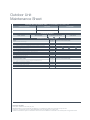
MELSMART Installation
Standards
MELSMART
TECHNICAL SERVICES
Contents
Section One - Air Conditioning
1.
Melsmart Technical Services
2.
Introduction AC & R
3.
F Gas
4.
Refrigeration Pipework
5.
Insulation
6.
Electrical Work
7.
Drain Pipework
8.
Ductwork, Grilles and Diffusers
9.
Commissioning Standards - Split Systems
10. Commissioning Standards - VRF Systems
11. Maintenance
Section Two - Heating
1.
Applied Products
2.
The Importance of Design, Installation & Commissioning
3.
Pipework & Fittings
4.
Insulation
5.
Electrical Work
6.
Drain Pipework
7.
Testing & Commissioning Standards
8.
Maintenance
1. Melsmart Technical Services
Mitsubishi Electric as ever is taking an industry lead to even further
improving the way it does business. We are committed to quality both in the equipment we supply and the services that are provided
to our customers. That is why Mitsubishi Electric is committed to
demonstrate its expertise and competence in key areas such as
Installation, Commissioning, Maintenance, Health and Safety,
Corporate Social Responsibility and Refrigerant Handling.
These standards incorporate best practice methods gathered from
our own experience with our products, but also from renowned third
parties such as HVCA RAC/80.
The Standards incorporate:
Installation
Commissioning
Maintenance
2. Introduction AC & R
The fixing of all air conditioning equipment, installation of all refrigerant pipework and full commissioning
shall be performed by us.
We may use specialist Sub-Contractors that meets the standards and are already fully trained by
Mitsubishi Electric.
Full access shall be afforded to site during the installation stage of the project to allow us to verify that
installation methods are fully in accordance with Mitsubishi Electric’s requirements and that the equipment
warranties will not be invalidated. All works including labour, materials, plant, tools and equipment will
comply with BS EN378:2008. We always pride ourselves in assuring that good practices are always
adhered to from start to finish on any installation and we will always consider the following but not limited
to these:
2.1
Retain the responsibility to advise of any aspects which, based upon experience would appear to
be inappropriate and or likely to lead to operational problems.
2.2
Health & Safety at Work Act 1974, and all other relevant attendant legislation, particularly the
management of Health & Safety at Work Regulations 1992, Personal Protective Equipment at
Work Regulation 1992 and the Construction, Design and Management (CDM) Regulation 1994.
2.3
Ensure that all personnel are in possession of the appropriate personal protective equipment
complying with the Personal Protective Equipment Regulations 1992.
2.4
Ensure that all personnel are fully competent in the work they are tasked to perform and any claim
to stated qualifications are valid.
2.5
Ensure that all personnel are instructed to comply with the prevailing site rules/directions.
2.6
Must use calibrated and regularly checked tools. Electrical tools will be calibrated and checked
annually.
2.7
Upon completion of the works ensure that all debris is removed and the site is left clean and tidy to
the satisfaction of the Customer.
3. F Gas
Summary of Key Obligations under the EC F Gas Regulation.
Many organisations use RAC systems with HFC refrigerants, which are F Gases. If such refrigerants are
used, the company must ensure that it meets the requirements in EC Regulation 842/2006 on certain
fluorinated greenhouse gases (F Gases) and the GB Fluorinated Greens House Gases Regulations 2009
(Statutory Instrument No 261).
In summary, the EC F Gas Regulation requires:
EC F Gas Regulation Requirements
Leak Checks
Regular checks for leakage; use of automatic leak detection on large systems.
Recovery
Refrigerant recovery during plant service and maintenance and at end of life.
Records
Good records kept for equipment containing 3 kg or more of F Gases.
Training and
Certification
Use of personnel with appropriate qualifications.
Company Certification required for all companies employing personnel to
undertake work on equipment containing or designed to contain F Gases
(includes sole traders).
Companies taking delivery of F Gases need to employ personnel with appropriate
qualifications if undertaking leak checking, gas recovery, plant installation,
maintenance or servicing.
Other
Certain other actions including labelling of new equipment.
4. Refrigeration Pipework
Supply and installation of all interconnecting refrigeration pipework will be carried out by us in accordance
with Section 4, Part 1, of the “Safety Code for Refrigerating Systems Utilising HFC’s published by the
Institute of Refrigeration and to BS EN 378:2008 Specification and Mitsubishi Electric Living Environmental
Systems design and installation instructions. All pipework must be suitable for R410A. Longest possible
lengths of copper pipe should be utilised to minimise joints on site.
Furthermore all of the following points should be adhered to.
4.1
All copper pipe up to 1 1/8” (28 mm) outside diameter (O/D) shall be fabricated from refrigerant
quality tube to (BS 2871: Part 2) BS EN 1056, Table 2 – material designation C106. Tube shall
be fully annealed up to 7/8” (22 mm) outside diameter (O/D) only. Tube shall be delivered to site
internally degreased and shall be stored in clean dry conditions with ends sealed until required
for installation.
4.2
All due consideration and allowances shall be taken to keep pipework clean and dry during
the installation works. Ensuring all pipework unfinished ends are capped off at all times.
4.3
The number of joints, bends and sets are to be kept to a minimum. Butt joints will not be
accepted, properly swaged joints must be formed. Bends and sets are to be machine
pulled to an approved radius where possible.
4.4
Flared Joints must only be used when connecting to the manufacturer’s equipment.
Brazing shall be carried out in accordance with British Refrigeration Association Specification
for brazing and BS 14324. Brazing rods shall be cadmium free and conform to BS 1845.
At all times, when brazing, a small amount of dry nitrogen must be purged through the pipe
to prevent oxidation and scaling internally. Any component susceptible to heat during the brazing
process that may be damaged must be protected. Soft solder shall never be used for jointing of
refrigeration pipework.
4.6
All completed R410A systems will be strength and leak tested with dry nitrogen as per the
Mitsubishi Electric City Multi Commissioning Log Book method statements as below and
BS EN 378:2008. If the system is found to be leak free. The final pressure readings for both
strength and leak testing are to be witnessed and entered into the Mitsubishi Electric
Commissioning Log Book (Method Statement 1).
City Multi Commissioning Log Book Method Statements
Design Pressures
≥ 1.0 ps
System strength pressure test
1.1 to 1.3 x ps
Tightness test pressure assemblies
≥ 1.0 x ps
Safety switch devices for limiting the pressure for systems with relief device, setting
≥ 0.9 x ps
Safety switch devices for limiting the pressure for systems without relief device, setting
≥ 1.0 ps
Pressure relief device, setting
≥ 1.0 ps
Pressure relief valve achieves the required flow at 1.1 ps
≥ 1.1 ps
Good Practice; 5 Steps Strength and Leak Test.
1)
3 bar (N2) Minimum of 3 minutes.
2)
15 bar (N2) Minimum of 3 minutes.
3)
32 bar (N2) Minimum of 15 minutes.
4)
41.5 bar (N2) Strength test for a period of time that is acceptable to show any signs of deformation
to the pipework.
5)
33 bar (N2) After step 4, drop pressure to 33 bar for final leak test for minimum 24 hours.
Pressure testing signage will be clearly visible on site during testing periods.
4.7
On completion of strength/leak testing an evacuation is to be carried out to 2mm Hg (2 Torr).
This will eliminate the risk of any moisture being present within the pipework installation. It is
recommended that a triple evacuation process be carried as below and as per the method
statement in the City Multi Commissioning Logbook (Method Statement 2). This should then
be followed by a pressure rise test.
6 Steps Evacuation.
1) Evacuate the system to 10 Torr from both service valves. System manifold gauges
“must not” be used to measure a vacuum. A Torr gauge must be used at all times.
2) Break the vacuum with OFN (N2) into “suction” service valve to 1 bar.
3) Evacuate to 5 Torr from “discharge valve”.
4) Repeat step 2.
5) Evacuate to lowest pressure vacuum pump will achieve (2 Torr for 1 hour minimum).
6) Pressure rise test to be carried for a minimum of 30 minutes.
5. Insulation
Thermal insulating material used within any building shall, when tested in accordance with BS 476 Part 4:
1970, be classified as non-combustible also free from substances which in the event of a fire would
generate appreciable quantities of smoke or toxic fumes. Insulating materials of “Class O” rating, as
defined by the Building Regulations.
5.1
Thermal insulation will be fitted to all the pipe work installations detailed herein. All materials used
will be ‘non-combustible’ “Class O”. All insulation materials, adhesives and finishes, will be suitable
in all respects for continuous use without degradation throughout the range of operating
temperatures and within the environment indicated.
5.2
The materials and method of installation will comply with all relevant British Standards Codes of
Practice.
5.3
The material will consist of flexible CFC free, elastomeric black foam with a closed cell structure.
The outer surface of the foam will be an inherent vapour barrier.
In all cases where pipes pass through fire compartment walls, fire resistant and non-flammable
insulation/foam will be packed between the pipe sleeve and the pipe. All insulation will be
supplied at the thickness specified in HVCA standards.
6. Electrical Work
We will include for the design and installation (unless otherwise specified) including connecting all items of
mechanical equipment. We will provide and install all wiring, cables, conduit, trunking, cable trays,
termination points, local means of isolation, control wiring etc., to mechanical plant items to ensure that
all items of equipment and controls fully function in accordance with manufacturers recommendations
and the current IEE Wiring Regulations, CIBSE Codes of Practice, British Standards and UK Building
Regulations.
6.1
All electrical cables used for power distribution will comply with current IEE Wiring Regulations.
All cables used for data/control must be greater than 1.25 mm2 2-core screened.
6.2
Appropriate glands will be fitted to each item of equipment in accordance with environmental
conditions.
6.3
The whole installation will be in full accordance with the current I.E.E. Wiring Regulations in every
respect with particular attention to clipping, earthing of equipment, glanding off final connections
and isolating.
6.4
Earth bonds on refrigeration, cold water and drainage pipework to be applied, throughout.
6.5
Equi-potential bonding between exposed conductive parts and extraneous conductive parts at
the same potential, to be applied throughout.
6.6
On completion the installation should be tested in accordance with the requirements of Inspection
and Testing section of the current I.E.E. Wiring Regulations. Inspection shall include physical
check that all equipment has been securely fixed and that all electrical connections are
mechanically sound.
6.7
Where necessary to prevent damage to components of equipment, the equipment shall be
disconnected for the duration of the relevant tests.
6.8
Heat resisting cable should be used in all locations where wiring is subjected to ambient
temperatures in excess of 40°C (104°F).
6.9
A suitable means of isolating the electricity supply shall be fitted adjacent to and within reach and
sight of the equipment with over current protections.
6.10 When running interconnecting control wiring it is essential to avoid the risk of electronic control
signals being corrupted. Care should therefore be taken to avoid running control cables too close
to power cables.
7. Drain Pipework
A condensate line shall be installed to each fan coil unit. This will be installed (and insulated with copper
or any other appropriate metallic pipe) all as per the standard specification. Minimum size of condensate
pipes to be 22mm copper or plastic, insulated and pumped or by gravity from each fan coil/cassette,
drains to run 1:80 min falls as indicated on drawings.
7.1
Pipework will be adequately supported in such a manner as to permit free movement due to
expansion and contraction.
7.2
Pipework should be graded to fall throughout and run to waste and should be accessible for cleaning.
7.3
On completion, a leak and function test must be carried out.
7.4
If Outdoor Units are installed inside a condensate drain tray will be fitted to collect and remove
any condensate produced.
7.5
Gravity drains will be installed whenever possible.
8. Ductwork, Grilles and Diffusers
Unless specified otherwise all sheet metal ductwork will be manufactured and installed in accordance
with HVCA specification DW/144:1998. Ductwork systems will be designed to give a maximum air
velocity of 5 and 8 m/s on main ducts and between 4 and 6m/s on branch ducts. The ductwork system
design is to take into account the equipment’s characteristics in terms of static pressure generation and
acoustic properties and suitable means of regulation to be incorporated.
8.1
Ductwork shall be manufactured using hot dipped galvanised steel sheeting to BS EN 10327:2004.
8.2
Bends and fittings for rectangular ductwork will be of square type with internal turning vanes.
8.3
Circular ductwork will generally be of the “spirally wound” type utilising standard sizes as specified
in DW/144.
8.4
Bends in circular ductwork shall be a minimum of 0.5D throat radius.
8.5
Branches onto main ducts will be by “shoe” type connections with a 45° leading edge.
8.6
All ductwork will be adequately supported from the building structure using one of the methods
approved by DW/144:1998 appropriate to the size of duct.
8.7
All ductwork systems will be fitted with sufficient volume control dampers to enable system
balancing. To prevent noise regeneration final trimming to 10% only of airflow’s to be carried out
using the opposed blade dampers fitted to terminal devices.
8.8
Fire dampers are to be fitted to ductwork passing through designated fire barriers, these dampers
to be fitted with HEVAC installation frames where passing through structural walls.
8.9
Flexible ducting shall be used to form the final connection to the air terminal device. The maximum
length not to exceed 1.5 metres and incorporate a change in direction of not greater than 90°.
8.10 Flexible ducting will be manufactured from aluminium/polyester/aluminium laminate enclosing a
high tensile steel wire helix. Where required flexible ducting will be of the insulated type with an
outer jacket of reinforced aluminium laminate giving a class ‘O’ rating.
8.11 Joints between flexible and rigid ductwork to be secured by worm drive clip with the rigid ductwork
spigot incorporating a ‘swaged’ end.
8.12 Insulation will be applied to the following ductwork systems;
Fresh air intake ductwork.
Heat recovery ventilation return air ducts passing through unheated spaces.
All conditioned air ductwork (unless an architectural feature and adequate control
is provided to prevent condensation forming on the ductwork.
8.13 Insulation shall be either Rockwool ductwrap minimum 25mm thick, or phenolic foam,
with re-enforced aluminium foil vapour barrier giving a class ‘O’ rated finish and a thermal
conductivity of 0.018W/M/ºK. The insulation is to be applied in accordance with the
manufacturer’s recommendations. All joints to be securely taped with 75mm wide
self-adhesive aluminium tape and further secured with wire loops at 1.0m intervals.
8.14 All ductwork will be fitted with identification bands and directional arrows in accordance with
BS1710:1984.
8.15 Air terminal devices will be selected to provide the required air flows/throws for the system design,
are to provide a draught free environment in all operating conditions and take into account the
acoustic requirements of the installation. Generally terminal neck velocities will not exceed 3.5m/s
to prevent noise regeneration.
9. Commissioning Standards - Split Systems
Pre-commissioning.
9.1
A marked up scale site drawing showing all Mitsubishi Electric units and refrigeration pipework,
address settings (for units and remote controllers) and model/serial numbers will be produced.
9.2
Fan coil units, Outdoor Units addressing and screened wiring (greater than 1.25mm2)
as per the Mitsubishi specification (refer to current data book).
9.3
All control wiring; remote controllers and A-M net adaptors (if fitted) will be complete and connected.
9.4
Before the Power Supply to Outdoor Unit is turned on, the mains wiring must be checked phase
to neutral, neutral to earth. Once this is complete the mains isolator can be switched on to allow
the crankcase heater to warm up the oil (minimum 24 hours).
9.5
All power supply wiring to Indoor Units must be complete, tested and left switched on at indoor
unit isolators.
9.6
Pressure test system refrigerant pipework must be completed as per F Gas regulations and section 4.6.
9.7
Evacuation of the system refrigerant pipework will be completed as per section 4.7.
9.8
Condensate pipework will be completed and tested.
9.9
Totals lengths of liquid line pipework installed, will be confirmed by our Installation Engineers and
marked on drawings for additional refrigerant charge calculation.
9.10 Sufficient supply of refrigerant R410A in dumpy cylinders will be on site adjacent to the Outdoor
Units ready for use.
9.11 Now charge refrigerant into pipework based upon the additional refrigerant charge calculation.
9.12 Outdoor Unit service valves will now be opened.
Commissioning Split Systems.
9.13 Connect A-Control Service Tool (Part No PAC-SK52ST(G)) and check system connect information.
9.14 Start up the system and check each Indoor Unit one by one in cooling mode to confirm correct
operation superheat and pipe temperatures.
9.15 Then change over all Indoor units to heating mode and check operation, sub-cooling and pipe
temperatures.
9.16 Set up and configure all controllers/time clocks/centralised controllers.
9.17 Check operation of any accessory interlocks i.e. time clocks, centralised controllers etc.
9.18 Carry out airflow and static pressure drops on any units connected to ductwork.
9.19 Check operation of all condensate pumps if fitted.
9.20 Monitor operation for at least 1 hour. Observe and record all data.
9.21 Complete Commissioning Log Book.
9.22 Record all refrigerant usage in total compliance with F Gas.
10. Commissioning Standards
- VRF Systems
Pre-commissioning.
The following items must be checked prior to any systems being switched on.
10.13 A marked up scale site drawing showing all Mitsubishi Electric units and refrigeration pipework,
address settings (for units and remote controllers and BC branch connections) and model/serial
numbers will be produced.
10.14 City Multi fan coil units, BC Boxes, Outdoor Units addressing and screened wiring (greater than
1.25mm2) as per the Mitsubishi specification (refer to current data book).
10.15 All control wiring and remote controllers will be complete and connected but final connection
to TB3 & TB7 left disconnected.
10.16 Before the Power Supply to outdoor unit is turned on, the mains wiring must be checked
phase to neutral, neutral to earth. Once this is complete the mains isolator can be switched
on to allow the crankcase heater to warm up the oil (minimum 24 hours).
10.17 All power supply wiring to indoor units (BC controllers if R2 system) will be complete, tested
and left switched on at indoor unit isolators.
10.18 Pressure test system refrigerant pipework will be completed as per F Gas regulations and section 4.6.
10.19 Evacuation of the system refrigerant pipework will be completed as per section 4.7.
10.20 Condensate pipework will be completed and tested.
10.21 Totals lengths of liquid line pipework installed, will be confirmed by installation Engineers and
marked on drawings for additional refrigerant charge calculation.
10.22 Sufficient supply of refrigerant R410A in dumpy cylinders will be on site adjacent to the Outdoor
Units ready for use.
10.23 Now charge refrigerant into pipework based upon the additional refrigerant charge calculation.
10.24 Outdoor Unit service valves will now be opened.
Commissioning.
10.25 Connect monitor tool and check system connect information is correct i.e. Outdoor Unit, BC port,
Indoor Unit and Remote controller addresses.
10.26 Start up the system and run each Indoor Unit one by one in cooling mode to confirm correct
operation superheat and pipe temperatures.
10.27 Set up and configure all controllers/time clocks/centralised controllers.
10.28 Then change over all Indoor units to heating mode and check operation, sub-cooling and pipe temperatures.
10.29 Check operation of any accessory interlocks i.e. time clocks, centralised controllers etc.
10.30 Check operation of all condensate pumps if fitted.
10.31 Monitor operation for at least 1 hour. Observe and save all data.
10.32 Complete Commissioning Log Book.
10.33 Record all refrigerant usage in total compliance with F Gas.
11. Maintenance
11.1 The following tables outline the periodic maintenance frequencies and maintenance tasks
recommended by Mitsubishi Electric. Frequencies may increase depending on the equipment’s
geographical location and environment. A minimum of 2 visits per annum is required.
11.2 Filter cleaning to be carried out a minimum of 2 times per annum. This may increase depending
on the equipment’s environment.
Important Note.
Summary of F Gas Key Obligations under the EC Ozone Regulation.
If an organisation is using HCFC refrigerants (such as R22) it must also comply with the requirements of
EC Regulation 1005/2009 (this regulation came into force on January 2010 and replaced the old Ozone
Regulation EC2017/2000 which has now been revoked) and GB Statutory Instruments 2011 No. 1043
and 2009 No. 216.
In summary, the EC Ozone Regulation requires:
EC Ozone Regulation Requirements
Phase-Out
Phase-out of HCFC usage between 2010 (virgin fluid) and 2015
(Recycled/reclaimed fluid).
Leak Checks
Annual leakage checks for equipment containing 3 kg or more of refrigerant.
Recovery
Refrigerant recovery during plant servicing and maintenance and at end of life.
Records
Good records kept for equipment containing 3 kg or more of a HCFC.
Training
Use of personnel with prescribed qualifications.
Outdoor Unit
Maintenance Sheet
OUTDOOR UNIT MAINTENANCE SHEET - Complete ONE form per Outdoor Unit
CONTRACTOR NAME
SITE NAME
SITE NUMBER
ENGINEER NAME
DATE OF VISIT
OUTDOOR UNIT DETAILS
MODEL NUMBER
SERIAL NUMBER
COMPRESSOR RUN HOURS
No.1
No.2
AREA SERVED
No.3
MAINTENANCE TASKS - OUTDOOR UNIT 1
TASKS
FREQUENCY
Inspect and clean Heat Exchanger
Every Visit
Check for Visible Signs Refrigerant Leaks
Every Visit
Check integrity of Pipework and Lagging
Every Visit
Check all Electrical Connections including Mains Isolator and tighten as necessary
Every Visit
Check Unit Operation Voltage and record
Every Visit
Check Unit Operation Current and record
Every Visit
Check Compressor Run Hours And Record * ( All Compressors )
Every Visit
Check Discharge Temperature And Record * (All Compressors )
Every Visit
Check Suction Temperature And Record *
Every Visit
Check Discharge Pressure And Record * (All Compressors )
Every Visit
Check Suction Pressure And Record *
Every Visit
Check Operation of Crankcase Heater ( All Compressors )
L1
to N
L2
to N
L3
to N
N to
Earth
Every Visit
WR2/WY ADDITIONAL TASKS
FREQUENCY
Check Integrity of Pipework and Lagging (Refrigerant and Water Systems)
TICK BOX OR RECORD READING
Every Visit
Check Water Flow Temperature and record
Every Visit
Check Flow Switch Operation and Record
Every Visit
Check and Clean Water System Strainers
Every Visit
Check Water Return Temperature and record
TICK BOX OR RECORD READING
Every Visit
ADDITIONAL NOTES AND TASKS CARRIED OUT
*Obtained by the use of Dipswitch SW1
Frequency of Visits:
Every Visit - Minimum of 2 visits per year.
Mitsubishi Electric recommends that the frequency of maintenance visits be no less than two per annum.
Frequency of maintenance may increase dependant upon the equipment's environment.
Failure to maintain the system to the above minimum recommendations could result in the warranty becoming null and void
Indoor Unit
Maintenance Sheet
INDOOR UNIT MAINTENANCE SHEET - Complete ONE form per Indoor Unit
CONTRACTOR NAME
SITE NAME
ENGINEER NAME
SITE NUMBER
DATE OF VISIT
INDOOR UNIT DETAILS
MODEL NUMBER
SERIAL NUMBER
AREA SERVED
MAINTENANCE TASKS - INDOOR UNIT 1
TASKS
FREQUENCY
Clean Air Handling Unit Filters
Every Visit
Check Evaporater Coil for Dirt and Clean as Necessary
Every Visit
Check Drip Tray for Dirt and Debris and Test Condensate Pump for Correct Operation (if fitted)
Every Visit
Check Fan Motor and Fan Blade Visual Inspection
Every Visit
Check Air On Coil Temperature in Cooling
Every Visit
Check Air Off Coil Temperature in Cooling
Every Visit
Check Air On Coil Temperature in Heating
Every Visit
Check Air Off Coil Temperature in Heating
Every Visit
Check Controls Operation
Every Visit
ADDITIONAL NOTES AND TASKS CARRIED OUT
Frequency of Visits:
Every Visit - Minimum of 4 visits per year.
Mitsubishi Electric recommends that the frequency of maintenance visits be no less than four per annum.
Frequency of maintenance may increase dependant upon the equipment's environment.
Failure to maintain the system to the above minimum recommendations could result in the warranty becoming null and void
1. Applied Products
Heat pumps are becoming increasingly more popular and now are considered as a viable
alternative to traditional combustion-based heating plant due to the reduced running costs
and carbon emissions.
Heat Pumps are devices for upgrading heat energy from naturally occurring low temperature heat
sources into useful high temperature heat to provide a renewable source of heat. This technology
is already well known in the air conditioning sector and has proved very efficient when used for both
cooling and heating applications.
The operational characteristics of a heat pump are totally different to those of a conventional
combustion-based heating boiler. With a conventional boiler, one kilowatt of energy ‘in’ gives less
than one kilowatt of heat to the building. With a typical electrically driven heat pump, one kilowatt
of energy ‘in’ can generate a heat output in excess of 3 kilowatts. This ratio is known as the
Coefficient of Performance (COP).
The important characteristic of a heat pump system is that the amount of heat that can be transferred
is greater than the energy required to drive the cycle, therefore, the amount of energy used is much
less in a heat pump, significantly lowering operating costs and carbon emissions.
2. The Importance of Design, Installation
& Commissioning
2.1
Effective operation of a heat pump system depends on satisfactory design, installation and
commissioning. It is important that practical commissioning requirements are fully considered
by the designer at the conceptual stage, i.e. that the system can be regulated and there are
appropriately located Valves and flow measurement devices to enable the commissioning
specialist to achieve this. The design must provide a realistic commissioning specification
so that satisfactory commissioning is assured and the systems perform as intended.
Early discussions with the commissioning specialist will assist the designer to achieve this.
2.2
Mitsubishi will provide a Technical Submission document for each Air to Water Heat Pump system
based upon the parameters agreed with the designer/contractor which will clearly identify the
selection principles and set out the performance criteria under which the equipment will perform.
2.3
Systems should be designed to achieve as low as possible life cycle costs in terms of installation,
maintenance and running costs.
2.3.1. Factors affecting installation costs would be selection of suitable materials and components
which are adequate for the application.
2.3.2. Factors affecting running costs would be flow & return temperatures and pumping power.
2.4
For heat pump systems to yield low running costs, the system should be designed such that
the lowest possible temperature difference exists between the mean water temperature and the
ambient condition together with suitably sized circulating pumps that are selected at their most
efficient operating condition.
2.5
Pumping power is influenced by system pressure drop characteristics which are directly related
to pipework sizes. Pipework should be sized in accordance with recommended CIBSE & BSRIA
guidelines in terms of fluid velocity and pressure drops characteristics (see below).
Pipework Dia
Steel
Copper
50mm and below
0.75 - 1.5m/s
Up to 1.0m/s
Above 50mm
1.25 - 3.0m/s
Up to 1.5m/s
Minimum pressure drop per meter of pipework (Steel & Copper) = 200Pa/m
Maximum pressure drop per meter of pipework (Steel & Copper) = 300Pa/m
2.5.1. Incorrectly sized pipework resulting in excessive fluid velocities and system pressure drops
leads to increased pumping power requirements which in consequence results in poor overall
system efficiency levels which contribute to excessive carbon emissions.
2.6
The system design must follow the principles of maximisation of Heat Pump efficiency;
2.6.1. Heat Pump sized correctly for the specific site taking due account of the building heat load and
the requirements of any attached systems.
2.6.2. Reduce the heating capacity of the heat pump system by avoiding additional heat load due
to intermittent heating.
2.6.3. Design the heat pump system to achieve highest possible seasonal efficiency levels. The seasonal
efficiency improves by decreasing the temperature difference between the mean water
temperature and ambient condition.
2.6.4. The heat pump system should be designed and controlled to avoid excessive start-up cycles.
2.6.5. Heating system should be designed to minimise the flow temperature required by the Heat Pump.
2.7
System design should take account of system water content such that the minimum water
volume for the heat pump boiler is achieved taking into account the application such that system
cycling at part load is minimised.
3. Pipework & Fittings
The Contractor shall provide and install all pipes, pump sets, commissioning sets, valves etc, to
mechanical plant items to ensure that all items of equipment and controls fully function in accordance
with manufacturer’s recommendations and the current CIBSE Codes of Practice, British Standards and
UK Building Regulations.
3.1
All pipework must be appropriately sized based on flow rates to provide a reasonable pressure
drop for the system.
3.2
Maximum and minimum water velocities should be adopted to minimise dirt and air settlement
in horizontal pipes at low velocities, or noise at high velocities.
3.3
A differential pressure switch must be connected to each Mitsubishi Electric Heat Pump to isolate
and protect the unit in the event of flow failure or blockage.
3.4
A mechanical strainer must be installed on the inlet pipework of the Heat Pump. The strainer
must be installed in the correct orientation to allow proper cleaning and emptying of the strainer.
3.5
Suitable provision for measurement of differential pressure should be provided at inlet & outlet
connections across all items of equipment, circulating pumps and strainers.
3.6
A flushing bypass must be provided to each Mitsubishi Electric Heat Pump unit complete
with isolating valves to provide complete isolation of the Heat Pump whilst undertaking
pre-commissioning flushing activities.
3.7
A fixed orifice double regulating valve (commissioning set) must be provided for each Heat Pump
to balance the system and to allow flow rate to be determined during commissioning. Regulating
valves should be selected based on the flow rate and pressure loss requirements of the branches
in which they are installed. It should not be assumed that all valves will be line size.
3.8
Provision to isolate the heat pump using isolating valves for service and maintenance should be
provided.
3.9
Installation pipework should be installed in accordance with manufacturer’s recommendations,
CIBSE Guidelines, BSRIA recommendations and all current relevant British Standards.
3.9.1. Pipework should be either; Copper, Steel or alternatively plastic to the relevant British Standard.
3.9.2. Pipework should be arranged to accommodate pipe movement caused by thermal expansion.
Generally allow the flexure at changes in direction and allow for movement at branch connections.
3.9.3. Where possible provision for movement due to thermal expansion and contraction shall be
made by natural changes in direction. Anchors and guides shall be positioned to contain all
movement and resist the maximum loads imposed with anchors and guides being located at
points which prevent excess stresses on the pipework joints and equipment connections.
3.9.4. Arrange all exposed pipe runs to present neat appearance, parallel with other pipe or service
runs and building structure, subject to gradients for draining and venting.
3.9.5.
Space pipe runs in relation to one another, other services runs and building structure, allow
for specified thickness of thermal insulation and ensure adequate space for access to pipe
joints etc.
3.9.6.
Use eccentric type reductions and enlargements on horizontal pipe runs to allow draining
and venting.
3.9.7.
Enclose pipes passing through building elements, (walls, floors, partitions, etc.) concentrically
within purpose made sleeves. Fit masking plates where visible pipes pass through building
elements, including false ceilings of occupied rooms.
3.9.8.
Make final connections to equipment in accordance with manufacturer's instructions and as
indicated. Provide flanges or unions to enable removal of equipment with minimum disassembly
of pipework.
3.9.9.
Take appropriate means to prevent galvanic action where dissimilar metals are connected together.
3.9.10.
Arrange pipework, valves, drains, air vents, demountable joints, supports, etc, for convenient
routine maintenance and renewals. Ensure that the location of pipelines, wiring and wireways
does not hinder or prevent the maintenance or removal of removable equipment such as
filters etc.
3.9.11.
Automatic air vents should be installed at high points of the pipework installation and drain
cocks at all low points.
3.9.12.
Arrange pipework supports so that no undue strain is imposed upon pipes, with supports
spaced at appropriate centres suitable for the application.
3.9.13.
Provide all runs with a regularly spaced pattern of demountable joints in the form of unions,
flanges, etc., and also at items of equipment to facilitate disconnection.
3.9.14.
Provide temperature and altitude gauges as necessary to indicate system operating
temperature and pressures across plant items and sub-circuits.
3.10
Hot water cylinders should be manufactured and installed in accordance with the relevant
British Standards and The Water Supply (water fittings) Regulations 1999.
3.10.1.
Unvented units should be complete with “unvented kits’’ and pressure regulating valve
to comply with Building Regulations safety requirements within Approved Document G3.
Units shall comply with BS EN 12897.
3.10.2.
Cylinders should be complete with manhole (where applicable), connections to BS 15661:2002, drain cock, purpose made feet or support frames, protective isolation material to
prevent electrolytic action where applicable and thermal insulation.
3.11
An air/dirt separator must be provided on the primary circuit. It should be located on the Low
pressure (suction of the primary circulating pump) side of the system and the high temperature
(flow) side of the Heat pump(s).
3.11.1.
To obtain correct performance of the units the inlet water velocity is critical and the air/dirt
separator must be sized in accordance with the manufacturers recommendations and be
capable of being fully isolated.
3.11.2.
Air/dirt separators should be manufactured from a vertical mild steel housing, fitted with
non-clogging helicoidal separation tubes and mesh/packing manufactured from copper tube,
stainless steel or other proprietary material to create the correct environment at the top of the
unit to deaerate efficiently by separating the smallest microbubbles. The unit should provide an
air release mechanism comprising a solid polypropylene float and self-closing air release valve.
3.11.3.
All Deareation & Dirt separation equipment must be compliant with the Pressure Equipment
Reguations 1999, and be manufactured and supplied by companies complying with the
requirements of “Lloyds register quality assurance ISO9001”.
3.12
Circulating pumps should be manufactured and tested in accordance with the appropriate
British Standards, in particular BS EN 809, BS EN 60335-2-41 & BS EN 60335-2-51
where applicable.
3.12.1.
Pumps should be selected at or near most efficient part of performance curve for the duty
required. Whenever possible select single stage centrifugal pumps to achieve minimum pump
efficiency (after correcting for pump head) equal to or better than defined by the upper efficiency
line in figs 3 – 6 of the “European Guide to Pump Efficiency for Single Stage Centrifugal Pumps”
as published by Europump 2003. (ie “Optimum efficiency selections).
3.12.2.
A pump duty should be selected to deliver the maximum design flow rate against the estimated
pressure drop around the hydraulic circuit, and should include the following commissioning
allowances: Flow rate + 110% and Head + 115%. These allowances are in addition to the
calculated design duty to allow for system regulation and additional fittings unforeseen at the
design stage.
3.12.3.
The pump operating point must be located within the pump manufactures recommended
operating range for the particular pump selected.
3.12.4.
The pump should operate within the stable region at the design load.
3.12.5.
Flexible connections must be installed on each pump at both the suction and delivery side of
every pump.
3.12.6.
The pump installation should provide a method of isolation for the replacement of equipment
complete with isolation valves.
3.12.7.
Pumps should be installed in accordance with the manufactures recommendations; glandless
pumps should not be installed with the shaft in the vertical and in-line pumps should ensure
that the motor is positioned as the manufacturer’s instructions.
3.12.8.
Pumps should be supported independently from connecting pipework to ensure no load
is transmitted from the pipework to the pump casing on pump suction and discharge.
3.12.9.
Pumps should be aligned to prevent undue restraint and thrust on the interconnecting pipework.
3.12.10. Pumps should be located within the system with adequate space around it for service
and maintenance.
3.13
A pressurisation unit and expansion vessel, correctly sized for the primary system, should be
installed on the return side of the heat pump complete with isolation valves for replacement
of equipment.
3.13.1.
Pressure vessels for sealed hot water systems must be installed in accordance with the relevant
current British Standards, in particular BS EN 13831 & BS 7074 Part 1 (Domestic heating and
hot water supply) or Part 2 (Low and medium temperature hot water heating systems) as
applicable and BS EN 12828.
3.14
Chemical treatment of the heating system should be achieved by installation of a suitably
selected Dosing Pot.
3.14.1.
Provide Dosing Pot with a tundish for filling; separate air vent with discharge tube; drain and
isolating valves.
3.14.2.
Fabricate from mild steel tube to BS EN 10255 or BS EN 10216 / 7 to suit maximum working
pressure of system.
4. Insulation
Thermal insulating material used within any building shall, when tested in accordance with BS 476 Part 4,
be classified as non-combustible also free from substances which in the event of a fire would generate
appreciable quantities of smoke or toxic fumes. Insulating materials of “Class O” rating, as defined by the
Building Regulations
4.1
Thermal insulation should be applied, as appropriate, to all the pipe work installations detailed
herein. All insulation materials, adhesives and finishes shall be in compliance with the relevant
British Standards and shall obtain a Class 'O' fire rating and shall not be flammable or support
combustion.
4.2
All insulation materials, adhesives and finishes, will be suitable in all respects for continuous use
without degradation throughout the range of operating temperatures and within the environment
indicated.
4.3
The materials and method of installation will comply with all relevant British Standards Codes of Practice.
4.4
The insulating material shall be:
4.4.1 Inherently proof against rotting, mould and fungal growth and attack by vermin.
4.4.2 Non-hygroscopic and in all respects be suitable for continuous use throughout the range
of operating temperatures and within the environment indicated.
4.4.3 Wholly compatible with the material it is insulating at the design working temperature and
environmental conditions.
4.4.4 Free from chemicals which may contribute to corrosion or degradation of the insulated
surface or finish.
4.4.5 Comply with the Health & Safety at Work Act and COSHH Regulations and be non
carcinogenic.
4.4.6 Asbestos Free.
4.4.7 Delivered to site fully dried out and housed in dry store until ready for use.
4.4.8 Ensure all thermal insulation materials for the use in building services are made using materials
with zero ozone depletion potential and a GWP of less than 5 (CFC, HCFC & HFC free).
4.5
In all cases where pipes pass through fire compartment walls, fire resistant and non-flammable
insulation/foam will be packed between the pipe sleeve and the pipe.
4.6
Insulation material finish must be suitable for its intended application and care should be taken
when applying the finish to ensure it complies with the relevant British Standard and Codes of
Practice. External insulation must be finished with a suitable weatherproof finish.
4.7
To ensure compliance with maximum permissible heat loss criteria, insulation thicknesses should
be calculated according to BS EN ISO 12241 and BS 5422 using standardised assumptions.
5. Electrical Work
The contractor shall include for the design and installation (unless otherwise specified) including
connecting all items of mechanical equipment. The Contractor shall provide and install all wiring,
cables, conduit, trunking, cable trays, termination points, local means of isolation, control wiring
etc, to mechanical plant items to ensure that all items of equipment and controls fully function in
accordance with manufacturers recommendations and the current IEE Wiring Regulations, CIBSE
Codes of Practice, British Standards and UK Building Regulations.
5.1
All electrical cables used for power distribution will comply with current IEE Wiring Regulations.
All cables used for data/control must be greater than 1.25 mm2 2-core screened.
5.2
Appropriate glands will be fitted to each item of equipment in accordance with environmental conditions.
5.3
The whole installation will be in full accordance with the current I.E.E. Wiring Regulations in every
respect with particular attention to clipping, earthing of equipment, glanding off final connections
and isolating.
5.4
Earth bonds on refrigeration, cold water and drainage pipework to be applied, throughout.
5.5
Equi-potential bonding between exposed conductive parts and extraneous conductive parts at the
same potential, to be applied throughout.
5.6
On completion the installation should be tested in accordance with the requirements of Inspection
and Testing section of the current I.E.E. Wiring Regulations. Inspection shall include physical
check that all equipment has been securely fixed and that all electrical connections are
mechanically sound.
5.7
Where necessary to prevent damage to components of equipment, the equipment shall be
disconnected for the duration of the relevant tests.
5.8
Heat resisting cable should be used in all locations where wiring is subjected to ambient
temperatures in excess of 40°C (104°F).
5.9
A suitable means of isolating the electricity supply shall be fitted adjacent to and within reach
and sight of the equipment with over current protections.
5.10 When running interconnecting control wiring it is essential to avoid the risk of electronic control
signals being corrupted. Care should therefore be taken to avoid running control cables too
close to power cables.
6. Drain Pipework
Where applicable, a condensate drain line shall be installed from each external air to water heat pump.
This shall be installed as per the general pipework specification. Minimum size of condensate pipes to
be 22mm copper or plastic.
6.1
Pipework will be adequately supported in such a manner as to permit free movement due to
expansion and contraction.
6.2
Pipework should be graded to 1:80 min fall throughout and run to waste and should be accessible
for cleaning.
6.3
On completion, a leak and function test must be carried out.
6.4
If air to water heat pump units are installed internally, a condensate drain tray must be fitted to
collect and remove any condensate produced.
6.5
Gravity drains will be installed whenever possible.
7. Testing & Commissioning Standards
Pre-Commissioning
Pre-commissioning of pipework systems is a necessary process to bring the system to a satisfactory
state for commissioning and on-going maintenance of water quality and should be carried out in
accordance with BSRIA Guide BG 29/2011 Pre-commissioning Cleaning of Pipework Systems and
CIBSE Commissioning Code W: 2010.
The system should be free from installation debris, dirt and excessive particle matter. Internal surfaces
should be free of millscale and appropriately treated to minimise on-going corrosion. Pipework, fittings
and equipment should be free from settled solids that could increase the risk of corrosion.
General
Undertake inspection and commissioning of the building services systems in accordance with The
Building Regulations Approved Documents L1 & L2 and relevant CIBSE / BSRIA commissioning codes.
Pipework pressure testing should comply with the procedures given in HVCA Guide to Good Practice
for Site Pressure Testing of Pipework (TR6 2006). Ensure safety precautions detailed in HSE Guidance
Note GS4 Safety in Pressure Testing are adopted.
All components that cannot withstand the test pressures should be isolated as near to the component
as possible.
Pre-commissioning CAHV Systems.
The following items must be checked prior to any systems being switched on.
7.1
A marked up scale site drawing showing all Mitsubishi Electric units, address settings for units
and model/serial numbers must be produced.
7.2
Outdoor Units addressing and screened wiring (greater than 1.25mm2) as per the Mitsubishi
specification (refer to current data book).
7.3
All control wiring and remote controller must be complete and connected but final connection
to RA - RB & MA - MB left disconnected.
7.4
Before the Power Supply to outdoor unit is turned on, the mains wiring must be checked phase
to neutral, neutral to earth. Once this is complete the mains isolator can be switched on to allow
the crankcase heater to warm up the oil (minimum 24 hours).
7.5
Condensate pipework must be completed and tested (If required).
7.6
Components fitted to the system as below;
1.
2.
3.
4.
5.
6.
7.
8.
Flow Isolating Valve fitted.
*Strainer fitted (Supplied by Mitsubishi Electric).
Differential Pressure Switch DPS or Flow Switch fitted.
Commissioning Set fitted.
Return Isolating Valve before pump fitted.
Pump fitted.
Return Isolating Valve after pump fitted.
Bypass/flushing loop and Isolating Valve fitted.
7.7
Water system filled and pressurised and minimum water volume achieved 360 litres per CAHV unit.
7.8
Glycol added to the system to required percentage.
7.9
Safety interlocks connected.
1. Water flow switch.
2. Water (DPS) differential pressure switch.
3. Pump interlock.
Commissioning CAHV Systems.
7.10 Connect monitor tool and check system connect information is correct.
7.11 Check minimum flow rate achieved 2.10 l/s per CAHV unit.
7.12 Safety interlocks operation checked.
1. Water flow switch.
2. Water (DPS) differential pressure switch.
3. Pump interlock.
7.13 Start up the system and run each CAHV Unit one by one to confirm correct operation.
7.14 Set up and configure all controllers/time clocks/centralised controllers.
7.15 Check operation of any accessory interlocks i.e. time clocks, centralised controllers etc.
7.16 Monitor operation for at least 1 hour. Observe and save all data.
7.17 Complete Commissioning Log Book.
Pre-commissioning CAW/PWFY Systems.
The following items must be checked prior to any systems being switched on.
7.18 A marked up scale site drawing showing all Mitsubishi Electric units, address settings for units
and model/serial numbers must be produced.
7.19 Outdoor Units addressing and screened wiring (greater than 1.25mm2) as per the Mitsubishi
specification (refer to current data book).
7.20 All control wiring and remote controller must be complete and connected but final connection to
TB3 & TB7 left disconnected.
7.21 Before the Power Supply to outdoor unit is turned on, the mains wiring must be checked phase to
neutral, neutral to earth. Once this is complete the mains isolator can be switched on to allow the
crankcase heater to warm up the oil (minimum 24 hours).
7.22 All power supply wiring to PWFY Units must be complete, tested and left switched on at indoor
unit isolators.
7.23 Pressure test and evacuation of system refrigerant pipework must be completed as per section
2.6 & 2.7 (in the AC&R section).
7.24 Condensate pipework must be completed and tested (If required).
7.25 Totals lengths of liquid line pipework installed, must be confirmed by installation Engineers and
marked on drawings for additional refrigerant charge calculation.
7.26 Sufficient supply of refrigerant R410A in dumpy cylinders must be on site adjacent to the
7.27 Outdoor Units ready for use.
7.28 Now charge refrigerant into pipework based upon the additional refrigerant charge calculation.
7.29 Outdoor Unit service valves must now be opened.
7.30 Components fitted to the system as below;
1. Differential Pressure Switch DPS or Flow Switch fitted. (Supplied by others)
2. Pump fitted.
3. Flow Isolating Valve after pump fitted.
7.31 Water system filled and pressurised and minimum water volume achieved:
340 litres per CAW 400
510 litres per CAW 600 Unit.
100 litres per PWFY 100 Unit
7.32 Glycol added to the system to required percentage.
7.33 Safety interlocks connected
1. Water flow switch.
2. Water (DPS) differential pressure switch.
3. Pump interlock.
Commissioning CAW/PWFY Systems.
7.34 Connect monitor tool and check system connect information is correct Outdoor Unit, PWFY Units
and Remote controller addresses.
7.35 Check optimum flow rate achieved:
0.77 l/s per PWFY 200 Unit.
0.42 l/s per PWFY 100 Unit.
7.36 Safety interlocks operation checked.
1. Water flow switch.
2. Water (DPS) differential pressure switch.
3. Pump interlock.
7.37 Start up the system and run each PWFY Unit one by one to confirm correct operation.
7.38 Set up and configure all controllers/time clocks/centralised controllers.
7.39 Run all units to heating mode and check operation, sub-cooling and pipe temperatures.
7.40 Check operation of any accessory interlocks i.e. time clocks, centralised controllers etc.
7.41 Monitor operation for at least 1 hour. Observe and save all data.
7.42 Complete Commissioning Log Book.
7.43 Record all refrigerant usage in total compliance with F Gas.
8. Maintenance
8.1
The following tables outline the periodic maintenance frequencies and maintenance tasks
recommended by Mitsubishi Electric. Frequencies may increase depending on the equipment’s
geographical location and environment. A minimum of 2 visits per annum is required.
Important Note.
Summary of F Gas Key Obligations under the EC Ozone Regulation.
If an organisation is using HCFC refrigerants (such as R22) it must also comply with the requirements of
EC Regulation 1005/2009 (this regulation came into force on January 2010 and replaced the old Ozone
Regulation EC2017/2000 which has now been revoked) and GB Statutory Instruments 2011 No. 1043
and 2009 No. 216.
In summary, the EC Ozone Regulation requires:
EC Ozone Regulation Requirements
Phase-Out
Phase-out of HCFC usage between 2010 (virgin fluid) and 2015
(Recycled/reclaimed fluid).
Leak Checks
Annual leakage checks for equipment containing 3 kg or more of refrigerant.
Recovery
Refrigerant recovery during plant servicing and maintenance and at end of life.
Records
Good records kept for equipment containing 3 kg or more of a HCFC.
Training
Use of personnel with prescribed qualifications.
Outdoor Unit
Maintenance Sheet
OUTDOOR UNIT MAINTENANCE SHEET - Complete ONE form per Outdoor Unit
CONTRACTOR NAME
SITE NAME
SITE NUMBER
ENGINEER NAME
DATE OF VISIT
OUTDOOR UNIT DETAILS
MODEL NUMBER
SERIAL NUMBER
COMPRESSOR RUN HOURS
No.1
No.2
AREA SERVED
No.3
MAINTENANCE TASKS - OUTDOOR UNIT 1
TASKS
FREQUENCY
Inspect and clean Heat Exchanger
Every Visit
Check for Visible Signs Refrigerant Leaks
Every Visit
Check integrity of Pipework and Lagging
Every Visit
Check all Electrical Connections including Mains Isolator and tighten as necessary
Every Visit
Check Unit Operation Voltage and record
Every Visit
Check Unit Operation Current and record
Every Visit
Check Compressor Run Hours And Record * ( All Compressors )
Every Visit
Check Discharge Temperature And Record * (All Compressors )
Every Visit
Check Suction Temperature And Record *
Every Visit
Check Discharge Pressure And Record * (All Compressors )
Every Visit
Check Suction Pressure And Record *
Every Visit
Check Operation of Crankcase Heater ( All Compressors )
Every Visit
WR2/WY ADDITIONAL TASKS
FREQUENCY
Check Integrity of Pipework and Lagging (Refrigerant and Water Systems)
L1
to N
L2
to N
L3
to N
N to
Earth
TICK BOX OR RECORD READING
Every Visit
Check Water Flow Temperature and record
Every Visit
Check Flow Switch Operation and Record
Every Visit
Check and Clean Water System Strainers
Every Visit
Check Water Return Temperature and record
TICK BOX OR RECORD READING
Every Visit
ADDITIONAL NOTES AND TASKS CARRIED OUT
*Obtained by the use of Dipswitch SW1
Frequency of Visits:
Every Visit - Minimum of 2 visits per year.
Mitsubishi Electric recommends that the frequency of maintenance visits be no less than two per annum.
Frequency of maintenance may increase dependant upon the equipment's environment.
Failure to maintain the system to the above minimum recommendations could result in the warranty becoming null and void
Indoor Unit
Maintenance Sheet
INDOOR UNIT MAINTENANCE SHEET - Complete ONE form per Indoor Unit
CONTRACTOR NAME
SITE NAME
ENGINEER NAME
SITE NUMBER
DATE OF VISIT
INDOOR UNIT DETAILS
MODEL NUMBER
SERIAL NUMBER
AREA SERVED
MAINTENANCE TASKS - INDOOR UNIT 1
TASKS
FREQUENCY
Clean Air Handling Unit Filters
Every Visit
Check Evaporater Coil for Dirt and Clean as Necessary
Every Visit
Check Drip Tray for Dirt and Debris and Test Condensate Pump for Correct Operation (if fitted)
Every Visit
Check Fan Motor and Fan Blade Visual Inspection
Every Visit
Check Air On Coil Temperature in Heating
Every Visit
Check Air Off Coil Temperature in Heating
Every Visit
Check Controls Operation
Every Visit
ADDITIONAL NOTES AND TASKS CARRIED OUT
Frequency of Visits:
Every Visit - Minimum of 4 visits per year.
Mitsubishi Electric recommends that the frequency of maintenance visits be no less than four per annum.
Frequency of maintenance may increase dependant upon the equipment's environment.
Failure to maintain the system to the above minimum recommendations could result in the warranty becoming null and void
Commercial Heating
CAHV Maintenance Sheet
COMMERCIAL HEATING CAHV MAINTENANCE SHEET - Complete ONE form per Outdoor Unit
CONTRACTOR NAME
SITE NAME
SITE NUMBER
ENGINEER NAME
DATE OF VISIT
OUTDOOR UNIT DETAILS
MODEL NUMBER
SERIAL NUMBER
COMPRESSOR RUN HOURS
No.1
AREA SERVED
No.2
CAHV UNIT
TASKS
FREQUENCY
Inspect and Clean Heat Exchanger (Main Unit)
Every Visit
Inspect and Clean Heat Exchanger (Sub Unit)
Every Visit
Check and Clear Fault History *
Every Visit
Check and Record Suction Pressure (Main Unit) ** From Front Display
Every Visit
Check and Record Discharge Pressure (Main Unit) ** From Front Display
Every Visit
Check and Record Suction Pressure (Sub Unit) ** From Front Display
Every Visit
Check and Record Discharge Pressure (Sub Unit) ** From Front Display
Every Visit
Check Water Set Point Temperature Setting
Every Visit
Check Water Flow Temperature and Record
Every Visit
Check and Record Water Flow Before Strainer Clean
Every Visit
Check and Clean Water System Strainers
Every Visit
Check and Record Water Flow After Strainer Clean
Every Visit
Check Integrity of Pipework and Lagging (Refrigerant and Water System)
Every Visit
Check for Visible Signs Refrigerant Leaks
Every Visit
Check all Electrical Connections including Mains Isolator and tighten as necessary
Every Visit
Check Unit Operation Voltage and Record Main Unit
Every Visit
Check Unit Operation Voltage and Record Sub Unit
Every Visit
Check Unit Operation Current and Record Main Unit
Every Visit
Check Unit Operation Current and Record Sub Unit
Every Visit
Check Discharge Temperature and Record * (Main Compressor)
Every Visit
Check Suction Temperature and Record * (Main Compressor)
Every Visit
Check Discharge Temperature and Record * (Sub Compressor)
Every Visit
Check Suction Temperature and Record * (Sub Compressor)
Every Visit
Check Operation of Crankcase Heater (Main Compressor)
Every Visit
Check Operation of Crankcase Heater (Sub Compressor)
TICK BOX OR RECORD READING
l/sec
l/sec
L1
to N
L1
to N
L2
to N
L2
to N
L3
to N
L3
to N
N to
Earth
N to
Earth
Every Visit
ADDITIONAL NOTES AND TASKS CARRIED OUT
* Obtained by use of Dipswitches SW2 &SW3 in the Service Manual Pages 105 - 112
** Obtained from the Front Display Panel
Frequency of Visits:
Every Visit - Minimum of 2 visits per year.
Mitsubishi Electric recommends that the frequency of maintenance visits be no less than two per annum.
Frequency of maintenance may increase dependant upon the equipment's environment.
Failure to maintain the system to the above minimum recommendations could result in the warranty becoming null and void
Commercial Heating
PWFY Maintenance Sheet
COMMERCIAL HEATING PWFY MAINTENANCE SHEET - Complete ONE form per Indoor Unit
CONTRACTOR NAME
SITE NAME
SITE NUMBER
ENGINEER NAME
DATE OF VISIT
INDOOR UNIT DETAILS
MODEL NUMBER
SERIAL NUMBER
AREA SERVED
PWFY
TASKS PWFY AU
FREQUENCY
Check Integrity of Pipework and Lagging (Refrigerant and Water System)
Check for Visible Signs Refrigerant Leaks
Every Visit
Check all Electrical Connections including Mains Isolator and tighten as necessary
Every Visit
Check Water Set Point Temperature Setting
Every Visit
Check Water Flow Temperature and Record
Every Visit
Check Water Return Temperature and Record
Every Visit
Check Flow Switch Operation and Record
Every Visit
Check and Record Water Flow Before Strainer Clean
Every Visit
Check and Clean Water System Strainers
Every Visit
Check and Record Water Flow After Strainer Clean
Every Visit
TASKS PWFY BU
All of the above Checks For PWFY AU's
FREQUENCY
TICK BOX OR RECORD READING
Every Visit
Check Operation of R134a Cascade Circuit
Every Visit
Check Unit Operation Current and Record
Every Visit
Check Discharge Temperature and Record
Every Visit
Check Suction Temperature and Record
TICK BOX OR RECORD READING
Every Visit
Every Visit
ADDITIONAL NOTES AND TASKS CARRIED OUT
* Obtained by the use of Dipswitch SW1
Frequency of Visits:
Every Visit - Minimum of 2 visits per year.
Mitsubishi Electric recommends that the frequency of maintenance visits be no less than two per annum.
Frequency of maintenance may increase dependant upon the equipment's environment.
Failure to maintain the system to the above minimum recommendations could result in the warranty becoming null and void
Telephone: 01707 278666
email: [email protected]
web: www.airconditioning.mitsubishielectric.co.uk
UNITED KINGDOM Mitsubishi Electric Europe Living Environmental Systems Division
Travellers Lane, Hatfield, Hertfordshire, AL10 8XB, England
General Enquiries Telephone: 01707 282880 Fax: 01707 278881
IRELAND Mitsubishi Electric Europe Westgate Business Park, Ballymount, Dublin 24, Ireland
Telephone: Dublin (01) 419 8800 Fax: Dublin (01) 419 8890 International code: (003531)
Country of origin: United Kingdom – Japan – Thailand – Malaysia. ©Mitsubishi Electric Europe 2012. Mitsubishi and Mitsubishi Electric
are trademarks of Mitsubishi Electric Europe B.V. The company reserves the right to make any variation in technical specification to the
equipment described, or to withdraw or replace products without prior notification or public announcement. Mitsubishi Electric is constantly
developing and improving its products. All descriptions, illustrations, drawings and specifications in this publication present only general
particulars and shall not form part of any contract. All goods are supplied subject to the Company’s General Conditions of Sale, a copy of
which is available on request. Third-party product and brand names may be trademarks or registered trademarks of their respective owners.
Printed in September 2012
SAP No.???????????