1
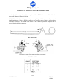
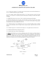
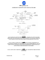
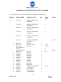
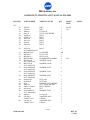
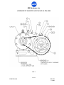
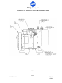
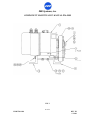
ZEE Systems, Inc.
COMPONENT MAINTENANCE MANUAL Z26-8900
Component
Maintenance
Manual
with
Illustrated Parts List
for
Z26-8900-Series
Motor-Compressor Assembly
1 of 21
CMM Z26-8900
REV. IR
1-28-06
ZEE Systems, Inc.
COMPONENT MAINTENANCE MANUAL Z26-8900
Record of Revisions
REVISION
NO:
ISSUE
DATE
POSTED
DATE
INSERTED BY:
2 of 21
CMM Z26-8900
REV. IR
1-28-06
ZEE Systems, Inc.
COMPONENT MAINTENANCE MANUAL Z26-8900
List of Effective Pages
and
Table of Contents
PAGE
1
2
3
4
5
6
7
8
9
10
11
12
13
14
15
16
17
18
19
20
21
TITLE
COVER PAGE
RECORD OF REVISIONS
LIST OF EFFECTIVE PAGES
1.0 INTRODUCTION
2.0 SPECIAL TOOLS AND EQUIPMENT
. continued
3.0 REPAIR AND REPLACEMENT OF COMPONENTS
ILLUSTRATION 1.
3.1 DRIVE BELT
3.2 COMPRESSOR
ILLUSTRATION 2.
ILLUSTRATION 3.
TABLE 1.
3.3 MOTOR, COMPRESSOR DRIVE
3.4 WIRING
WIRING DIAGRAM 1.
WIRING DIAGRAM 2.
WIRING DIAGRAM 3.
4.0 SERVICING – REFRIGERANT CHARGE
5.0 SERVICE SCHEDULES
6.0 TOLERANCES
7.0 TROUBLE SHOOTING
. continued
8.0 ILLISTRATED PARTS LIST
8.1 EXPLINATION OF SYMBOLS
8.2 IPL Z26-8900 MOTOR COMPRESSOR ASSY
.continued
FIGURE 1
FIGURE 2
FIGURE 3
9.0 SUMMARY OF MODIFICATIONS
9.1 MOD. A
EFFECTIVE DATE / REV
*
*
*
*
*
*
*
*
*
*
*
*
*
*
*
*
*
*
*
*
*
* INTITIAL RELEASE 1-28-06
3 of 21
CMM Z26-8900
REV. IR
1-28-06
ZEE Systems, Inc.
COMPONENT MAINTENANCE MANUAL Z26-8900
1.0 INTRODUCTION
1.1 This Component Maintenance Manual provides information on the maintenance, maintenance schedules
and repair and replacement of parts.
1.2 Refer to the Illustrated Parts List (IPL) in Section 5 when using this manual or ordering replacement parts.
Parts are identified in parenthesis (FIG-ITEM NO.).
1.3 This Motor Compressor (MC) Assembly is part of a vapor cycle air conditioning system. The refrigerant
is R-134a (HFC-134a).
1.3.1 In some installations the compressor is equipped with back seating shut off valves. If the compressor
has back seating valves always check the position of the stem prior to operating the unit. The unit should be
run with the valve in the back seat position (stem full counter-clock wise, out) ONLY. Refer to the
Illustration 1.for back seat valve operation.
NOTE
UNITS ARE SHIPPED WITH THE BACK SEAT VALVE IN THE FRONT SEAT POSITION TO
PREVENT OIL LEAKAGE DURING TRANSIT. ALWAYS PLACE THE VALVE IN THE BACK SEAT
POSITION AND REPLACE THE SEAL CAP PRIOR TO OPERATION. IMPROPER VALVE
POSITION COULD CAUSE DAMAGE TO THE COMPRESSOR. SEE ILLUSTRATION 1.
2.0 SPECIAL TOOLS AND EQUIPMENT
2.1 TOOLS: The following special tools are required to perform the maintenance described in this manual.
ITEM
SOURCE
Dip, Stick, Compressor Oil
Refer to Illustration 2.
Belt deflection gauge.
Commercially available.
14 mm socket
Commercially Available.
17 mm wrenches/sockets
Commercially Available.
Feeler Gauges.
Commercially Available.
External Snap Ring Pliers.
Commercially Available.
External Snap Ring Pliers.
Commercially Available.
Spanner wrench.
Commercially Available.
Graduated Cylinder.
Commercially Available.
4 of 21
CMM Z26-8900
REV. IR
1-28-06
ZEE Systems, Inc.
COMPONENT MAINTENANCE MANUAL Z26-8900
Leak Detector, for HFC-134a
Commercially Available.
Power Supply capable of 28VDC, 50 Amps
Commercially Available.
Refrigerant Recovery/Recycle equipment Commercially Available.
meeting SAE J1990 or J2209 specifications.
Manifold Gauge Set, R-134a, with
automotive service connections.
Commercially Available.
Refrigeration Vacuum Pump.
Commercially Available.
Scale with 0.1 lb. increments (minimum).
Commercially Available.
2.1.2 Refer to applicable ZEE SYSTEMS Service Letter(s) for any additional special tools which may be
required to service the air conditioning system.
2.2 MATERIALS: The following material may be required to perform maintenance described in this manual.
ITEM
SOURCE
MS20995C25 Lock Wire
Commercially Available.
Refrigerant, HFC-134a
Commercially Available.
NOTE
When servicing the air conditioning system always use virgin refrigerant.
DO NOT use recovered refrigerant.
PAG Lubricant, Refrigeration (HFC-134a)
Sanden SP-20 (PAG) or equivalent
MOPAR 82300349 (PAG)
PAG-100
Commercially Available.
Commercially Available
Commercially Available
Commercially Available
NOTE
PAG oil absorbs atmospheric moisture very quickly. Never leave the compressor or
oil container exposed to air for prolonged time. Tightly reseal the oil container
and compressor immediately after exposing the oil to air.
Liquid Detergent, water soluble
Commercially available.
Cloth, lint free
Commercially available.
Tape, Insulation,
Commercially available.
5 of 21
CMM Z26-8900
REV. IR
1-28-06
ZEE Systems, Inc.
COMPONENT MAINTENANCE MANUAL Z26-8900
3.0 REPAIR AND REPLACEMENT OF COMPONENTS. It may be necessary to remove the Z26-8900
Motor Compressor (MC) Assembly from the aircraft to perform the inspections or maintenance described in
this manual. Refer to appropriate aircraft maintenance manual for removal and installation instructions.
CAUTION
AIR CONDITIONING SYSTEM UNDER PRESSURE. APPROPRIATE SAFETY MEASURES
SHOULD BE TAKEN WHEN SERVICING THIS EQUIPMENT. ONLY TRAINED PERSONNEL
WITH APPROVED SAFETY EQUIPMENT SHOULD PERFORM SERVICING DUTIES.
NOTE
IT IS UNLAWFUL TO RELEASE ANY REFRIGERANTS TO THE ATMOSPHERE. USE
APPROVED RECOVERY/RECYCLE EQUIPMENT TO CAPTURE REFRIGERANTS. USE ONLY
LAWFUL MEANS TO DISPOSE OF RECOVERED REFRIGERANTS. CHECK WITH LOCAL
AGENCIES FOR APPROVED DISPOSAL PROCEDURES.
NOTE
CAP ALL OPEN LINES TO PREVENT CONTAMINANTS AND MOISTURE FROM ENTERING
THE SYSTEM.
NOTE
DUE TO THE TIGHT FIT OF THE MOTOR COMPRESSOR CONDENSER ASSY IT MAY BE
NECESSARY TO REMOVE THE MOTOR COMPRESSOR CONDENSER ASSY AND THE
EVAPORATOR TO PERFORM SOME OF THE MAINTENANCE DESCRIBED BELOW.
ILLUSTRATION 1.
3.1 DRIVE BELT (3-20/-21) It may be necessary to remove the Z26-8900 Motor Compressor (MC)
Assembly from the aircraft to change or adjust the belt.
3.1.1 REMOVAL. Extreme care should be taken during maintenance not to strike or use pullers directly
against the hardened (black or grey) area of these pulleys as this may crack or chip the anodized surface. To
remove the belt break the lock wire on the turnbuckle (1-15/-34) and back off the jam nuts (1-40/-41). The
groove on the turnbuckle indicates the end with the left hand thread. Loosen the hardware (1-19/-32/-38) on
the clevis (1-7) the attaches to the bracket on the motor and the rod end hardware (1-6/-26/-32/-38) that
6 of 21
CMM Z26-8900
REV. IR
1-28-06
ZEE Systems, Inc.
COMPONENT MAINTENANCE MANUAL Z26-8900
attaches to the compressor. Loosen the 17 mm nut (2-43) on the 10 mm bolt (2-44) that secures the
compressor to the angles (3-11/-12). You will need two 17 mm wrenching tools. Loosen the belt tension by
turning the turnbuckle to bring the pulleys closer together. When the belt is loose slide it off of the large
compressor pulley (2-18) then the small motor pulley (1-4/-4).
3.1.2 INSPECTION: Inspect the belt for deterioration, damage and fraying. Replace defective belt.
3.1.4 INSTALLATION: Always place the belt over the smaller diameter pulley first then carefully slide the
belt over the larger diameter pulley. Care should be taken to not tear the edges of the belts.
3.1.5 BELT ADJUSTMENT: With the belt in place turn the turnbuckle (1-15/-34) until a tension with a 1/8"
deflection of the belt midway between pulleys with 2-3 pound pull is achieved. Tighten the 17 mm nut (2-43)
that secures the compressor bolt (2-44) to torque of 30 foot-pounds. Secure the jam nuts (1-40/-41) and secure
with lock wire. Tighten the hardware the attaches the clevis (1-29/-32/38) to the motor and rod end (1-26/32/38) to the compressor bracket.
3.1.6 Check the belt alignment before running the motor. Turn the compressor pulley by hand to see that the
belt is properly aligned. Slight striking of the belt against the rim on the small pulleys is normal but not to the
point where chafing occurs. Readjust belt if necessary. Next run the motor and check for smooth operation. If
a belt hops or flutters it is too loose. If the belt is too tight against the pulley rim a discharge of fine dust like
rubber particles will occur. Check the condition of the smaller pulley rim and readjust belts as necessary.
Secure the turnbuckle jam nuts with .025 lock wire. Once the belts are adjusted and all of the hardware is
properly tightened no further adjustments should be necessary if the components are not disturbed.
3.2 COMPRESSOR (2-19) It is necessary to remove the compressor pulley (2-18) to remove the compressor
from the mounting angles. Take care not to damage or loose the shims and key on the compressor shaft.
3.2.1 REMOVAL: If the system has back seat valves move the valve stem to the front seat position to isolate
the refrigerant from the compressor then remove the back seat valves from the compressor.
3.2.1.1 Disconnect the electrical connections to the terminal block or motor for the clutch.
3.2.1.2 Remove the belt as described in 3.1. Remove the bolt that secures the rod end on the turnbuckle.
3.2.1.3 Hold the compressor pulley stationary while removing the 14 mm (1-23) retaining nut. Remove the
internal snap ring (not shown) just under the nut. Now you can slide the clutch plate (1-16) out. Now slide the
pulley (3-18) off the compressor. Take care not to damage or loose the key or shims (not shown).
3.2.1.4 Loosen and remove the 17 mm (2-42) nut that secures the 10 mm bolt (2-44). Remove the 10 mm bolt
and spacers (2-9/-10). The compressor can now be removed from the angles.
3.2.2 INSPECTION: Check for signs oil leakage around the fittings.
3.2.2.1 Check oil level of new system installation. Fashion an oil dipstick from any soft metal bar as shown in
Illustration 1. Determine the angle of the compressor from horizontal as shown in Illustration 2. Remove the
oil fill plug on top of the compressor, take care not damage the seal. Place the dipstick in the opening; make
7 of 21
CMM Z26-8900
REV. IR
1-28-06
ZEE Systems, Inc.
COMPONENT MAINTENANCE MANUAL Z26-8900
sure the dip stick goes in past the crankshaft and pistons. Refer to TABLE 1. for correct oil level and add oil
as necessary. Return and tighten oil fill plug.
3.2.2.2 Check oil level of existing system. If you are replacing a failed compressor from an existing
installation drain the oil from the defective compressor and record the amount. Drain the oil from the new
replacement compressor. Add back the same amount of oil to the new replacement compressor that was
removed from the defective compressor.
Dip Stick
ILLUSTRATION 2.
Determine the angle of the compressor relative to horizontal.
ILLUSTRATION 3.
8 of 21
CMM Z26-8900
REV. IR
1-28-06
ZEE Systems, Inc.
COMPONENT MAINTENANCE MANUAL Z26-8900
3.2.5 INSTALLATION: With the compressor pulley removed, align the compressor and spacers (2-9/-10)
with angles (3-11/-12) and slide the 10 mm x 150 mm bolt (2-44) into position. Do not forget the flat washer
(2-42) under bolt head before inserting. Make sure the bolt head is on the pulley side. Tighten the 17 mm nut
just enough to secure the compressor but loose enough to adjust the belt.
3.2.5.1 Slide the compressor pulley (2-18) assembly on the compressor.
3.2.5.2 Align the key way and place the clutch plate (1-16) on the compressor shaft. Install the internal snap
ring. Replace the 14 mm (1-23) retaining nut and torque to 11-15 lb-ft (15-21 N-m)
3.2.5.3 Check the air gap between the clutch plate and the pulley with the feeler gauge that a clearance of
.016” - .031” (0.4 – 0.8mm). If the gap is not even around the clutch, gently tap down at the high spots. If the
overall air gap is out of specification remove the clutch plate and add or subtract shims as necessary.
3.2.5.4 Remove the bracket (1-14) from the defective compressor and attach the bracket to the replacement
compressor and tighten.
3.2.5.5 Attach the rod end (1-6) of the turnbuckle to the bracket (1-14) on the compressor. Do not fully
tighten at this time.
3.2.5.6 Attach and adjust the belt as described in Section 3.1 through 3.1.6.
3.2.5.7 Check the operation of the clutch plate (1-16) and coil (1-17). If the wires are connected to a terminal
block or strip DO NOT apply power directly across pins C and D on the terminal block. Remove the (+) wire
from the compressor coil at pin C on terminal block. Apply 28 VDC across the compressor coil (+) wire and
pin D ( - ) on the terminal block. The clutch should pull in to the pulley. Remove power and the clutch should
release (move away) and the pulley will be free. Connect the coil (+) wire back to pin C on the terminal
block. Refer to Wiring Diagram 1 for schematic.
3.3 MOTOR, COMPRESSOR DRIVE (3-3) Prior to disassembly mark the support positions (3-5/-8) for
proper alignment during reassembly. The mounting holes are not centered on the supports (3-8/-5) and the
motor is not centered between the angles.
NOTE
USE ONLY THE SPECIFIED MOUNTING HARDWARE. INCORRECT BOLT
LENGTH CAN CAUSE A SHORT IN THE MOTOR WINDINGS.
3.3.1 REMOVAL: Disconnect the positive and negative leads to the motor. Remove the clamp and all
remaining attached wiring from the motor.
3.3.1.1 Remove and set aside the belt in accordance with paragraph 3.1.
3.3.1.2 Break the lock wire and remove the four bolts and hardware (1-30/-36/-39) that attach the supports to
the angles (3-11/-12).
9 of 21
CMM Z26-8900
REV. IR
1-28-06
ZEE Systems, Inc.
COMPONENT MAINTENANCE MANUAL Z26-8900
3.3.1.3 To remove the supports (3-5/-8) from the motor, loosen and remove the four bolts and hardware (325/-35/-37). Mark their position for proper reassembly.
3.3.1.4 Use a spanner wrench to hold the motor pulley (1-2/-4). Loosen and remove the bolt (3-28) and
hardware (3-36/-39) spacer (3-1) and pulley. Inspect the motor pulley for damaged or rounded teeth. Replace
if damaged.
3.3.2 INSPECTION: Refer to Service Letter 58-001 or 99-800 for brush inspection information.
3.3.3 INSTALLATION: Place the motor pulley on the shaft. Make sure the flats of the pulley mate with the
flats on the motor shaft. Place the spacer and hardware (3-1/-36/-39) on the end of the pulley. Using a spanner
wrench hold the motor pulley and tighten the bolt (3-28).
3.3.3.1 Attach the supports (3-5/-8) and hardware (3-25/-35/-37) to the motor. Make sure they are aligned
properly or the motor pulley will not be aligned with the compressor pulley. Tighten bolts and secure with
lock wire.
3.3.3.2 Attach the supports (3-5/-8) and motor to the angles (3-11/-12), tighten and secure with lock wire.
3.3.3.3 Install and adjust the belt as described in section 3.1.
3.3.3.4 Attach wiring to motor. Refer to Wiring Diagram 1.
3.4 WIRING The Z26-8900 is part of the air conditioning system. The circuitry may include features to
control the Condenser Power Fan, clutch, High/Low Pressure Switch to disengage the clutch should an
unsafe pressure condition exist and a motor over-temp switch that will shut down the motor if the case
temperature exceeds 450ºF. The circuits may be connected through a Terminal Block which allows for easy
replacement of components. Refer to the following diagrams for example circuit schematics.
10 of 21
CMM Z26-8900
REV. IR
1-28-06
ZEE Systems, Inc.
COMPONENT MAINTENANCE MANUAL Z26-8900
CAUTION
AIR CONDITIONING SYSTEM UNDER PRESSURE. APPROPRIATE SAFETY MEASURES
SHOULD BE TAKEN WHEN SERVICING THIS EQUIPMENT. ONLY TRAINED PERSONNEL
WITH APPROVED SAFETY EQUIPMENT SHOULD PERFORM SERVICING DUTIES.
NOTE
IT IS UNLAWFUL TO RELEASE ANY REFRIGERANTS TO THE ATMOSPHERE. USE
APPROVED RECOVERY/RECYCLE EQUIPMENT TO CAPTURE REFRIGERANTS. USE ONLY
LAWFUL MEANS TO DISPOSE OF RECOVERED REFRIGERANTS. CHECK WITH LOCAL
AGENCIES FOR APPROVED DISPOSAL PROCEDURES.
NOTE
CAP ALL OPEN LINES TO PREVENT CONTAMINANTS AND MOISTURE FROM ENTERING
THE SYSTEM.
11 of 21
CMM Z26-8900
REV. IR
1-28-06
ZEE Systems, Inc.
COMPONENT MAINTENANCE MANUAL Z26-8900
4.0 SERVICING - REFRIGERANT CHARGE
4.1 Refer to Aircraft maintenance manual or ZEE Systems, Inc. Service Letter Z26-1 for recommended
refrigerant charging service instructions.
5.0 SERVICE SCHEDULES
5.1 MAINTENANCE SCHEDULE The maintenance and service schedules are ZEE Systems, Inc.
recommended intervals. Actual operating and environmental conditions may require more frequent service.
ITEM
DESCRIPTION
INSPECTION
INTERVAL *
R&R/T.B.O.
HRS
Z26-8900
M-C
EVERY 250 HRS* - INSPECT FOR LOOSE,
DAMAGED ITEMS.CHECK FOR
SIGNS OF OIL LEAKS.
2,000
DRIVE BELT**
EVERY 250 HRS* - INSPECT AS PER
SECTION 3.1.2
MOTOR, DRIVE, **
COMPRESSOR
COMPRESSOR**
EVERY 1000 HRS* - INSPECT AS PER
SECTION 3.3.2 AND SERVICE
LETTER 58-001 or 99-800.
1,000
2,000
(NEW) AFTER THE FIRST 100 HOURS - INSPECT
AS PER SECTION 3.2.2.1
EVERY 500 HRS - INSPECT AS PER
SECTION 3.2.2
2,000
* UNIT OPERATING TIME
** COMPONENT IS PART OF THE Z26-8900 MOTOR-COMPRESSOR ASSEMBLY.
REFER TO SANDEN “SANDEN SD COMPRESSOR SERVICE MANUAL” FOR ADDITIONAL
COMPRESSOR SERVICE INFORMATION.
6.0 TOLERANCES
6.1 COMPRESSOR OIL. NEW refer to Illustration 2 and Illustration 3 and Table 1. REPLACEMENT refer
to Section 3.2.2.2.
12 of 21
CMM Z26-8900
REV. IR
1-28-06
ZEE Systems, Inc.
COMPONENT MAINTENANCE MANUAL Z26-8900
6.2 CLUTCH. When assembled an air gap of .016” - .031” (0.4 – 0.8mm) between the pulley and clutch
plate.
6.2 REFRIGERANT CHARGE. Refer to aircraft maintenance manual or ZEE Systems, Inc. Service Letter
Z26-1.
6.3 BRUSH LENGTH, COMPRESSOR DRIVE MOTOR. The minimum brush length on the drive motor is
0.750" (19mm). Refer to SIL 58-001.
6.4 TORQUE VALUES. If not specified, use standard torque values for bolts.
14 mm Pulley Nut 11-15 lb-ft (15-21 N-m)
17 mm (10 mm Compressor Bolt) Nut 30 lb-ft (42 N-m)
7.0 TROUBLE SHOOTING
TROUBLE
POSSIBLE CAUSE
REMEDY
Compressor Motor
trips circuit breaker or
current limiter
Motor shorted.
Motor brushes worn
beyond limits.
Replace Motor.
Short in wiring.
Check wiring to motor,
repair as required.
Motor open.
Motor brushes worn
beyond limits.
Replace Motor.
Short in wiring.
Check wiring to motor,
repair as required.
Improper belt
tension.
Adjust belt to correct
tension.
Worn, damaged or
loose or over
tightened mounts.
Adjust or replace
mounts.
Open in system.
Check compressor head
gasket. Check Hoses or
tubing for holes.
Check connections.
Compressor Motor
inoperative.
Excessive vibration at
Motor/Compressor.
Quick refrigerant loss.
13 of 21
CMM Z26-8900
REV. IR
1-28-06
ZEE Systems, Inc.
COMPONENT MAINTENANCE MANUAL Z26-8900
TROUBLE
POSSIBLE CAUSE
REMEDY
Replace defective component. Service system
Defective O-Ring.
Replace defective
O-Ring. Service system
Loose connections.
Tighten connections.
Service system
Slow refrigerant loss.
Loose connections.
Tighten connections.
Service system
Low or no cooling. Low
Pressures.
Incorrect Back Seat Valve
position.
Place Back Seat Valve
In proper position for
normal operation.
Low refrigerant.
Service as necessary.
Low or high discharge
pressures.
Check refrigerant charge.
Service as necessary.
Defective Pressure Switch
Replace Pressure Switch.
Defective Coil.
Replace Coil.
Defective wiring.
Refer to Diagram 1. Repair as
necessary.
Power Condenser Fan
defective.
Replace Power Condenser
Fan Assembly.
Compressor clutch does not
engage.
MC and Clutch start up normally.
Clutch disengages after a short time.
14 of 21
CMM Z26-8900
REV. IR
1-28-06
ZEE Systems, Inc.
COMPONENT MAINTENANCE MANUAL Z26-8900
8.0 ILLUSTRATED PARTS LIST
8.1 EXPLANATION OF SYMBOLS:
ALT - The Part Number shown is an approved alternate, either part number may be used.
MOD "X" Refers to modification information of this part as applicable to this assembly.
NP - Not Procurable individually, see next higher assembly.
NS - Not Shown
OBS - Obsolete
USAGE/QTY - This identifies parts used on specific applications (not common to all units). If no code is
stated the part is common to all dash numbers.
.. - Part of higher assembly.
*/# - See explanation at end of parts list.
“AN”, “MS” and “NAS” equivalent hardware is considered to be approved alternates for each other and may be
used. The most common are as follows:
PART NUMBER
ALTERNATE
DESCRIPTION
AN345-516
MS35650-3312
NUT, MACHINE
AN364-624A
MS21083N6
LOCK NUT
AN365-428A
MS21044N4
LOCK NUT
AN365-832A
MS21044N08
LOCK NUT
AN501A10-6
MS35266-61
SCREW
AN935-416
MS35338-44
WASHER, LOCK
AN935-516
MS35338-45
WASHER, LOCK
AN935-616
MS35338-46
WASHER, LOCK
AN935-8
MS35338-42
WASHER, LOCK
AN960-416
NAS1149F0463P
WASHER, FLAT
AN960-416L
NAS1149F0432P
WASHER, FLAT
AN960-516
NAS1149F0563P
WASHER, FLAT
AN960-516L
NAS1149F0532P
WASHER, FLAT
AN960-616
NAS1149F0663P
WASHER, FLAT
AN960-616L
NAS1149F0632P
WASHER, FLAT
AN960-8L
NAS1149FN816P
WASHER, FLAT
15 of 21
CMM Z26-8900
REV. IR
1-28-06
ZEE Systems, Inc.
COMPONENT MAINTENANCE MANUAL Z26-8900
8.2 ILLUSTRATED PARTS LIST Z26-8900 MOTOR COMPRESSOR ASSEMBLY.
FIG-ITEM
PART NUMBER
NOMENCLATURE
1/2/3
Z26-8900-1
MOTOR COMPRESSOR
ASSEMBLY
Z26-8900-2
MOTOR COMPRESSOR
ASSEMBLY
B
Z26-8900-3
MOTOR COMPRESSOR
ASSEMBLY
C
Z26-8900-4
MOTOR COMPRESSOR
ASSEMBLY
D
Z26-8900-5
MOTOR COMPRESSOR
ASSEMBLY
E
Z26-8900-5
MOTOR COMPRESSOR
ASSEMBLY
F
SZ41-019-5
SZ43-008-3
SZ58-003-1
ALT: SZ58-003-2
Z99-800-1
Z99-800-1 (MOD E)
SZ83-041-4
Z14-401-1
Z25-404-1
Z25-404-2
Z26-400-1
Z26-401-1
Z26-401-2
Z26-402-1
Z26-402-2
Z26-403-1
Z26-404-1
Z26-405-1
Z99-421-7
Z99-421-9
Z99-423-1
Z99-915-4
SPACER
PULLEY, MOTOR
MOTOR
1
1
1
PULLEY
SUPPORT
CLEVIS
ROD END
SUPPORT
SPACER
SPACER
ANGLE
ANGLE
BRACKET
BRACKET
TURNBUCKLE BARREL
CLUTCH PLATE
COIL ASSY
PULLEY ASSY
COMPRESSOR
1
1
1
2
1
1
2
1
1
1
1
1
1
1
1
1
1
1
-1
-2
-3
-4
-5
-6
-7
-8
-9
-10
-11
-12
-13
-14
-15
-16
-17
-18
-19
QTY
USAGE
CODE
A
NOTES
MOD A
A,B,E,F
A,B,C,D
E
F
C,D
MOD A
A,B,E,F
16 of 21
CMM Z26-8900
REV. IR
1-28-06
ZEE Systems, Inc.
COMPONENT MAINTENANCE MANUAL Z26-8900
FIG-ITEM
PART NUMBER
NOMENCLATURE
QTY
USAGE
CODE
-20
-21
-22
-23
-24
-25
-26
-27
-28
-29
255L075
270L100
400649-1
8M-1.25
AN4H5A
AN4H17A
AN5-11A
AN5-12A
AN6-6A
AN6-12A
BELT
BELT
I.D. PLATE
NUT, LOCK, METRIC
BOLT
BOLT
BOLT
BOLT
BOLT
BOLT
1
1
1
1
2
4
1
1
1
2
A,B,E,F
C,D
-30
AN76A11
ALT: MS20074-06-11
MS20995C025
MS21045-5
MS21045-6
MS21251B6S
MS35338-44
ALT: AN935-416
MS35338-46
ALT: AN935-616
NAS1149F0463P
ALT: AN960-416
NAS1149F0563P
ALT: AN960-516
NAS1149F0663P
ALT: AN960-616
NAS509-5R
NAS509-5L
M10
10M-1.50
10M-1.5x150mm
AN316-6R
NAS1149F0632
ALT: AN960-616L
400649-1
Z26-200-8
..MS28775-013
Z26-200-10
..MS28775-015
BOLT
4
LOCK WIRE
NUT, LOCK
NUT, LOCK
TURNBUCKLE BARREL
WASHER, LOCK
AR
2
2
1
6
WASHER, LOCK
5
WASHER, FLAT
6
WASHER, FLAT
4
WASHER, FLAT
9
NUT, JAM
NUT, JAM
WASHER, FLAT, METRIC
NUT, LOCK, METRIC
BOLT, METRIC
NUT
WASHER, FLAT
1
1
2
1
1
2
4
I.D. PLATE
ADAPTER, B.S.V.
O-RING
ADAPTER, B.S.V.
O-RING
1
1
1
1
1
NOTES
1/2/3
-31
-32
-33
-34
-35
-36
-37
-38
-39
-40
-41
-42
-43
-44
-45
-46
-47
NS
NS
C,D
17 of 21
CMM Z26-8900
REV. IR
1-28-06
ZEE Systems, Inc.
COMPONENT MAINTENANCE MANUAL Z26-8900
FIG. 1
18 of 21
CMM Z26-8900
REV. IR
1-28-06
ZEE Systems, Inc.
COMPONENT MAINTENANCE MANUAL Z26-8900
FIG. 2
19 of 21
CMM Z26-8900
REV. IR
1-28-06
ZEE Systems, Inc.
COMPONENT MAINTENANCE MANUAL Z26-8900
FIG. 3
20 of 21
CMM Z26-8900
REV. IR
1-28-06
ZEE Systems, Inc.
COMPONENT MAINTENANCE MANUAL Z26-8900
9.0 SUMMARY OF MODIFICATIONS
9.1 MOD “A”. This modification applies to the Z26-8900-5 MC only. The modification is noted when the
Z99-800-1 Motor used has MOD E. Mark an “X” in the “A” block of the Modification Status section of
the I.D. Plate.
21 of 21
CMM Z26-8900
REV. IR
1-28-06