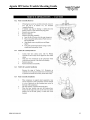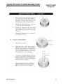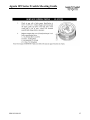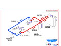
1
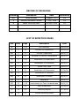
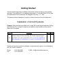
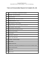
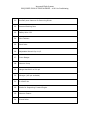
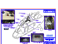
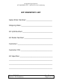
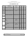
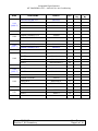
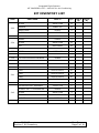
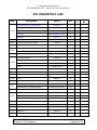
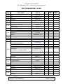
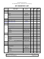
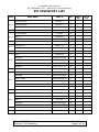
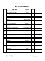
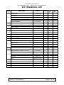
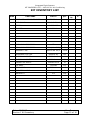
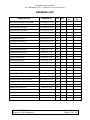
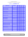
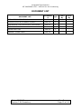
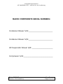
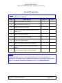
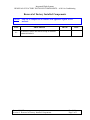
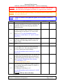
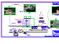
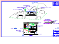
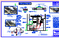
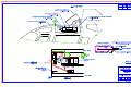
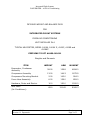
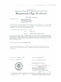
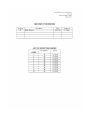
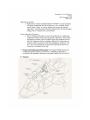
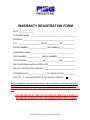
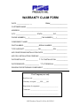
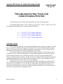
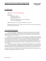
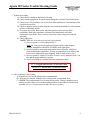
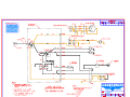
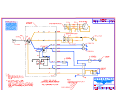
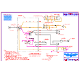
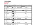
Air Conditioning
System
Installation Manual
For
A109-00-011
(IM-A109-00-011 Rev B, 24 September 2009)
RECORD OF REVISIONS
Revision
Description
Date
Revised By
N/C
Initial Release
1 August, 2007
IFS
A
Revised Hardware Callouts
7 July, 2009
IFS
B
Added A109A/Warranty
24 Sept. 2009
IFS
LIST OF EFFECTIVE PAGES
Rev
Sect.
Page
Description
Date
B
1
1-14
Kit Inventory
09/24/09
A
2
1-4
Aircraft Pre-inspectioin
09/24/09
N/C
3
1-2
Aircraft Preperation
08/01/07
N/C
4
1-2
Removal of Factory Components
08/01/07
A
5
1-10
Installation of Evaporators
09/24/09
N/C
6
1-2
Installation of Condenser
08/01/07
N/C
7
1-1
Section Not Used
08/01/07
A
8
1-3
Installation of Compressor
07/06/09
N/C
9
1-3
Installation of Electrical
08/01/07
N/C
10
1-2
Installation of Hoses
08/01/07
N/C
11
1-2
Paperwork
08/01/07
N/C
12
1-15
Instructions for Cont. Airworthiness
08/01/07
A
13
1-4
Parts Breakdown
09/24/09
C
14
1-6
Warranty/Repair
11/04/09
N/C
15
1-5
Trouble Shooting Guide.
08/01/07
Getting Started
The air conditioning system installation instructions are laid out step-by-step starting
with one (1) through ten (9), for installation and eleven (11) through fifteen (15) for care
and airworthiness, the instructions are designed to be easy – to – use.
The example below is designed to give you a basic overview of how the steps work.
Installation of Aircraft Systems
Example: When the parts are called out in a step: 5.2, locate the part and parts that go
with this step (5.2). It is best to organize your parts by step numbers so they can be
drawn from as needed.
Step
5.2
Procedure
Mech Insp
Position Cockpit Air Duct Assembly P/N 520062 using drawings 8A109 Sheet 1 of 1 and 5-A109 Sheet 3 of 4. For A109 E Installation
utilize drawings 8-1-A109P Sheet 1 of 1 and 5-1-A109P Sheet 3 of 4.
Should you have any questions, problems or need technical support, do not hesitate to
call, fax, E-mail, or write us:
Phone:
Fax:
1-817-624-6600
1-817-624-6601
E-Mail: [email protected]
Integrated Flight Systems
REQUIRED TOOLS/CONSUMABLES – A109 Air-Conditioning
Tools and Consumables Required to Complete the Job
1.
Drill ¼ or 3/8 Capacity / Straight and 90 degrees
2.
Rivet Gun - #4 & #5 Rivet Set
3.
Blind Rivet Puller
4.
Assorted Drill Bits - 40, 30, 10, ¼, & 21
5.
Standard Wrenches - ¼-1¼
6.
Metric Wrenches - 5mm to 19mm
7.
Standard Sockets - ¼ to ¾ cap Ratchet & Extensions
8.
Metric Sockets - 5mm to 19mm
9.
Torque Wrench (For Pulley) 200 in-lbs
10.
Rotary File (Die Grinder)
11.
Drum Sander
12.
Hole Finder - #30 & #10
13.
Cleco - #30, #21 & #40
14.
C-Clamps – Vise Grip Clamps
15.
Wire Cutters
16.
Phillips Screw Driver
17.
Torque-Bite (For Belly Pan) Pan American Tool 170-10 & 170-8 Power Torque
18.
Common Screw Drivers
19.
Cape Chisel
20.
Center Punch
Integrated Flight Systems
REQUIRED TOOLS/CONSUMABLES – A109 Air-Conditioning
21.
6oz Ball-peen Hammer for Removing Rivets
22.
Assorted Bucking Bars
23.
Safety Wire .032
24.
Wire Twisters
25.
Steel Ruler
26.
Adjustable Wrench Cap 1-1/2
27.
Freon Gauges
28.
Vacuum Pump
29.
Gauge Manifold 0 to 500 psi
30.
Nitrogen (400 psi available)
31.
R-134A 3 lbs
32.
Blocks for Supporting Forward Engine
33.
Vacuum Cleaner
34.
Rivnut Puller
Integrated Flight Systems
KIT INVENTORY LIST – A109-00-011 Air Conditioning
Step 1
Kit Inventory
Date: 09/24/09
Section 1 Kit Inventory
Rev. B
Page 1 of 16
Integrated Flight Systems
KIT INVENTORY LIST – A109-00-011 Air Conditioning
KIT INVENTORY LIST
Sales Order Number:_________________________
Shipping Date:______________________________
Kit S/N Number:_____________________________
Kit Model Number:___________________________
Customer:__________________________________
Customer PO:_______________________________
Kit Specifies:________________________________
__________________________________________
__________________________________________
__________________________________________
Date: 09/24/09
Section 1 Kit Inventory
Rev. B
Page 2 of 16
Integrated Flight Systems
KIT INVENTORY LIST – A109-00-011 Air Conditioning
KIT INVENTORY LIST
STEP
PART NAME
PART #
QTY
520062
1
5.2
COCKPIT AIR DUCT ASSEMBLY
5.7
EVAPORATOR ASSEMBLY
560043-0
1
5.8
CONDENSER LEG SUPPORT ASSY.
510227-1
1
5.9
CONDENSER ASSEMBLY
550022-0
1
SL601-3-3A
6
(504SE1032-06-02)
(6)
100181
2
090018-1
4’ ft
AN3-5A
6
AN960-10
6
MS21059-L3
14
CCR264-SS3-3
28
A10K80
14
AN525-10R8
12
AIR DEFLECTOR R.H.
260916
1
AIR DEFLECTOR L.H
260917
1
CR3243-4-4
8
5.13
5.15
5.16
SHURLOCK
(ALTERNATE: DELRON INSERT)
“Y” DRAIN
DRAIN HOSE
BOLT
WASHER
NUTPLATE
5.21
RIVET
(ALT: RIVNUT)
SCREW
5.23
RIVET
Date: 09/24/09
Section 1 Kit Inventory
Chk’d
By
Verf’d
By
Rev. B
Page 3 of 16
Integrated Flight Systems
KIT INVENTORY LIST – A109-00-011 Air Conditioning
STEP
5.23
(A109 E)
5.26
5.26
(A109 E)
5.28
5.28
(A109 E)
PART NAME
PART #
QTY
AIR DEFLECTOR R.H.
260916-P
1
AIR DEFLECTOR L.H.
260917-P
1
CR3243-4-4
4
WEMAC DOUBLER L.H.
260889
1
WEMAC DOUBLER R.H.
260890
1
WEMAC DOUBLER L.H.
260889-P
1
WEMAC DOUBLER R.H.
260890-P
1
RIVET
MS20470AD4-3
40
RIVET
MS20470AD4-4
40
RIVET
MS20426AD4-3
30
RIVET
MS20426AD4-4
30
RIVET
MS20470AD4-3
40
RIVET
MS20470AD4-4
40
250276
2
MS21059-L3
8
CCR264-SS3-3
16
AIR DUCT
250275
4
RIVET
ABA4-4
16
RIVET
WEMAC SUPPORT
5.29
NUTPLATE
RIVET
5.30
Date: 09/24/09
Section 1 Kit Inventory
Chk’d
By
Verf’d
By
Rev. B
Page 4 of 16
Integrated Flight Systems
KIT INVENTORY LIST – A109-00-011 Air Conditioning
KIT INVENTORY LIST
STEP
PART NAME
PART #
QTY
AN525-10R8
14
AN960-10L
14
BAND CLAMP
060035
2
DUCT 7”
060007
6” In.
WEMAC
030012
4
SCREW
AN525-10R8
16
NUT
MS21044N3
16
5.35
SCREW
AN525-10R8
8
5.36
CO-PILOTS BULKEAD DOUBLER
260866
1
5.36
CO-PILOTS BULKEAD DOUBLER
260866-P
1
RIVET
MS20470AD4-3
30
RIVET
MS20470AD4-4
30
RIVET
MS20470AD4-5
20
RIVET
MS20470AD4-6
15
520061-109
1
080036
1
AN525-10R8
4
SCREW
5.33
5.34
5.41
WASHER
RETURN AIR DUCT ASSEMBLY
SCREEN 9.8 x 7.4 RETURN AIR
5.42
SCREW
CLIP NUT
WASHER
Date: 09/24/09
Section 1 Kit Inventory
RM52LHA4972-10-02
AN970-3
Chk’d
By
Verf’d
By
4
4
Rev. B
Page 5 of 16
Integrated Flight Systems
KIT INVENTORY LIST – A109-00-011 Air Conditioning
KIT INVENTORY LIST
STEP
PART NAME
RETURN AIR DUCT ASSEMBLY
SCREEN 9.8 x 7.4 RETURN AIR
5.42
SCREW
CLIP NUT
WASHER
5.43
5.45
5.46
PART #
QTY
520061-P
1
080036
1
AN525-10R8
3
RM52LHA4972-10-02
3
RETURN AIR DUCT-LOWER
250286
1
O.B. VERTICAL SUPPORT ASSEMBLY
510231
1
I.B. VERTICAL SUPPORT ASSEMBLY
510230
1
PLATE ASSEMBLY
510232
2
RIVET
ABA4-4
8
260912-1
1
CR3243-4-4
2
RIVET
5.48
RETURN AIR DUCT - UPPER
250285
1
5.51
RIVET
ABA4-4
40
SL601-3-3A
6
(504SE1032-06-02)
(6)
DUCT
060007
12’ in
5.53
BAND CLAMP
060035
2
5.56
3.4 NIPPLE
250279
1
5.57
DOUBLER
261510
2
5.57
RIVET
CR3243-4-2
48
5.52
SHURLOCK
(ALTERNATE: DELRON INSERT)
Date: 09/24/09
Section 1 Kit Inventory
Verf’d
By
3
AN970-3
DUCT MOUNT
Chk’
d
Rev. B
Page 6 of 16
Integrated Flight Systems
KIT INVENTORY LIST – A109-00-011 Air Conditioning
KIT INVENTORY LIST
STEP
PART NAME
PART #
QTY
5.58
BOLT
AN3-13A
3
5.58
NUT
AN365-1032
3
5.58
WASHER
AN970-4
3
5.58
WASHER
AN960-10
3
AIR DUCT 3-1/2” X 24”
060024-1
24” in
BAND CLAMP
060040
2
DZUS SUPPORT ASSEMBLY
510300
2
50-052-1
2
MS20426AD3-4
8
50-052-5-1
2
AFT CABIN DUCT ASSEMBLY
520066-A
1
AFT CABIN DUCT ASSEMBLY
520066
1
DUCT PLACARD
120071
2
SL601-3-3A
(504SE1032-06-02)
6
261009
3
AN525-10R8
3
AN960-10
3
3” HOSE NIPPLE
250509
1
RIVET
ABA4-4
4
AN525-10R8
6
AN960-10
15
AN3-4A
2
AN960-10
2
5.59
5.63
CAMLOC
RIVET
5.64
CAMLOC
(For A109A MODEL ONLY)
5.65
SHURLOCK
(ALTERNATE: DELRON INSERT)
AFT CABIN DUCT BRACKET
SCREW
WASHER
5.66
5.67
5.68
SCREW
WASHER
BOLTS
WASHER
Date: 09/24/09
Section 1 Kit Inventory
Chk’d
By
Rev. B
Page 7 of 16
Verf’d
By
Integrated Flight Systems
KIT INVENTORY LIST – A109-00-011 Air Conditioning
KIT INVENTORY LIST
STEP
6.0
6.1
PART NAME
PART #
QTY
3” DOUBLER
260867
4
BOLTS
AN3-4A
8
NUTS
AN365-1032
6
BOLT
AN3-13A
2
WASHER
AN970-4
4
8.4
COMP. BRKT. ASSY.
510255
1
8.4
(A109E)
COMP. BRKT. ASSY.
510255-P
1
DRIVE PULLEY
300333-2
1
060031
2
060031-1
2
NAS1304-4H
5
WASHER
NAS1149F0463P
5
WASHER
NAS1149F0432P
5
BOLT
AN4H7A
4
BOLT
AN4H10A
4
WASHER
NAS1149F0463P
8
WASHER
NAS1149F0432P
8
MS21044-N4
4
530089
1
010001-3-O
1
AN6-H10A
2
WASHER
NAS1149F0663P
2
WASHER
NAS1149F0632P
2
BELTS ½” X 30.5
8.5
8.6
(A109E) BELTS
BOLTS
NUT
8.7
(ALT: MS20364-424C)
FIREWALL BOX ASSEMBLY
COMPRESSOR
BOLT
8.8
Date: 09/24/09
Section 1 Kit Inventory
Chk’d
By
Verf’d
By
Rev. B
Page 8 of 16
Integrated Flight Systems
KIT INVENTORY LIST – A109-00-011 Air Conditioning
KIT INVENTORY LIST
STEP
8.12
8.13
PART NAME
PART #
QTY
SHIM CALIPER
261012-1
2
SHIM CALIPER
261013-1
2
SHIM CALIPER
261014-1
2
STRUT BRACE
300330
1
AN4H11A
2
NAS1149F0463P
1
FITTING 90°
AN833-4D
1
NUT
AN924-4D
1
BOLT
AN3H11A
2
NAS1149F0363P
4
MS21044-N3
2
SPACER
3/16” I.D. X .5”
2
SPACER
3/16” I.D. X .7”
2
AN3-3A
17
WASHER
NAS1149F0363P
14
ADEL CLAMP
MS21919WDG-10
3
AN365-1032A
3
FIREWALL ANGLE
300337
1
BOLT
AN3-3A
4
NAS1149F0363P
4
MS20615-3M3
12
BOLT
WASHER
8.14
WASHER
8.15
NUT
BOLT
8.16
8.17
NUT
WASHER
RIVET
Date: 09/24/09
Section 1 Kit Inventory
Chk’d
By
Verf’d
By
Rev. B
Page 9 of 16
Integrated Flight Systems
KIT INVENTORY LIST – A109-00-011 Air Conditioning
KIT INVENTORY LIST
STEP
PART NAME
PART #
QTY
BELT ADJUSTMENT ASSEMBLY
530088
1
BELT BRACKET ASSEMBLY
510263
1
MS21044N8
3
NAS1149F0863P
3
AN6H10A
2
WASHER
NAS1149F0663P
2
WASHER
NAS1149F0632P
2
WASHER
NAS1149F0616P
2
ELECT. PANEL ASSEMBLY
540028-C-3
1
SHURLOCK
SL601-3-3A
4
NUT
8.18
9.1
9.3
9.4
9.5
WASHER
BOLT
(ALTERNATE: DELRON INSERT)
BOLT
9.10
4
WASHER
AN960-10
4
HARNESS ASSEMBLY
540045-1
1
HARNESS ASSEMBLY
540059-1
1
AN3-4A
1
MS21059-L3
1
CCR264-SS3-3
4
AN960-10
1
HI PRESSURE SWITCH
090004
1
LOW PRESSURE SWITCH
050107
1
HANDSHAKE
14-16
6
HEATSHRINK
¼” X 6”
4
NUTPLATE
RIVET
WASHER
9.11
(504SE1032-06-02)
AN3-4A
BOLT
Date: 09/24/09
Section 1 Kit Inventory
Chk’d
By
Rev. B
Page 10 of 16
Verf’d
By
Integrated Flight Systems
KIT INVENTORY LIST – A109-00-011 Air Conditioning
KIT INVENTORY LIST
STEP
PART NAME
PART #
QTY
050012-9
1
120205
1
#8
6’
RING TERMINAL
#8 X 8
2
RING TERMINAL
#8 X 3/8
1
FWD SWITCH ASSEMBLY
540060
1
HEAT SHRINK
¼ X 6”
2
AFT SWITCH ASSEMBLY
540061
1
HEAT SHRINK
¼ X 6”
2
HOSE ASSEMBLY
570053-0
1
HOSE ASSEMBLY
570058-1-0
1
MS21919WDG-14
4
MS35207-265
4
AN960-10
4
570059-1-0
1
MS21919WDG-16
4
MS35207-265
4
AN960-10
4
AN365-1032A
4
C/B 50 AMP
PLACARD
9.15
9.17
9.18
10.0
10.1
WIRE
ADEL CLAMP
SCREW
WASHER
HOSE ASSY #10 COMP. TO EVAP.
ADEL CLAMP
10.2
SCREW
WASHER
NUT
Date: 09/24/09
Section 1 Kit Inventory
Chk’d
By
Verf’d
By
Rev. B
Page 11 of 16
Integrated Flight Systems
KIT INVENTORY LIST – A109-00-011 Air Conditioning
KIT INVENTORY LIST
STEP
PART NAME
PART #
QTY
570052-0
1
MS21919WDG-10
1
AN525-10R7
1
AN960-10
1
CORK INSULATION TAPE
PT1
2’
FOAM INSULATION TAPE
K501 (Alt: K502)
60’
PROSEAL™ 890
890-B2 OR -B1/2
1 Pint
ALUMINUM FOIL TAPE
NASHUA 322
100’
CHERRY MAX RIVET
CR3243-4-3
20
CHERRY MAX RIVET
CR3243-4-4
20
CHERRY POP RIVETS
CCR264-SS3-6
10
TIE WRAP
TY5224M
100
TIE BLOCKS
ZZCR4HM
25
SW44
8’
A-4
1 Qt.
10.3
HOSE ASSY. #6 EVAP. TO DRIER
10.3
ADEL CLAMP
10.3
SCREW
10.3
WASHER
3/4" SPIRAL WRAP
METALSET™
Date: 09/24/09
Section 1 Kit Inventory
Chk’d
By
Verf’
d
Rev. B
Page 12 of 16
Integrated Flight Systems
KIT INVENTORY LIST – A109-00-011 Air Conditioning
DRAWING LIST
DRAWING LIST
DRAWING #
REV
QTY
AIR CONDITIONING OVERVIEW
1-1-A109 (1 of 1)
A
1
ELECTRICAL ROUTING
2-1-A109 (1 of 3)
A
1
ELECTRICAL DIAGRAM
2-1-A109 (2 of 3)
A
1
ELECTRICAL DIAGRAM
2-1-A109 (3 of 3)
A
1
PLUMBING DIAGRAM
3-1-A109 (1 of 3)
A
1
PLUMBING DIAGRAM
3-1-A109 (2 of 3)
A
1
PLUMBING ROUTING
3-1-A109 (3 of 3)
A
1
EVAPORATOR INSTALL
4-A109 (1 of 2)
B
1
EVAPORATOR INSTALL
4-A109 (2 of 2)
B
1
AIR DISTRIBUTION
5-A109 (1 of 4)
B
1
AIR DISTRIBUTION
5-A109 (2 of 4)
B
1
AIR DISTRIBUTION
5-A109 (3 of 4)
B
1
AIR DISTRIBUTION
5-A109 (4 of 4)
B
1
COMPRESSOR INSTALLATION
6-1-A109 (1 of 3)
B
1
COMPRESSOR INSTALLATION
6-1-A109 (2 of 3)
B
1
COMPRESSOR INSTALLATION
6-1-A109 (3 of 3)
B
1
CONDENSER INSTALL
7-A109 (1 of 2)
B
1
CONDENSER INSTALL
7-A109 (2 of 2)
B
1
COWLING MODIFICATION
8-A109 (1 of 1)
B
1
Date: 09/24/09
Section 1 Kit Inventory
Chk’d
By
Verf’d
By
Rev. B
Page 13 of 16
Integrated Flight Systems
KIT INVENTORY LIST – A109-00-011 Air Conditioning
A109E (Power) DRAWING LIST
DRAWING LIST
DRAWING #
REV
QTY
AIR CONDITIONING OVERVIEW
1-1-A109P (1 of 1)
IR
1
ELECTRICAL ROUTING
2-1-A109P (1 of 3)
IR
1
ELECTRICAL DIAGRAM
2-1-A109P (2 of 3)
IR
1
ELECTRICAL DIAGRAM
2-1-A109P (3 of 3)
IR
1
PLUMBING DIAGRAM
3-1-A109P (1 of 3)
IR
1
PLUMBING DIAGRAM
3-1-A109P (2 of 3)
IR
1
PLUMBING ROUTING
3-1-A109P (3 of 3)
IR
1
EVAPORATOR INSTALL
4-1-A109P (1 of 2)
IR
1
EVAPORATOR INSTALL
4-1-A109P (2 of 2)
IR
1
AIR DISTRIBUTION
5-1-A109P (1 of 4)
IR
1
AIR DISTRIBUTION
5-1-A109P (2 of 4)
IR
1
AIR DISTRIBUTION
5-1-A109P (3 of 4)
IR
1
AIR DISTRIBUTION
5-1-A109P (4 of 4)
IR
1
COMPRESSOR INSTALLATION
6-1-A109P (1 of 3)
A
1
COMPRESSOR INSTALLATION
6-1-A109P (2 of 3)
A
1
COMPRESSOR INSTALLATION
6-1-A109P (3 of 3)
IR
1
CONDENSER INSTALL
7-A109P (1 of 2)
IR
1
CONDENSER INSTALL
7-A109P (2 of 2)
IR
1
8-1-A109P (1 of 1)
IR
1
COWLING MODIFICATION
Date: 09/24/09
Section 1 Kit Inventory
Chk’d
By
Verf’d
By
Rev. B
Page 14 of 16
Integrated Flight Systems
KIT INVENTORY LIST – A109-00-011 Air Conditioning
DOCUMENT LIST
DOCUMENT
#
QTY
Sect 5 - 10
1
ICA-A109-00-011 Rev A Dated: 01/26/10
Sect 12
1
SUPPLEMENTAL TYPE CERTIFICATE (SR00060DE)
Sect 11
1
RFMS-A109-00-011 Rev A
Sect 11
1
MASTER PARTS LIST
Sect 13
1
WARRANTY CLAIMS FORM
Sect 14
1
DOCUMENT LIST
INSTALLATION INSTRUCTIONS
Date: 09/24/09
Section 1 Kit Inventory
Chk’d
By
Verf’d
By
Rev. B
Page 15 of 16
Integrated Flight Systems
KIT INVENTORY LIST – A109-00-011 Air Conditioning
MAJOR COMPONENTS SERIAL NUMBERS:
Condenser Blower S/N:_______________________
Condenser Blower S/N:_______________________
Aft Evaporator Blower S/N:____________________
Compressor S/N:____________________________
Date: 09/24/09
Section 1 Kit Inventory
Rev. B
Page 16 of 16
Integrated Flight Systems
AIRCRAFT PRE-INSPECTION – A109 Air Conditioning
Step 2
Aircraft Pre-Inspection
Date: 09/24/09
Section 2: Aircraft Pre-Inspection
Rev. A
Page 1 of 4
Integrated Flight Systems
AIRCRAFT PRE-INSPECTION – A109 Air Conditioning
Aircraft Pre-Inspection
STEP
PROCEDURE
2.1
Inspect the aircraft for other kits and
modifications that may effect the installation of
the air conditioning kit.
2.2
Inspect the airframe structure for any obvious
structural damage or corrosion.
2.3
Repair discrepancies that are found prior to
installation of kit.
2.4
Inspect aircraft paperwork for damage history
that may effect the installation of this kit.
MECH
INSP
This kit is eligible for installation in an Agusta
A109A, A109A II, A109C, A109K2 or A109E.
WARNING
THIS INSTALLATION SHOULD NOT BE EXTENDED TO ELIGIBLE
AIRCRAFT ON WHICH OTHER PREVIOUSLY FAA APPROVED
MODIFICATIONS ARE INCORPORATED UNLESS IT IS
DETERMINED BY THE INSTALLER THAT THE
INTERRELATIONSHIP BETWEEN THIS CHANGE AND ANY OF
THOSE OTHER PREVIOUSLY APPROVED MODIFICATIONS WILL
PRODUCE NO ADVERSE EFFECT UPON THE AIRWORTHINESS
OF THE AIRCRAFT.
Date: 09/24/09
Section 2: Aircraft Pre-Inspection
Rev. A
Page 2 of 4
Integrated Flight Systems
AIRCRAFT PRE-INSPECTION – A109 Air Conditioning
General Safety Instructions
PROCEDURE
WARNING: Always handle the refrigerant fluids carefully.
WARNING: Do not mix other refrigerant fluids with the R134a. Do not use refrigerant
canned for pressure-operated accessories (such as boat air horns). This refrigerant is not pure
and will cause malfunctions in the system.
WARNING: When the system must be opened to do maintenance, before you do the work,
you must drain the air conditioning system.
WARNING: When you open the system, you must collect the refrigerant in accordance with
Federal and Local regulations.
WARNING: When the R134a is used in normal conditions, it is not flammable. Do not use
it near a source of heat to prevent the risk of separation of the vapors.
WARNING: Avoid skin and eye contact with
R-134a. The liquid R-134a, at normal atmospheric temperatures evaporates so quickly that it
will freeze anything is comes in contact with.
WARNING: Wear safety goggles when servicing any part of the refrigerant system.
WARNING: Never heat a R-134a supply cylinder to produce additional pressure or attempt
to empty the container completely.
WARNING: Insure adequate ventilation when servicing the refrigerant system.
WARNING: If the R-134a and lubrication oil are mixed with water they make hydrochloric
acid. This will cause corrosion of the system components.
Date: 09/24/09
Section 2: Aircraft Pre-Inspection
Rev. A
Page 3 of 4
Integrated Flight Systems
AIRCRAFT PRE-INSPECTION – A109 Air Conditioning
General Safety Instructions
PROCEDURE
WARNING: You must replace the filter drier each time you open the system.
WARNING: Comply with the regulations in force in the country where the aircraft is
operated when working on the air conditioning system.
WARNING: Only use nitrogen or Alcohol to clean the system components.
WARNING: Always keep the R-134a supply cylinder in an upright position when admitting
refrigerant into the system. If a cylinder is on its side or upside down, liquid will enter the R134a system and cause damage to the compressor.
Date: 09/24/09
Section 2: Aircraft Pre-Inspection
Rev. A
Page 4 of 4
Integrated Flight Systems
AIRCRAFT PREPERATION – A109 Air Conditioning
Step 3
Aircraft Preparation
Date: 08/01/07
Section 3: Aircraft Preparation
Rev. N/C
Page 1 of 2
Integrated Flight Systems
AIRCRAFT PREPERATION – A109 Air Conditioning
Aircraft Preparation
NOTE: Step 3 instructions to be performed in accordance with the applicable
Agusta service manuals.
STEP
PROCEDURE
3.0
Remove or disconnect the battery.
3.1
Remove pilot and co-pilots door.
3.2
Remove rear doors as needed.
3.3
Remove left and right cockpit overhead electrical
panel covers.
3.4
Remove the cabin headliner.
3.5
Remove the transmission cowling.
3.6
Remove the engine cowling.
3.7
Remove the center firewall between engines.
3.8
Remove the tail rotor drive shaft cover between
engines.
3.9
Remove right hand engine air inlet assembly.
MECH
INSP
NOTE:
After installation of system, a thorough inspection of all areas affected must be
performed to determine security component installations and workman-ship standards
prior to reassembly of aircraft and return to service by a qualified individual.
Date: 08/01/07
Section 3: Aircraft Preparation
Rev. N/C
Page 2 of 2
Integrated Flight Systems
REMOVAL OF FACTORY INSTALLED COMPONENTS – A109 Air Conditioning
Step 4
Removal of Factory
Installed Components
Date: 08/01/07
Section 4: Removal of Factory Installed Components
Rev. N/C
Page 1 of 2
Integrated Flight Systems
REMOVAL OF FACTORY INSTALLED COMPONENTS – A109 Air Conditioning
Removal of Factory Installed Components
NOTE: Step 4 to be completed in accordance with applicable Agusta service
manuals.
STEP
4.1
PROCEDURE
MECH
INSP
If installed, remove the ram air scoop on forward
transmission deck.
Date: 08/01/07
Section 4: Removal of Factory Installed Components
Rev. N/C
Page 2 of 2
Integrated Flight Systems
INSTALLATION OF EVAPORATORS – A109 Air Conditioning
Step 5
Installation of
Evaporators
Date: 09/24/09
Section 5: Installation of Evaporators
Rev. A
Page 1 of 10
Integrated Flight Systems
INSTALLATION OF EVAPORATORS – A109 Air Conditioning
Warning: The minimum clearance of the flight controls is .15 inches. The clearance
must maintained throughout installation of evaporator and condenser.
Caution: After any step that requires drilling. Care must be taken to remove any
shavings from the area.
NOTE: Torque all fasteners with applicable Agusta service manuals or utilize AC
43.13.
STEP
PROCEDURE
5.1
For proper installation of evaporator condenser and
condenser mount, the following steps should be
followed in order.
5.2
Position Cockpit Air Duct Assembly P/N 520062
using drawings 8-A109 Sheet 1 of 1 and 5-A109
Sheet 3 of 4. For A109 E Installation utilize
drawings 8-1-A109P Sheet 1 of 1 and 5-1-A109P
Sheet 3 of 4.
5.3
Using the Cockpit air Duct Assembly P/N 520062,
mark each side of the flange where it will be cut.
Remove Duct.
5.4
Reserved
5.5
Cut off flange from aircraft as shown in drawing
8-A109 Sheet 1 of 1. Duct sides should clear by .
10. Save Camloc from removed flange.
For A109 E Installation utilize drawing 8-1-A109P
Sheet 1 of 1.
5.6
Temporarily install and align duct. Lay out and drill
mounting holes through duct and top of helicopter
as shown in drawing 5-A109 Sheet 3 of 4, Cleco in
place. For A109 E Installation utilize drawing
5-1-A109P Sheet 3 of 4.
Remove all shavings or debris.
5.7
Now that the duct is temporarily in place, position
the Evaporator Housing Assembly P/N 560043-O
and align with duct.
See drawing 4-A109 Sheet 1 of 2.
For A109 E Installation utilize drawing 4-1-A109P
Sheet 1 of 2
(DO NOT drill any holes at this time)
Date: 09/24/09
Section 5: Installation of Evaporators
MECH
INSP
Rev. A
Page 2 of 10
Integrated Flight Systems
INSTALLATION OF EVAPORATORS – A109 Air Conditioning
STEP
5.8
5.9
5.10
5.11
5.12
5.13
5.14
5.15
PROCEDURE
Now position the Condenser Leg Support Assy. P/N
510227-1 as shown in drawing 7-A109 Sheet 1 of 2
and 7-A109 Sheet 2 of 2.
For A109 E Installation utilize drawings 7-1-A109P
Sheets 1 and 2 of 2.
(DO NOT drill any holes yet)
Clamp condenser assembly P/N 550022-O to
evaporator assembly and condenser mount.
MECH
INSP
Warning: Check all flight controls. Move the
cyclic, collective and anti-torque pedals.
Reposition evaporator, condenser and condenser
mount as necessary to maintain .15 clearance of
flight controls.
Align Fwd. Evap. Fan with cockpit air duct.
Mark or drill all mount holes to deck. Then scribe
condenser nut plate holes to mount bracket.
Back drill 4 each #10 holes in condenser lower
mount to evaporator upper support. See “View
Looking Aft Cowling Removed”
Dwg 7-A109 Sheet 2 of 2.
For A109 E Installation utilize drawing 7-1-A109P
Sheet 2 of 2. Remove all shavings or debris.
Remove evaporator, condenser and condenser
support mount. Drill out and pot holes for
evaporator and install Shurlock’s or Delron inserts
Per Dwg 4-A109 Sheet 2 of 2. For A109 E
Installation utilize drawing 4-1-A109P Sheet 2 of 2.
Allow Metalset™ to cure per manufacturers
instructions. Remove all shavings or debris.
Drill out and pot holes for Condenser Leg Support
Assembly PN: 510227-1. Allow Metalset™ to fully
cure. Re-drill holes for Condenser Leg Support after
potting dries. See “View B-B” 7-A109 Sheet 2 of 2.
For A109 E Installation utilize drawing 7-1-A109P
Sheet 2 of 2, View “B-B” Remove all shavings or
debris.
Connect drain lines PN: 090018-1 to two (2) 90°
drain nipples under evaporator and connect to drain
“Y’s” PN: 100181. Just aft of the evaporator, under
resistor. See drawing 4-A109 Sheet 1 of 2 “Drain
Line Detail”.
For A109 E Installation utilize drawing 4-1-A109P
Sheet 1 of 2 “Drain Line Detail”.
Date: 09/24/09
Section 5: Installation of Evaporators
Rev. A
Page 3 of 10
Integrated Flight Systems
INSTALLATION OF EVAPORATORS – A109 Air Conditioning
STEP
PROCEDURE
5.16
Install evaporator with hardware called out in
drawing 4-A109 Sheet 2 of 2. For A109 E
Installation utilize drawing 4-1-A109P Sheet 2 of 2.
Connect drain line to evaporator blower and
connect to drain “Y” with other drain line from
evaporator.
5.17
Remove duct P/N 520062. Install upper
transmission cowling and mark duct as required to
cut out cowling. Remove cowling. Begin a small cut
out on cowling as shown in drawing 8-A109 Sheet
1 of 1. See step 5.19 (Save Camloc®).
For A109 E Installation utilize drawings 8-1-A109P
Sheet 1 of 1.
5.18
Re-install duct P/N 520062 temporarily.
5.19
5.20
5.21
5.22
MECH
INSP
Start a small cut-out, remove material as necessary
to fit around duct. Repeat step 5.18 as necessary to
achieve proper fit. View on drawing 8-A109 Sheet
1 of 1, is inside looking up. The curve cut-out runs
to the right side of aircraft.
For A109 E Installation utilize drawings 8-1-A109P
Sheet 1 of 1.
With duct in place, fit cowl leaving .10 clearance
around duct. Remove duct.
Install MS21059-L3 nutplates when possible or use
A10K80 Rivnuts for final installation of duct.
Attach with 12 each AN525-10R8 screws. Remove
all shavings or debris.
Cut out holes as shown in drawing 5-A109 Sheet 2
of 4. For A109 E Installation utilize drawings 5-1A109P Sheet 2 of 4. For air supply to cockpit.
Remove all shavings or debris.
Date: 09/24/09
Section 5: Installation of Evaporators
Rev. A
Page 4 of 10
Integrated Flight Systems
INSTALLATION OF EVAPORATORS – A109 Air Conditioning
STEP
5.23
PROCEDURE
MECH
INSP
Install air deflectors P/N’s 260916 and 260917 as shown in
drawing 5-A109 Sheet 3 of 4. Trim deflectors as necessary
to clear inner fairing and new duct. Rivet in place with
CR3243-4-4. Remove all shavings or debris.
Install air deflectors P/N’s 260916-P and 260917-P as
5.23
shown in drawing 5-1-A109P Sheet 3 of 4. Rivet to Air Duct
(A109 E)
as shown in drawing. Remove all shavings or debris.
5.24
Block inside of duct, just forward of forward hole, with
foam tape. Build up a dam with foam tape P/N 070078,
cover with aluminum tape P/N 070076 over the foam tape.
Lay a layer of foam tape over the top to seal to the aircraft
skin. This will keep air from running to end of duct, and
direct it into the holes.
5.25
DO NOT install duct yet.
5.26
Locate doublers P/N 260889 and 260890 in position as
shown in drawing 5-A109 Sheet 2 of 4. These holes should
line up with holes cut out in upper skin. Relocate heater
control as necessary to provide for doubler installation.
Locate doublers P/N 260889-P and 260890-P in position as
5.26
shown in drawing 5-1-A109P Sheet 2 of 4. These holes
(A109 E)
should line up with holes cut out in upper skin.
Mark around doubler. Drill out rivets inside marking. DO
NOT drill wires and lines inside overhead panel. Back
5.27
drill other holes. Remove all shavings or debris. Maintain
2X diameter edge distance.
Cut out holes and rivet doublers in place. Use flush rivets on
lower row. per Dwg 5-A109 Sheet 2 of 4.
5.28
Remove all shavings or debris. Maintain 2X diameter
edge distance.
Cut out holes and rivet doublers in place per Dwg 5-15.28
A109P Sheet 2 of 4.
(A109 E) Remove all shavings or debris. Maintain 2X diameter
edge distance.
5.29
Fit Wemac Support P/N 250276. Drill mounting holes.
Install MS21059-L3 Nutplates per Dwg 5-A109 Sheet 2 of 4
For A109 E Installation utilize drawings 5-1-A109P Sheet 2
of 4. DO NOT INSTALL SUPPORT. Remove all
shavings or debris.
Date: 09/24/09
Section 5: Installation of Evaporators
Rev. A
Page 5 of 10
Integrated Flight Systems
INSTALLATION OF EVAPORATORS – A109 Air Conditioning
STEP
PROCEDURE
5.30
Fit and trim as necessary air ducts P/N 250275 in
place as shown in drawing 5-A109 Sheet 2 of 4. Reposition lines and wires as necessary. Rivet in place.
For A109 E Installation utilize drawings 5-1-A109P
Sheet 2 of 4. Remove all shavings or debris.
5.31
Reserved
5.32
Secure/seal air ducts all the way around with
ProSeal™ 890 B2 or B-1/2
5.33
After sealing, install Cockpit Air Duct PN: 520062
per drawing 5-A109 Sheet 3 of 4. For A109 E
Installation utilize drawings 5-1-A109P Sheet 3 of
4. Seal with ProSeal™ 890 B2 or B-1/2 all around
duct. Strip inner wire from Air Duct PN: 060007,
then install from Evaporator blower to Cockpit
Upper Air Duct as shown in 5-A109 Sheet 1 of 4.
using (2 each) 6” Band clamps PN: 060035. Wrap
with foam insulation tape and aluminum foil tape.
5.34
Install 4 ea. Wemac P/N 030012 in assemblies with
AN525-10R8 screws and MS21044N3 nuts.
5.35
Install Wemac Support Panels overhead per
drawing 5-A109 sheet 2 of 4, attach with
AN525-10R8 screws. For A109 E Installation
utilize drawings 5-1-A109P Sheet 2 of 4.
5.36
Position Co-Pilots Bulkhead Doubler P/N 260866
as shown in drawing 5-A109 Sheet 1 of 4. Mark
around outside and inside edge of doubler.
MECH
INSP
Position Co-Pilots Bulkhead Doubler P/N 260866-P
5.36
as shown in drawing 5-1-A109 Sheet 1 of 4. Mark
(A109 E)
around outside and inside edge of doubler.
5.37
5.38
Remove ground buss from upper deck as shown in
drawing 5-A109 Sheet 1 of 4. Move existing wire
from forward bulkhead. For A109 E Installation
Disregard this Step.
Next, drill out rivets inside marked area. (Step 5.36)
Remove all shavings or debris.
Date: 09/24/09
Section 5: Installation of Evaporators
Rev. A
Page 6 of 10
Integrated Flight Systems
INSTALLATION OF EVAPORATORS – A109 Air Conditioning
Installation of Aft Evaporator
STEP
5.39
5.40
5.41
5.42
5.42
(A109 E)
5.43
5.44
5.45
PROCEDURE
MECH
INSP
Back drill existing holes in doubler to aircraft, back
drill holes in aircraft to doubler. . Maintain 1.5X
edge distance. Remove all shavings or debris.
Cut out return air hole. Remove all shavings or
debris.
Rivet doubler in place per drawing 5-A109
Sheet 1 of 4. For A109 E Installation utilize
drawings 5-1-A109P Sheet 1 of 4
Position return air duct P/N 520061. Trim as
necessary to fit. Drill (4 each) # 10 mount holes.
See drawing 5-A109 Sheet 1 of 4 for hole location.
Install (4) RM52LHA4972-10-02 Nutclips on P/N
520061. Seal duct to wall with ProSeal™ 890 B-2
or B1/2. Attach Screen P/N 080036, to bulkead and
duct using (4 each) AN525-10R10 Screws, (4 each)
AN970-3 Washers.
Position return air duct P/N 520061. Trim as
necessary to fit. Drill (3 each) # 10 mount holes.
See drawing 5-A109 Sheet 1 of 4 for hole location.
Install (3) RM52LHA4972-10-02 Nutclips on P/N
520061. Seal duct to wall with ProSeal™ 890 B-2
or B1/2. Attach Screen P/N 080036, to bulkead and
duct using (3 each) AN525-10R10 Screws, (3 each)
AN970-3 Washers.
Position Return Air Duct-Lower P/N 250286 as
shown in drawing 5-A109 Sheet 1 of 4. Trim as
necessary. For A109 E Disregard this step.
Caution: Check all flight controls, move cyclic,
collective and anti-torque pedals, be sure duct
clears control tubes by .15.
For A109 E Disregard this step.
Position duct supports P/N’s 510230 and 510231 as
shown in drawing 5-A109 Sheet 1 of 4. Drill and
Cleco in place to deck. Remove all shavings or
debris. For A109 E Disregard this step.
Date: 09/24/09
Section 5: Installation of Evaporators
Rev. A
Page 7 of 10
Integrated Flight Systems
INSTALLATION OF EVAPORATORS – A109 Air Conditioning
STEP
PROCEDURE
5.46
Install Plate Assembly P/N 510232 with ABA4-4
rivets to Return Air Duct Lower P/N 250286, Install
Duct Mount PN: 260912-1 to outboard plate
assembly as shown in drawing 5-A109 Sheet 1 of 4.
For A109 E Disregard this step.
5.47
Mark inside of lower duct, using Return Air Duct
Assembly PN: 520061 lower aft lip as guide. For
A109 E Disregard this step.
5.48
Next, fit Return Air Duct-Upper P/N 250285 in
place. Trim as necessary to fit. Drill and Cleco in
place around duct every 2”.
For A109 E Disregard this step.
5.49
Un-Cleco ducts and remove. Cut off marked piece
on lower duct.
For A109 E Disregard this step.
5.50
Cleco ducts together and re-install. Trim as
necessary to make duct removable as one piece.
For A109 E Disregard this step.
5.51
Rivet duct together using ABA4-4 rivets while duct
is in place.
For A109 E Disregard this step.
5.52
Remove duct assembly. Insulate assembly with
Foam Tape PN: 070078, cover with Aluminum Foil
Tape PN: 070076. Install 2 Delrons or Shurlocks
for mounting duct supports P/N’s 510230, 510231.
Per instruction and Detail “A” on drawing 4-A109
Sheet 2 of 2.
For A109 E Disregard See Step 5.53.
5.53
(A109 E)
5.54
MECH
INSP
Install Return Air Duct PN: 060012. Attach each
end with 1each band clamp PN: 060035. Secure
middle with 2 each TY5224M per Drawing 4-1A109P Sheet 2 of 2.
Reserved
Date: 09/24/09
Section 5: Installation of Evaporators
Rev. A
Page 8 of 10
Integrated Flight Systems
INSTALLATION OF EVAPORATORS – A109 Air Conditioning
STEP
PROCEDURE
MECH
INSP
AFT CABIN VENTILATION NOTE:
For models NOT equipped with a factory aft cabin ventilation system
utilize drawing 4-A109 Sheet 2 of 2 and 5-A109 Sheet 4 of 4.
For models pre-equipped with aft cabin ventilation system this is an optional
installation only, the aft cabin air duct PN: 520066 is not required.
Utilize drawings 4-1-A109P and 5-1-A109P sheet 4 of 4.
5.55
If required, enlarge fresh air inlet hole in deck from
2-1/2” to 3-1/2”. See drawing 4-A109 Sheet 2 of 2
Detail “B”. For A109 E Installation utilize drawings
4-1-A109P Sheet 2 of 2.
5.56
If no hole exists, align 3.4 Nipple P/N 250279 to
clear controls and align with aft fan elbow. Mark
position. Should be centered between fore and aft in
cabin within .5” +/- .5”
5.57
5.58
5.59
5.60
5.61
5.62
Cut 3-1/2” hole and cut back inner core 1”. Rivet in
place aft air duct doublers P/N 261510 with
CR3243-4-2 rivets (24 places) and fill with
Metalset™. Allow Metalset™ to cure per
manufacturers instructions. Remove all shavings
or debris.
Drill 3 each #10 holes through Install hose nipple
P/N 250279 with (3) AN3-13A bolts, (3) MS21044N3 nuts, (3) AN960-10 Washers and (3) AN970-4
Washers. Remove all shavings or debris.
Connect 3.5 inch hose P/N 060024-1 from fan
elbow to hose nipple on deck using (2 each) 3”
Band Clamps PN: 060036.
Wrap 3.5 inch hose P/N 060024-1 with foam
insulation tape P/N 070078, then cover with
aluminum foil tape P/N 070076.
Connect evaporator drain line “Y” P/N 100181 to
tube from fan elbow using tube P/N 090018-1.
See drawing 4-A109 Sheet 1 of 2 for detail. For
A109 E Installation utilize drawings 4-1-A109P
Sheet 1 of 2.
PROSEAL™ 890 B-2 or B-1/2 around all bolt
heads above deck and any fastener on cabin ceiling.
Date: 09/24/09
Section 5: Installation of Evaporators
Rev. A
Page 9 of 10
Integrated Flight Systems
INSTALLATION OF EVAPORATORS – A109 Air Conditioning
STEP
5.63
5.64
5.65
5.65
5.65
5.65
5.66
5.67
5.68
PROCEDURE
Install DZUS support assemblies P/N 510300 with
MS20426-3-X rivets in aircraft flange. Then install Camloc
P/N 50-052-1. See drawing 8-A109 Sheet 1 of 1. For A109
E Installation utilize drawings 8-1-A109P Sheet 1 of 1.
Install Camloc P/N 50-052-5-1 in aircraft cowl.
See drawing 8-A109 Sheet 1 of 1. For A109 E Installation
utilize drawings 8-1-A109P Sheet 1 of 1.
If existing aft cabin ventilation system is not installed.
Position aft cabin duct P/N 520066 as shown in drawing
5-A109 Sheet 4 of 4. For A109A II, C or K2 Model
If existing aft cabin ventilation system is not installed.
Position aft cabin duct P/N 520066 as shown in drawing
5-A109P Sheet 4 of 4. For A109E Model
If existing aft cabin ventilation system is not installed.
Position aft cabin duct P/N 520066-A as shown in drawing
5-A109 Sheet 4 of 4. For A109A Model
MECH
INSP
For aircraft with existing aft cabin ventilation system utilize
drawings 5-1-A109P Sheet 4 of 4.
Install Hose Nipple PN: 250509 per drawing 5-A109
Sheet 4 of 4. For pre existing ventilation system utilize
drawings 5-1-A109P Sheet 4 of 4.
Install duct per drawing 5-A109 Sheet 4 of 4 if ventilation
duct is required. For pre existing ventilation system utilize
drawings 5-1-A109P Sheet 4 of 4.
Attach with (6) AN525-10R8 Screws and (6) AN960-10
Washers. Shim with washers as needed. Attach 2 each
placards PN: 120071 as shown in drawing.
Re-install duct PN: 520061. Wrap ends of duct at
attachment points with aluminum tape PN: 070076. Attach
supports with AN3-4A bolts and AN960-10 washers.
Caution: Make sure all controls clear duct by .15
minimum.
Date: 09/24/09
Section 5: Installation of Evaporators
Rev. A
Page 10 of 10
Integrated Flight Systems
INSTALLATION OF CONDENSER – A109 Air Conditioning
Step 6
Installation of
Condenser
Date: 08/01/07
Section 6: Installation of Condenser
Rev. N/C
Page 1 of 2
Integrated Flight Systems
INSTALLATION OF CONDENSER – A109 Air Conditioning
Installation of Condenser
STEP
6.0
6.1
PROCEDURE
MECH
INSP
Position and bolt in condenser mount to deck P/N 510227-1 as
shown in drawings (1 and 2) of 7-A109. For A109 E
Installation utilize drawings 7-1-A109P. Bond in doublers
P/N 260867 with PROSEAL™ 890 B-2 or B-1/2 , top deck
and cabin roof.
Position condenser assembly in place. Install (8) ea. AN3-4A
bolts in lower and upper condenser flanges. See drawings (1
and 2) of 7-109A. For A109 E Installation utilize drawings
7-1-A109P.
6.2
Caution: Check all flight controls, move cyclic, collective
and anti-torque pedals, be sure duct clears control tubes
by .15.
6.3
Caution: Make sure deck lines clear condenser mount.
Date: 08/01/07
Section 6: Installation of Condenser
Page 2 of 2
Integrated Flight Systems
NOT USED – A109 Air Conditioning
Step 7
This Step is not
Utilized in this
Installation
Date: 08/01/07
Section 7: Not used
Page 1 of 1
Integrated Flight Systems
INSTALLATION OF COMPRESSOR – A109 Air Conditioning
Step 8
Installation of
Compressor
Date: 07/06/09
Section 8: Installation of Compressor
Rev. A
Page 1 of 3
Integrated Flight Systems
INSTALLATION OF COMPRESSOR – A109 Air Conditioning
NOTE:
ALL REMOVAL AND RE-ATTACHMENT OF EQUIPMENT SHOULD BE DONE IN
ACCORDANCE WITH APPLICABLE AGUSTA SERVICE MANUALS. TORQUE ALL
FASTENERS IN ACCORDANCE WITH AC43.13 OR APPLICABLE AGUSTA SERVICE
MANUALS.
STEP
PROCEDURE
8.0
Remove right hand engine air inlet and screen assembly.
Caution: Tape over Turbine Intakes
8.1
Remove rotor brake caliper assembly. Cap line.
8.2
Remove center firewall between engines.
8.3
Unbolt rotor brake disc. Disconnect tail rotor drive shaft per
Agusta Service Manual.
MEC
H
INSP
Install compressor mount bracket P/N 510255 in place. See
drawing 6-1-A109 Sheets 1, 2 and 3 of 3. Make sure bracket
8.4
fits flush with rotor brake mount points. Adjust bracket to fit
flush by removing metal from bracket. Remove bracket.
Install compressor mount bracket P/N 510255-P in place. See
drawing 6-1-A109P Sheets 1, 2 and 3 of 3. Make sure
8.4
bracket fits flush with rotor brake mount points. Adjust
(A109E)
bracket to fit flush by removing metal from bracket. Remove
bracket.
Install drive pulley P/N 300333-2, rotor disc and both belts
P/N 060031(060031-P for A109E) in place. See drawing 6-18.5
A109 Sheets 1, 2 and 3 of 3. For A109 E Installation utilize
drawings 6-1-A109P Sheet 1, 2 and 3 of 3. Safety wire bolts
per drawing.
Position compressor bracket with 4 each AN4H7A, 4 each
NAS1149F0463P or NAS1149F0432P washers 4 each
8.6
MS21044-N4 nuts (alt: AN4H10A, W/MS20364-424C) if no
nutplates present.
Make cut out in forward engine firewall per drawing 6-18.7
A109 sheet 3 of 3. For A109 E Installation utilize drawings
6-1-A109P Sheet 3 of 3. Remove all shavings or debris.
Temporarily install compressor PN: 010001-3-O per drawing
6-1-A109 Sheets 1 and 2 of 3. For A109 E Installation utilize
8.8
drawings 6-1-A109P Sheets 1 and 2 of 3. Check belt fit and
alignment. Do not safety wire at this time. Remove
compressor.
8.9
Re-install tail rotor drive shaft per Agusta Service manual.
8.10
Remove compressor bracket and bolt caliper in place loosely.
Date: 07/06/09
Section 8: Installation of Compressor
Rev. A
Page 2 of 3
Integrated Flight Systems
INSTALLATION OF COMPRESSOR – A109 Air Conditioning
STEP
8.11
8.12
8.13
8.14
8.15
8.16
8.17
8.18
8.19
PROCEDURE
MECH
INSP
Install compressor bracket and bolt in place per drawing
6-1-A109 sheet 1 of 3. For A109 E Installation utilize
drawings 6-1-A109P Sheet 1 of 3.
Check alignment between caliper and rotor disc
IAW 6-1-A109 Sheet 2 of 3. For A109E utilize 6-1-A109P.
Center caliper to disc with shims, P/N’s 261012-1, 261013-1,
261014-1 as necessary.
Mark and Drill strut brace P/N 300330 to existing nutplates
on bracket P/N 510255 as shown in 6-1-A109 (For A109E
use 6-1-A109P). Bolt to transmission case and bracket as
shown in drawing. Remove all shavings or debris.
Replace straight fitting on caliper with 90° fitting AN833-4D
and nut AN924-4D as shown on drawing
6-1-A109 Sheet 1 of 3. For A109 E Installation utilize
drawings 6-1-A109P Sheet 1 of 3.
Connect brake line to new fitting per drawing 6-1-A109
sheets 1 and 2 of 3. For A109 E Installation utilize drawings
6-1-A109P Sheets 1 and 2 of 3. Rotate existing adel clamps
180°, standoff with 3/16” I.D. x .5”/.7” spacers. Attach with
(2) AN3H11A bolts, (4) NAS1149F0363P washers and
(2) MS21044-N3 nuts. Safety wire .032 min. Re-service
system if necessary, and check operation of brake IAW
Agusta Service Manual.
Back drill in place and install firewall box P/N 530089.
Using AN3-3A bolts and NAS1149F0363P washers. Secure
spare belt P/N 060031(P/N 530089-P and 060031-1 for
A109E). Remove all shavings or debris.
Modify center firewall per drawing 6-1-A109 Sheet 3 of 3
and install. Install firewall angle P/N 300337. Rivet in place.
Back drill and install with AN3H3A bolts and AN960-10
washers. For A109E, disregard this step.
Install compressor P/N 010001-3-0 and Belt Adjustment
Assy. P/N 530088, and Belt Bracket Assy. P/N 510263 per
drawing 6-1-A109 sheet 1 and 2 of 3. For A109 E
Installation utilize Belt Adjustment Assy. P/N 510263-P and
drawings 6-1-A109P Sheets 1 and 2 of 3.
Safety wire Compressor bolts and Bracket Assy. bolts at this
time.
Caution: (Un-tape Engine Inlet)
Re-install engine air inlet box assembly and screen.
Date: 07/06/09
Section 8: Installation of Compressor
Rev. A
Page 3 of 3
Integrated Flight Systems
INSTALLATION OF ELECTRICAL – A109 Air Conditioning
Step 9
Installation of Electrical
Date: 08/01/07
Section 9: Installation of Electrical
Rev. N/C
Page 1 of 3
Integrated Flight Systems
INSTALLATION OF ELECTRICAL – A109 Air Conditioning
NOTE: Rout all wires along side of existing harnessing, secure every 6 to 8” with
ZZCR4HM tie blocks and TY5224M zip ties.
STEP
PROCEDURE
9.1
Position master electric control box P/N 540028-C-3 as
shown in drawing 2-1-A109 Sheet 3 of 3. For A109 E
Installation utilize drawings 2-1-A109P Sheet 3 of 3.
9.2
Mark hole locations on transmission deck, drill 4 each
.515 diameter holes. Remove all shavings or debris.
9.3
Pot in Shurloks or Delrons P/N504SE-1032-06-02 or
SL601-3-3A as shown in detail “A” 2-1-A109, allow
Metalset™ to cure per manufacturers instructions. For
A109E utilize drawing 2-1-A109P.
9.4
Install electric box with AN4-4A bolts and AN960-10
washers.
9.5
Connect wire harness assembly P/N 540059-1 and P/N
540045-1. See 2-1-A109 Sheet 1 thru 3. For A109 E
Installation utilize drawings 2-1-A109P Sheet 1 thru 3.
9.6
Run wires left side of aircraft forward and across to
evaporator. Tie off with Zip ties and Tie blocks.
9.7
Run CP102 and power wire P/N 540045-1 through cockpit
overhead electric panel.
9.8
Run J104 wire from electric box direct to aft evaporator air
supply hole in center of deck.
9.9
Connect CP103 to forward evaporator fan.
9.10
9.11
9.12
9.13
MECH
INSP
Ground both ground wires to deck as shown in drawing 4A109 Sheet 2 of 2. For A109 E Installation utilize
drawings 4-1-A109P Sheet 2 of 2. Burnish mounting spot
for ground. Install Nutplate PN: MS21059-L3.
Run high and low pressure switch wires. Install High
Pressure Switch PN: 090004 and Low Pressure Switch
PN: 050107 and connect wires, see drawing
2-1-A109 Sheet 2 of 3. For A109 E Installation utilize
drawings 2-1-A109P Sheet 2 of 3.
Run condenser fan wires J106 and J105 to condenser fans
per labeling on wire leads.
Run aft evaporator fan wires to resistor on evaporator
assembly. Connect wires per labeling on wiring leads.
See drawing 2-1-A109 Sheet 2 of 3. For A109 E
Installation utilize drawings 2-1-A109P Sheet 2 of 3.
Date: 08/01/07
Section 9: Installation of Electrical
Rev. N/C
Page 2 of 3
Integrated Flight Systems
INSTALLATION OF ELECTRICAL – A109 Air Conditioning
9.14
9.15
9.16
9.17
9.18
Run #14 wire from low pressure switch to compressor.
Install 50 Amp circuit breaker P/N 050012-9 as shown in
drawing 2-1-A109 Sheet 1 of 3, and placard P/N 120205.
For A109 E Installation utilize drawings 2-1-A109P Sheet
1 of 3.
Connect #8 wire from P/N 540045-1 to 50 Amp circuit
breaker. Run a #8 wire from 50 Amp circuit breaker P/N
050012-9 to master overhead electric panel and connect to
aircraft buss as shown in drawing 2-1-A109 Sheet 1 of 3.
For A109 E Installation utilize drawings 2-1-A109P Sheet
1 of 3.
Connect CP102 from wire harness to master switch
assembly P/N 540060 as shown in drawing
2-1-A109 Sheet 1 of 3. For A109 E Installation utilize
drawings 2-1-A109P Sheet 2 of 3.
Connect J104 to aft switch assembly P/N540061.
Date: 08/01/07
Section 9: Installation of Electrical
Rev. N/C
Page 3 of 3
Integrated Flight Systems
INSTALLATION OF HOSES – A109 Air Conditioning
Step 10
Installation of Hoses
Date: 08/01/07
Section 10: Installation of Hoses
Rev. N/C
Page 1 of 2
Integrated Flight Systems
INSTALLATION OF HOSES – A109 Air Conditioning
INSTALLATION OF HOSES
(Drawings required: 3-1-A109 Sheets 1 thru 3)
(For A109E Drawings required: 3-1-A109P Sheets 1 thru 3)
NOTE: Rout all Hoses along side of existing harnessing, secure every 6 to 8 “
with ZZCR4HM tie blocks and TY5224M zip ties.
STEP
PROCEDURE
10.0
Connect hose assembly P/N 570053-0 to condenser and run
to drier bottle. Connect Hi pressure switch P/N 090004 to
hose assembly.
10.1
Connect hose assembly P/N 570058-1-0 to condenser
assembly and run to compressor.
MECH
INSP
10.1
Connect hose assembly P/N 570058-1-0-P to condenser
(A109E) assembly and run to compressor.
10.2
Connect hose assembly P/N 570059-1-0 to evaporator and
run to compressor. Connect Low Pressure Switch P/N
050107 to hose assembly.
10.3
After those lines are tight, connect line on evaporator
assembly to drier bottle P/N 570052-0.
10.4
Service system after all lines are tight and check for leaks.
Follow procedure in Section 12. Instructions for Continued
Airworthiness.
Date: 08/01/07
Section 10: Installation of Hoses
Rev. N/C
Page 2 of 2
Integrated Flight Systems
PAPERWORK – A109 Air Conditioning
Step 11
Paperwork
Date: 09/24/09
Section 11: Paperwork
Rev. A
Page 1 of 2
Integrated Flight Systems
PAPERWORK – A109 Air Conditioning
DETAILED WEIGHT AND BALANCE DATA
FOR
INTEGRATED FLIGHT SYSTEMS
FREON AIR CONDITIONING
UNIT INSTALLED IN A
TYPICAL HELICOPTER, MODEL A109A, A109A II, A109C, A109E and
A109K2
PERTAINS TO KIT #A109-00-011
Weights and Moments
ITEM
WEIGHT
ARM
MOMENT
Evaporator, Condenser
Assembly
38.00
128.8
4894.0
Compressor Assembly
13.00
144.3
1875.9
Compressor Mounting Bracket
2.00
142.0
284.0
Freon Hose Assembly
6.00
138.0
828.0
Hardware, Ducts and Electric
10.0
120.0
1200.0
Sub Total:
(Air Conditioner)
69.0
131.62
9082.3
Date: 09/24/09
Section 11: Paperwork
Rev. A
Page 2 of 2
Step 12
Instructions for
Continued Airworthiness
Integrated Flight Systems
PARTS BREAK DOWN – A109 Air Conditioning
Step 13
Parts Break Down
Date: 09/24/09
Section 13: Parts Break Down
Rev. A
Page 1 of 4
Integrated Flight Systems
PARTS BREAK DOWN – A109 Air Conditioning
MASTER PARTS LIST
IN
ALL A109 SERIES
FOR
KIT # 109-00-011-HP
with
(DUAL CONDENSE BLOWER)
"ESTER OIL EQUIPPED COMPRESSOR"
Model: SD-505
Issued: 08/01/07
Date: 09/24/09
Section 13: Parts Break Down
Rev. A
Page 1 of 4
Integrated Flight Systems
PARTS BREAK DOWN – A109 Air Conditioning
MASTER PARTS LIST
A109 SERIES
KIT #109-00-011
DUAL CONDENSER BLOWER
ITEM
DESCRIPTION
PART #
1.
VEE BELT
(Utilized with Oil Cooler Drive System)
060031
060030
2.
SD-505 COMPRESSOR ASSEMBLY
COMPLETE W/ 24 VDC COIL
(FOR USE WITH R-134a ONLY,
"ESTER oil equipped)
010001-3-O
COMPRESSOR PARTS
FOR: SD-505 W/ 5.0" CLUTCH
3.
BEARING (ONLY): SD-505
COMPRESSOR W/ 5.0" CLUTCH
4.
24 VDC COIL (GREEN WIRE)
5.
IFS PULLEY
6.
PULLEY FACE PLATE 5.0"
Date: 09/24/09
Section 13: Parts Break Down
Rev. A
Page 2 of 4
Integrated Flight Systems
PARTS BREAK DOWN – A109 Air Conditioning
ITEM
DESCRIPTION
PART #
EVAPORATOR BLOWER PARTS
7.
5" VANE AXIAL BLOWER ASSY.
(SINGLE FLANGE W/NYLON BLADE)
050143
8.
MOTOR:
050145
9.
NYLON BLADE AND HUB ASSY.
FITS 5" VANE AXIAL BLOWER,
580000
10.
BRUSHES (2 EACH)/MOTOR
050031
11.
12.
5" VANE AXIAL BLOWER
MOTOR, FORWARD EVAPORATOR
24VDC, single shaft, right hand
WHEEL, FORWARD EVAPORATOR, fan,
metal, CC rotation, 5/16" bore
050052-1
040004-8
CONDENSER BLOWER PARTS
13.
14.
15.
CONDENSER BLOWER
NYLON BLADE AND HUB ASSY.
BRUSHES (2 Brush motor)
Date: 09/24/09
Section 13: Parts Break Down
050143
580000
050031
Rev. A
Page 3 of 4
Integrated Flight Systems
PARTS BREAK DOWN – A109 Air Conditioning
ITEM
DESCRIPTION
PART #
MISC. PARTS
16.
RECEIVER/DRIER
1991 & ON - "O" RING TYPE
17.
EXPANSION VALVE
1992 & ON - FWD. AND AFT EVAP.
"O" RING TYPE
090016-5
090002-"O"
18.
HIGH PRESSURE SAFETY SWITCH
(ALL YEARS)
090004
19.
LOW PRESSURE SAFETY SWITCH
1991 & ON - NON-ADJUSTABLE
(7 OUT/22 IN)
050107
Date: 09/24/09
Section 13: Parts Break Down
Rev. A
Page 4 of 4
Integrated Flight Systems
Warranty/Repair – A109 Air Conditioning
Step 14
Warranty/Repair
Date: 11/04/09
Section 14: WARRANTY/REPAIR
(EFFECTIVE DATE 11/04/09)
Rev C
Page 1 of 6
Warranty Terms
RSG Products Inc., warrants that each of its Air Conditioning Systems (the “Equipment”) shall be free from
defects in material and workmanship under normal use and service until one year after its date of sale if, and
only if, installation, maintenance and operation of the Equipment is in accordance with the specifications and
instructions provided by RSG Products Inc. and no substitute parts are installed in accordance with the
specifications and instructions provided by RSG Products Inc. and no substitute parts are installed in the
equipment without the prior written authorization from RSG Products Inc.. For the Equipment, the warranty
period is 12 months or 1,000 hours, whichever comes first, from the date of sale. In the case of new spare
parts, this warranty is further limited to a period of six (6) months from the date of sale. In the case of
overhauled products, this warranty is further limited to a period of three (3) months from the date of sale. In
the case of repaired products, this warranty is further limited to a period of thirty (30) days from the date of
sale and applies only to the parts used for the repair. Any claims under this warranty shall be made to RSG
Products Inc., 3900 Falcon Way West Hanger 16S, Fort Worth, Texas 76106, USA. Warranty is not valid
unless the enclosed Registration Card is completed and returned to RSG Products Inc. prior to any claim. The
Warranty Claim Form must be completed and returned with the Equipment. All claims shall be handled
according to standard warranty repair procedures.
Limitations & Exclusions. This warranty shall not apply to any Equipment repaired or altered outside the
Rotorcraft Services Inc. Service Department unless express prior written authorization is granted: nor shall
this warranty apply to any Equipment that has been subjected to misuse or accident, as determined solely by
Rotorcraft Services Inc. The sole responsibility and liability of RSG Products Inc. and your exclusive remedy
under any claim arising out of, connected with, or resulting from this sale or the performance or breach or any
condition of warranty there under, or from the manufacture, delivery, or use of the Equipment shall be the
repair or replacement of defective equipment upon return of the defective equipment to RSG Products Inc.
with transportation, customs and any applicable import duties prepaid and provided that an inspection by
RSG Products Inc. discloses that the equipment is defective and covered by this warranty. RSG Products Inc.
shall not be liable for any labor or other charges necessary to remove or reinstall the Equipment. In no event,
whether as a result of a breach of contract, warranty, tort (including negligence) or otherwise, shall RSG
Products Inc. be liable for any special, consequential, incidental or penal damages or expenses including but
not limited to loss of profit, goodwill or revenues, loss of use of the Equipment or any associated equipment,
damage to associated equipment, cost of capital, cost of substitute products, facilities or services, down time,
or costs or claims of third parties for such damages or expenses.
THE FOREGOING WARRANTY IS EXCLUSIVE AND IN LIEU OF ALL OTHER WARRANTIES OR
REMEDIES WHETHER WRITTEN, ORAL, IMPLIED OR STATUTORY, ANY AND ALL IMPLIED
WARRANTIES OF MERCHANTABILITY, FITNESS FOR A PARTICULAR PURPOSE, COURSE OF
DEALING OR USAGE OF TRADE ARE HEREBY EXPRESSLY DISCLAIMED AND EXCLUDED.
Acceptance of the Equipment by you shall constitute your acknowledgement and acceptance of the terms,
provisions, limitations and exclusions set forth herein. Such term, provisions, limitations and exclusions
shall not be modified, deleted or supplemented. In a case where the purchaser has negotiated warranty
terms by express written agreement with RSG Products Inc. as to certain equipment, the terms of that
agreement shall supersede the warranty.
RSG Products Form 33.39 Rev 09/19/2011
Standard Terms and Conditions of Sale
1. Terms of Payment: Unless prior arrangements are made to establish credit terms RSG Products Inc., all
sales are prepaid in full prior to shipment. Payment may be made via cash, check
or electronic transfer to RSG Products Inc. prior to delivery.
2. Buyer’s Deposit: A 50% deposit is required to process an order for an air conditioning kit. The deposit
is non-refundable and will be applied to the final price of the kit.
3. Taxes / Other Charges: Prices of the specified products are exclusive of all city, state, federal and
international taxes, duties, levies or charges of any kind, including, without limitation, taxes on
manufacture, sales, receipts, gross income, occupation, use and similar taxes or other charges. Whenever
applicable, any taxes or other charges shall be added to the invoice as a separate charge to be paid by
Buyer.
4. Shipment and Packaging: All products will be suitably packed, marked and shipped F.O.B. RSG
Products Inc. Fort Worth Texas, in accordance with standard packaging procedures.
5. Delays: RSG Products Inc. will not be liable for any delay in the performance of orders or contracts, or in
the delivery or shipment of goods, or for any damages suffered by Buyer by reason of such delays.
6. Technical Advice: RSG Products Inc. technical support staff is available for telephone consultation
concerning the products it manufactures; however, RSG Products does not warrant or guarantee such advice.
7. Aircraft Variation: Due to aircraft manufacturing variations, alterations and other factors, there are
differences between aircraft of a certain make and model. Because of these variations, RSG Products Inc.
does not guarantee that Buyer has purchased the correct product or that a specified product will fit the
intended aircraft. Further, RSG Products does not guarantee the number of labor hours required to install its
products.
8. Returns: All sales are final unless a return is approved at the sole discretion of RSG Products Inc. If RSG
Products Inc. does agree to accept a return, a twenty percent (20%) restocking fee will be charged. All items
returned to RSG Products Inc. must be sent freight prepaid and must have a return material authorization
(RMA) number clearly marked on the shipping container.
9. No Fault Found: If items are sent to RSG Products Inc. for evaluation and no problem is found, or if
Buyer elects not to make the required repairs, then Buyer shall be responsible for the payment of $250
evaluation fee.
10. Certificate of Conformity: RSG Products Inc. will provide a Certificate of Conformity with each
product assuring that the product has been manufactured according to its approved design drawings. Any
additional assurances or certifications shall be at the expense of Buyer and shall be added to the invoice as a
separate charge to be paid by Buyer.
11. Failed Products: Should any product prove defective, RSG Products Inc. will either replace the item or
adjust the matter fairly and promptly, but under no circumstances shall RSG Products be liable for
consequential or other damages, losses, or expenses in connections with or by reason of the use or liability to
use products purchased for any purpose.
12. Patents: Buyer shall hold RSG Products Inc. harmless from, and release and not make claim or suit
against RSG Products because of any suits, claims, losses, or other liability made against, or suffered by,
Buyer arising from any claim of, or infringement of, patent, copyright, trademark, or other proprietary right,
at common law, or claim of unfair trade or of unfair competition, resulting from, or occasioned by Buyer’s
use, possession, sale, or delivery of the products sold to Buyer by RSG Products Inc.
13. Warranty Registration and Claims: The terms RSG Products Inc. Limited Warranty is written on the
Warranty Registration Card and published on the RSG Products Inc., website www.integratedflightsys.com.
The registration form must be completed and returned to RSG Products Inc. upon receipt of a product. The
completed form may be faxed to +1 817 624 6601. Failure to complete the Warranty Registration Card may
result in denial of a claim. In order to process a warranty claim, call RSG Products Inc. at +1 817-624 6600
or fax +1 817 624 6601. A Warranty Claim without a Return Material Authorization (RMA) Number will
cause delays and a possible denial of the claim.
RSG Products Form 33.40 Rev 09/19/2011
WEBSITE
Terms of Use. When you access, browse or use this Site, you accept, without limitation or qualification, the
terms and conditions set forth below. If you do not agree to them, do not use the Site or download any
materials from integratedflightsys.com. The information herein contained may include technical inaccuracies
or typographical errors. Changes may periodically be made to the information and will be incorporated in
new editions of this document without notice. In no event will RSG Products Inc. be liable to any party for
any direct, indirect, special or other consequential damages for any use of this web site or any other hyper
linked site; including without limitation any lost profits, business interruption, loss of programs or other data
on your information handling system.
Site Information. Site information regarding RSG Products Inc., services, technical parts and components,
including their availability, appearance, price and specifications are subject to change without notice. In no
event shall RSG Products be held liable for indirect or consequential damages or any damages resulting from
the use of information from this Site. The information on this Site is at the recipient’s own risk.
Links. This site contains links to other Sites on the World Wide Web. RSG Products Inc. provides such
links for your convenience only, and is not responsible for the content of any Site linked to or from this Site.
Links from this Site to any other Site does not mean that RSG Products Inc. approves of, endorses or
recommends that Site.
Rights of Use. Any person is hereby authorized to view, copy, print, and distribute any document published
by Integrated Flight Systems Corp provided that it is: for personal use, for information purposes and reference
must be made to RSG Products Inc. when the document is used.
Information Collected. When you visit this site, RSG Products Inc. may collect information in two ways –
through information automatically gathered from your computer or through information you voluntarily
provide. As to automatically gathered information, RSG Products collects navigational information about
where visitors go on our Site, how many visits are made to the Site, when the Site is visited and other nonpersonally identifiable information (for example, this can include domain type, browser version, service
provider, IP address). The navigational information that is automatically gathered when you visit
integratedflightsys.com is used on an aggregate basis to evaluate and effectiveness of our Site, to analyze
trends and to administer the Site. This navigational information allows us to determine such things as which
areas are most visited and difficulties our visitors may experience in accessing out Site. Voluntarily provided
information is collected online if you elect to e-mail RSG Products Inc. Whenever this act is made the
information you voluntarily provide, name, e-mail address, phone number, specific information comments or
questions, is not distributed and is confidential. All information collected from our site and/or information
voluntarily provided is kept confidential and is not distributed for any reason without your approval.
14. Acceptance: This is not a firm offer and may be changed or revoked at any time. Acceptance of this
offer is expressly limited to the exact terms contained herein, or as may be changed by a prior written contract
between the Buyer and RSG Products Inc., and any attempt to alter or omit any of such terms shall be deemed
a rejection and a counteroffer.
RSG Products Form 33.40 Rev 09/19/2011
WARRANTY REGISTRATION FORM
DATE: _______________
CUSTOMER NAME:_______________________________________________
ADDRESS:______________________________________________________
CITY:_______________________ STATE:____________ ZIP:____________
PHONE NUMBER: (____) _____________FAX NUMBER:(____)___________
COMPONENT NAME: _____________________________________________
PART NUMBER:________________SERIAL NUMBER:__________________
TYPE AIRCRAFT:_______________ N#:______________S/N:_____________
AIR CONDITIONING INSTALLATION DATE:____________________________
AIR CON. INSTALLATION COMPANY:_________________________________
DATE INSTALLED:________________ T.T AT INSTALLATION:____________
COPY OF T.T. LOG BOOK ENTRY OF A/C INSTALL SIGN OFF.
This Form Must be received from the Owner of the Aircraft for the warranty to be active.
Warranty period extends from Date of Purchase for a period of one year or 1000 hours
Subject to the limitations identified in the attached Warranty Terms; effective 22 February
2007
PLEASE REVIEW THE ATTACHED WARRANTY POLICY
PRIOR TO SUBMITTING THIS REGISTRATION FORM.
RSG Products Form 33.41 Rev 09/19/2011
WARRANTY CLAIM FORM
DATE: _______________ __
RMA#____________________
CUSTOMER NAME: _______________________________________________
ADDRESS: ______________________________________________________
CITY: _______________________ STATE:____________ ZIP:_____________
PHONE NUMBER:(____)______________FAX NUMBER:(____)____________
COMPONENT NAME:_____________________________________________
PART NUMBER: _________________SERIAL NUMBER: _________________
TYPE AIRCRAFT: _______________ N#:______________S/N: ____________
AIR CONDITIONING INSTALLATION DATE: ___________________________
AIR CON. INSTALLATION COMPANY: ________________________________
DATE INSTALLED: ______________ T.T AT INSTALLATION: _____________
DATE REMOVED: ________________ T.T AT REMOVAL: ________________
REASON FOR RETURNING COMPONENT: ____________________________
For Company use only
Date Received: ____________________
Warranty Accepted: ____YES ____NO
Disposition of component: _______________________
Comments: ___________________________________
_____________________________________________
RSG Products Form 33.41 Rev 09/19/2011
Integrated Flight Systems
Trouble Shooting Guide – A109 Air Conditioning
Step 15
Trouble Shooting
Guide
Date: 08/01/07
Section 15: TROUBLE SHOOTING GUIDE
3900 Falcon Way West
Hanger 16S
Ft. Worth, Texas 76106
Servicing and Trouble Shooting Guide
Agusta 109 Series
Air Conditioning System
MM-109-00-011
Agusta 109 Series Trouble Shooting Guide
Troubleshooting Your Air
conditioning System
The following consists of some basic information on Freon System Operation.
We should probably define “cold”. Actually, for our purpose, “cold” is a relative term. Your
air conditioner should produce air (measured at the duct) that is:
•
•
•
•
•
•
•
•
36° to 50° F at 70° ambient temperature.
40° to 52° F at 80° ambient temperature.
46° to 60° F at 90° ambient temperature.
50° to 75° F at 100° ambient temperature.
An Empty System
If the system is empty, the search for leaks should begin with a good visual check. Is it a fast
leak or a slow leak? When was the system last charged? If it’s a newly installed and filled system,
then look for obvious leaks like a chaffed, punctured or ruptured hose, or a loose fitting. (See the
recharge and leak testing section for hints on charging new systems.)
Freon leaks can be very tough to find. Freon is colorless, odorless, heavier than air, and it
evaporates as soon as it hits the atmosphere. The only helpful thing about it is the fact that the oil
carried with the refrigerant, so any sizable leak will leave a trail of oil at the offending hose or
fitting. It will often just be a dark area, and the amount of oil might be slight. But if you find and air
conditioning fitting with an oily residue and the area around it is dry, you’ve probably found you
leak. A good electron detector can verify your visual diagnosis.
Because the system carries the oil in suspension with the refrigerant, any sizable leak will
leak oil as well as refrigerant. Very slow leaks will usually only vent refrigerant and not oil, but a
fast leak like a ruptured hose or a very lose fitting, will leak the refrigerant so fast that the oil is
carried out of the system as well. If your system has suffered a major leak, be sure to check the oil
level in the compressor before refilling the system.
MM-109-00-011
2
Agusta 109 Series Trouble Shooting Guide
Troubleshooting
Trouble: Low or partial refrigerant charge
Symptoms:
- Insufficient cooling
- Low-side pressure too low
- High-side pressure too low
- Receiver/drier sight glass shows a stream of bubbles
- Air in ducts only slightly cool
Cause: The system is low on refrigerant, probably cause by a leak.
Correction: Find and fix the leak. If there was a loss of oil, be sure to check the compressor
oil level. Evacuate and recharge.
A System Full of Refrigerant
First, you should double-check all the obvious things (i.e. the compressor clutch, the belt
tension, and the operation of the evaporator blower). Next, establish some baseline conditions for
your testing: run aircraft, high blower and coldest thermostat setting, doors and windows closed,
ambient temperature of 70° F or above.
Situations do occur where the system is full of refrigerant, yet the sight glass remains cloudy.
The first thing to consider is whether the receiver/drier is install backwards. Be sure the line from the
condenser goes to the port marked “in” on the receiver/drier. The other condition that might give
you a cloudy glass (on a full system) is a restriction in the liquid line from the condenser to the
receiver/drier. On some new receiver/driers the filter screen could be pushed up so the bottom of the
screen is blocking the liquid pickup tube. You will have to cut open the receiver-drier to confirm
your diagnosis.
You should test next for a system that is overcharged. If the sight glass is clear, but the highand low pressure gauge readings are high (300 or more on the high side, 50 or more on the low side),
disconnect the compressor clutch. (Note that on HFC-134A systems, milky is the normal look for a
correctly charge system.) The refrigerant should foam and then settle away from the glass in less
than forty-five seconds. If the sight glass remains clear foe more that forty-five seconds you have an
overcharged condition and will have to remove Freon.
MM-109-00-011
3
Agusta 109 Series Trouble Shooting Guide
Trouble: Excessive moisture in the system
Symptoms:
- Insufficient cooling during hottest part of the day or during extended flying.
- Low-side pressure normal, though it may be too low or even a vacuum
- High-side pressure normal, though it may be low-at the same time low side is low
- Receiver-drier sight glass may show tiny bubbles
(Note: This could be a tough call with HFC-134A since the sight glass is always
milky).
- Air in the ducts is usually cold, but becomes warm when pressure reading drop
Cause: Excessive moisture in the system. The drying agent in the receiver-drier is saturated
with moisture, which is released to the system when outside temperature increased. Moisture
in the system collects and freezes on the expansion valve, stopping the flow or refrigerant.
Correction: Suck all the CFC-12 from the system. Replace of rebuild the receiver-drier.
Evacuate and recharge.
Trouble: Air in the system
Symptoms:
- Insufficient cooling
- Low-side pressure normal, but does not drop when the clutch cycles
- High-side pressure high
- Receiver/drier sight glass shows occasional bubbles (Note again that with HFC134A the sight glass should be milky when the system is fully charged.)
- Air in ducts only slight cool
Cause: Refrigerant contains non-condensable in the form of air and moisture.
Correction: Leak test, watch for bad compressor seals. Drain the system. Repair leaks as
needed. Replace or rebuild the receiver-drier. Check the compressor oil. Evacuate and
recharge.
MM-109-00-011
4
Agusta 109 Series Trouble Shooting Guide
Trouble: Condenser malfunction or system overcharge
Symptoms:
- No cooling
- Low-side pressure too high
- High-side pressure too high
- Receiver/drier sight glass may show occasional bubbles
- Liquid line very hot
- Air in ducts is warm
Cause: The condenser is not function properly because of high head pressure. System may
be overcharged.
(Note: Technicians will have to be especially careful to avoid overcharging HFC134A systems. Because the sight glass is hard to read and the volume given is slightly
lower with HFC-134A).
NOTE:
Cloudy Sight Glass
A cloudy sight glass indicates a system that is only partially full of refrigerant (with a few
exceptions). A perfectly clear sight glass (use a light to get a good look) meaans the system is either
full or empty. Note, with HFC-134A the glass appears milky when properly charged, though there
should be no bubbles in the sight glass.
MM-109-00-011
5
Agusta 109 Series Trouble Shooting Guide
1. System has no electrical power to air conditioner master control box:
A) Check 50 amp circuit breaker.
2. System has power but will not turn on:
A) Check ground lead on cannon plug 102 wire IFS105N20.
B) Check evaporator fan relay in air conditioner master control box.
3.
Forward evaporator fan will not turn on, but aft fan runs:
A) Check 20 amp circuit breaker in master electrical box.
B) Check ground wire from evaporator motor.
C) Disconnect CP103 and check for power on pin 2.
1) If you have power, your motor is bad.
2) If no power, disconnect CP101 cannon plug and check continuity from pin
6/c on CP101 to cannon plug CP103 pin 2. If no power, check cannon plugs
and switch.
4. Aft evaporator fan will not run, but forward evaporator runs:
A) Check 20 amp circuit breaker on master electrical box.
B) Check ground wire from fan.
C) Check Brushes.
D) Check for power on wire IFS 101C14 at resistor assembly P/N 540020 or resistor P/N
050024-2 (parts are two way interchangeable).
1) If you have power, your motor is bad.
2) If no power trace through fan switch for power.
3) If no power disconnect cannon plug CP101 and check continuity from pin
3/B of CP101 to wire IFS101C14 on resistor with fan switch on “Low”.
MM-109-00-011
6
Agusta 109 Series Trouble Shooting Guide
5. Condenser fan/fans do not operate:
A) Check 20 amp circuit breaker.
B) Check 1 amp circuit breaker.
1) If popped, reset.
a) Check brushes.
b) Check power.
c) Check ground.
d) Check fins for blockage in air condenser assembly.
2) Run air conditioning system.
a) Check pressures, If
pressure is running higher
than normal, then continue
with b), ect…
b) System may be overserviced.
c) System may be
contaminated by improper
Freon or a mix of Freon’s.
3) NOTE: This has happened more than once. The service carts are great for
servicing systems, but there is a danger in its misuse. Untrained operators or
an individual who wants to service his car, truck, motor home or even his
room A/C can pump down their system into your tank. It can have any
number of different Freon’s. It could also be contaminated by a failed
compressor, dryer bottle, wrong oil or any number of things. This has
happened to a company with brand new equipment just 3 weeks old. There
were large warning signs on this service cart, designated HELICOPTER
SERVICE ONLY. They had one for ground equipment. All of the
mechanics were well trained except for the management, janitors and their
family members of the company. It can happen to any operator.
6. Compressor clutch does not engage, but air conditioner fans work.
A) Check clutch for power.
1) If power, clutch coil may be bad or air gap in clutch face may be
too excessive.
2) If NO power check system for
total Freon loss.
3) If system is serviced and still no
Power and you have an optional
temperature controller, you can bypass by jumping pins 3 and 4
on CP102 to check if faulty.
MM-109-00-011
7
Agusta 109 Series Trouble Shooting Guide
7. System not cooling:
A) Check that air condenser fan/fans are blowing.
B) Check clutch engagement. Is clutch staying engaged or cycling? Check belt tension.
C) Check to see if air condenser coil is free from debris and fins are clean and not rolled
over blocking air flow.
D) Check evaporator return air inlets, that they are not blocked and fins are clean and not
rolled over blocking airflow.
E) Put gauges on system. Run system and check pressures also measure Delta
temperature from both evaporators. (Measure inlet temperature and outlet
temperature to get Delta. This is a must, do not rely on just using your hand and
guessing).
F) Check sight glass.
(NOTE: There are several ways to service Freon systems:
1) Service system to a clear sight glass R12.
Note: On 134a systems the sight glass appears milky when properly
charged, though there should be no bubbles in the sight glass.
2) Service system by measuring temperature from evaporator. Add Freon
while watching the temperature. As long as temperature keeps falling, add
Freon. Once temperature stops dropping, holds or starts to rise, stop.
3) Service system by weight. If you have a service service station or scale, you
can add the proper amount by weight.
4) Service according to a standard pressure temperature chart.)
82° F or higher service with 1.8 lbs max Freon.
Below 82° F service with 2.0 lbs max Freon.
8. One evaporator is not cooling.
A) Expansion valve may be blocked form contamination.
B) Hose may be crimped, kinked or have a fitting bent over blocking flow.
C) (NOTE: The recommended fix is to pump down system. Change expansion valves
and dryer bottle. Make sure to mount sensing bulb on suction side of coil and when
possible at 9 or 3 o’clock position on tube. Re-service system.)
MM-109-00-011
8
Agusta 109 Series Trouble Shooting Guide
9. Compressor clutch failure:
A) Low Freon in system. This causes the system to low pressure out through the low
pressure switch. It will cycle the clutch on and off until it heats up causing the coil to
overheat and fail, or heat up the bearing to the point the grease will liquefy and run
out. This will add to the heat and help fail coil or bearing.
B) Air gap on clutch may have changed.
C) Coil may have weakened.
D) Bearing may have failed, causing clutch to slip and fail coil.
NOTE: If ongoing maintenance is not maintained on compressor clutch bearing as
prescribed in IFS maintenance manual, bearing may fail.
10. Compressor failed:
A) Loss of oil or insufficient oil.
B) Low Freon in system, causing insufficient flow of oil lubricant.
C) Contamination in system.
D) Compressor bearing failed.
E) Over servicing of system to the point of liquid lock.
(NOTE: This has happened.)
11. Compressor belt failure:
A) Low Freon in system. Cause: low pressure switch to cycle the clutch on and off
excessively.
B) Insufficient belt tension.
C) Clutch bearing dragging of failing. This causes excessive belt slipping.
D) Over service of system.
E) Air gap excessive, causes clutch to slip heating pulley. This will stretch belt making it
slip.
12. Air conditioner runs, but pops 1 amp circuit breaker:
A) Check condenser fan or fans for operation.
B) Check blockage of air flow in and out of condenser.
C) Check coil to see if fins are clean or rolled over.
D) Check for over service of Freon.
E) Put gauges on and run system.
1) Is system popping 1 amp circuit breaker at 350 or higher?
a. If not change high pressure switch.
F) Check expansion valves and make sure sensing bulbs are mounted to suction lines.
1) Measure Delta of both evaporators.
a. If Delta is over 32° F expansion valve may not be working. If
expansion valve is not throttling it will dump too much Freon.
This can add excessive heat to condenser and can also freeze
up coil.
2) If Delta is below 14° F. Change valves, they may be blocked internally.
MM-109-00-011
9
Agusta 109 Series Trouble Shooting Guide
13. Blower Motor Brush Inspection
A) Ø 5.0” Blower motors have brushes 13/16” long. Brushes should be inspected every
200 hours. When brushes wear down to 5/16”, replace them.
MM-109-00-011
10
Agusta 109 Series Trouble Shooting Guide
Blower motor Brush change Procedure
1.
The following brush inspection/change procedure is applicable to the blowers listed below:
050143 series all dash numbers and/or applicable motors
2. Disassemble the motor for brush inspection or replacement as follows:
a.
b.
Remove the two each (5” Blower) Remove the brushes for inspection or discard.
Clean motor with dry compressed air by blowing air into the brush holder openings to remove any loose
carbon dust as needed.
3. Reassemble the motor after brush inspection or replacement as follows:
a.
b.
c.
Install new brushes and reinstall brush caps finger tight only.
Confirm that the motor turns freely and operates normally.
Run in the brushes for a minimum of five minutes to allow them to seat properly.
4. Brush inspection for length or damage is determined as follows:
a.
Brush for 050143 5” Blower should not be less than .185 of an inch over all length. They should be
inspected every 200 hours.
*NOTE*
IF THERE IS ANY SUSPECTED OR NOTICABLE DAMAGE AND/OR BRUSH
LENGTH IS QUESTIONABLE THE BRUSHES ARE TO BE DISCARDED AND
REPLACED WITH GENUINE INTEGRATED FLIGHT SYSTEMS PARTS
MM-109-00-011
11
Agusta 109 Series Trouble Shooting Guide
MM-109-00-011
12
Agusta 109 Series Trouble Shooting Guide
MM-109-00-011
13
Agusta 109 Series Trouble Shooting Guide
MM-109-00-011
14
Agusta 109 Series Trouble Shooting Guide
MM-109-00-011
15