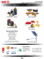
1
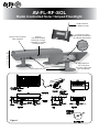
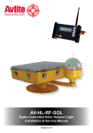
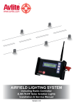
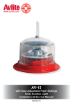
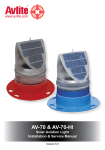
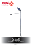
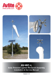
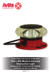
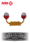
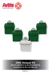
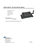
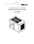
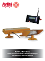
AV-FL-RF-SOL
Radio Controlled Solar Helipad Floodlight
Installation & Service Manual
Version 1.3
AV-FL-RF-SOL
Radio Controlled Solar Helipad Floodlight
Global 2.4GHz
RF Radio control
Large multicrystalline
solar module
Internal
user-replaceable
battery & charge
controller in sealed
compartment
Low Profile - 25cm
Frangible mount
Figure 1
Custom lens optic
designed specifically
for helipad operations
Adjustable tilt
LED luminaire
for even & focused
light distribution
AV-FL-SOL-RF
Radio Controlled Solar Helipad Floodlight
Table of Contents
Introduction................................................................................................................... 4
Technology.................................................................................................................... 4
AV-FL-RF-SOL Model................................................................................................... 5
Assembly & Installation............................................................................................... 8
Assembling the Light & Configuration of Settings.........................................................................................8
TLOF Light Arrangement............................................................................................................................. 11
LED Floodlight Unit Adjustment...................................................................................................................12
Charge Port................................................................................................................. 13
How Does the HLS System Work?............................................................................ 14
Standard Operation Mode.......................................................................................... 14
Best Practice............................................................................................................... 14
Manual Light Activation via External Override Switch........................................... 15
Block Diagram............................................................................................................ 15
Avlite Radio Controller............................................................................................... 16
Assembly & Installation of Radio Controller........................................................... 17
Unpacking Instructions................................................................................................................................17
Initial Inspection...........................................................................................................................................17
Assembling & Charging...............................................................................................................................17
Turning the Unit On.....................................................................................................................................17
Charging the Radio Controller.....................................................................................................................17
Radio Controller Menu............................................................................................... 18
Modes of Operation.....................................................................................................................................18
Light Group..................................................................................................................................................18
Timeout Duration.........................................................................................................................................19
LED Bank Setup..........................................................................................................................................19
Battery Diagnostic.......................................................................................................................................19
Sending Commands....................................................................................................................................19
Using the Radio Control to Activate the Heliport Lighting System (HLS)............ 19
Turn All the Lights ON..................................................................................................................................19
Maintenance & Servicing........................................................................................... 20
Trouble Shooting........................................................................................................ 21
Avlite Light Warranty.................................................................................................. 22
Version No.
Description
Date
Approved
1.0
1.1
1.2
1.3
Manual Launch
Updated spec table
General updates
Assembly & Charge Port
August 2012
January 2013
March 2013
March 2013
S. Turner
J. Dore
A. Groell
A. Groell
Latest products and information available at www.avlite.com
3
AV-FL-SOL-RF
Radio Controlled Solar Helipad Floodlight
Introduction
Congratulations! By choosing to purchase an Avlite light, you have become the
owner of one of the most advanced solar LED aviation lights in the world.
Avlite Systems draws on more than 25 years experience in the design and manufacture of navigation
aids, and particular care has been taken to ensure your light gives years of trouble free service.
As a commitment to producing the highest quality products for our customers, Avlite has been
independently certified as complying with the requirements of ISO 9001:2008 quality management
system.
By taking a few moments to browse through this booklet, you will become familiar with the versatility of
your light, and be able to maximise its operating function.
Please remember to complete the Avlite warranty registration card accompanying your light.
Technology
Avlite Systems is a world-class solar lighting systems manufacturer with a proven
reputation for rapid, innovative, and agile technology solutions designed specifically
for defense, government, civil and humanitarian aid operations in the most remote,
toughest environments.
Electronics
Avlite employs leading in-house electronic engineers in the design and development of software and
related circuitry. All individual electronic components are sourced directly by Avlite procurement staff
ensuring that only the highest quality components are used in our products.
LED Technology
All aviation lights use the latest advancements in LED (Light Emitting Diode) technology as a light
source. The major advantage of LED’s over traditional light sources is well established in that they
typically have an operational life in excess of 100,000 hours, resulting in substantial savings to
maintenance and servicing costs.
Precision Construction
Commitment to investing in the design and construction of injection-moulded parts including optic
lenses, light bases and a range of other components ensures that all Avlite products are of a
consistent and superior quality.
Optical Performance
Avlite manufactures a range of aviation LED lenses moulded from multi-cavity dies. The company has
superior in-house lens manufacturing capabilities to support outstanding optical performance.
Award-winning, Patented Technology
Several United States and Australian patent registrations are held on Avlite’s range of innovative
designs, with other regional patents pending in Canada, United Kingdom and Europe.
Latest products and information available at www.avlite.com
4
AV-FL-SOL-RF
Radio Controlled Solar Helipad Floodlight
AV-FL-RF-SOL Model
Avlite’s solar powered, wireless controlled LED floodlight has been specifically designed
for helipads to provide uniform surface lighting where the TLOF and FATO lights need to be
supplemented with floodlighting. It offers a solar-powered, LED based solution to the ICAO
touchdown and lift-off area perimeter floodlights.
The self-contained solar powered light has an integrated solar and battery system, which means
it can be installed in locations which do not have access to reticulated power - allowing safe
illumination without the need to lay costly cabling or utilise generators.
Solar Power Unit
Figure 2
LED Floodlight Unit
Latest products and information available at www.avlite.com
5
AV-FL-SOL-RF
Radio Controlled Solar Helipad Floodlight
SPECIFICATIONS•*
AV-FL-RF-SOL
Light Characteristics
Light Source
Available colors
LED Life Expectancy (hours)
LED
White, other colors available on request
>100,000
Electrical Characteristics
Voltage (V)
Circuit Protection
Temperature Range
12
Integrated
-40 to 80°C
Solar Characteristics
Solar Module Type
Output (watts)
Solar Module Efficiency (%)
Charging Regulation
Multicrystalline
20
14
Microprocessor controlled
Power Supply
Battery Type
Battery Capacity (Ah)
Nominal Voltage (V)
SLA (Sealed Lead Acid)
18
12
Radio Controlled
Frequency
Compliance
2.4GHz ISM Band
FCC / CE
Physical Characteristics
Body Material
Lens Material
Mounting
Height (mm/inches)
Length (battery housing)(mm/inches)
Length (illuminaire housing)(mm/
inches)
Width (battery housing)(mm/inches)
Width (illuminaire housing)(mm/inches)
Mass (kg/lbs)
Product Life Expectancy
7-stage powder coated aluminium
LEXAN® Polycarbonate – UV stabilized
Frangible mount
250 / 9¾
674 / 26½
406 / 16
332 / 131/8
230 / 9
18.4 / 40½
Up to 12 years
Environmental Factors
Humidity
Icing
Wind Speed
0 to 100%, MIL-STD-810F
22kg per square inch
Up to 160kph
Certifications
CE
Quality Assurance
Waterproof (electronic enclosures)
EN61000-6-3:1997. EN61000-6-1:1997
ISO9001:2008
IP68
Intellectual Property
Trademarks
Warranty *
Options Available
AVLITE® is a registered trademark of Avlite Systems
3 year warranty
• Avlite Pilot Activated Lighting Control
• Mains power
• Specifications subject to change or variation without notice
* Subject to standard terms and conditions
Latest products and information available at www.avlite.com
6
AV-FL-SOL-RF
Radio Controlled Solar Helipad Floodlight
SPECIFICATIONS•*
AV-ALS-RC-2.4-AVMESH
Electrical Characteristics
Range
Temperature Range
Frequency (GHz)
Nominal Voltage (V DC)
Up to 1.4km, AvMesh®
-40 to 80°C
2.4
7.2
Power Supply
Battery Type
Battery Capacity (Ah)
Battery Voltage (V DC)
High grade NiMH - Environmentally friendly
4
7.2
Physical Characteristics
Case Material
Screen
Product Life Expectancy
Anodised aluminium
Backlit
Up to 12 years
Certifications
FCC Approved
CE
Quality Assurance
M100103
EN61000-6-3:1997. EN61000-6-1:1997
ISO9001:2008
Intellectual Property
Trademarks
Warranty *
AVLITE® is a registered trademark of Avlite Systems
1 year warranty
• Specifications subject to change or variation without notice
*Subject to standard terms and conditions
Latest products and information available at www.avlite.com
7
Handheld
controller
and charger in
protective case
AV-FL-SOL-RF
Radio Controlled Solar Helipad Floodlight
Assembly & Installation
The installation of the AV-FL-RF-SOL Solar Aviation Light includes the following steps:•
Unpacking
•
Initial Inspection
•
Assembling the light & configuration of settings
•
Installing the light assembly
Tools required for assembly & installation:•
Hammer
•
6mm Allen Key
Unpacking & Initial Inspection
Unpack all hardware and inspect for damage. If there is any damage, please contact your Avlite Office.
Retain original packing material for possible future use in shipping the AV-FL-RF-SOL .
Assembling the Light & Configuration of Settings
1. Before activating the lights, the lights must be layed out on the helipad in the
location they will be installed.
2. RF lights should always be installed on mounting plates or stakes.
a) LED Floodlight Unit
•
Setup a number1 of concrete pads at equidistant points around the TLOF at ground level. The
concrete pads should have a dimension of approximately 40cm x 40cm with with sufficient depth
depending on soil conditions. NOTE: As an alternative it is possible to use rubber tiles instead of
concrete pads.
•
Embed four bolts. Use the Mount Base as a placing template
•
Make sure the concrete pads are dry and hard before fixing the Mount Base using washers and
screw nuts. Make sure the Mount Base is levelled
•
Fix the Frangible Sleeve (76mm) on top of the Mount Base using the hex socket
•
Fix the LED Floodlight Unit on top of the Frangible Sleeve
•
Point the LED Floodlight Unit into the desired direction2. Make sure the LED Floodlight Unit is just
below 25cm high and levelled
•
Fix the light by tightening the hex sockets at the Frangible Sleeve
1
2
Number of required / planned lights
Please refer to “TLOF Light Arrangement” section of this manual
Latest products and information available at www.avlite.com
8
AV-FL-SOL-RF
Radio Controlled Solar Helipad Floodlight
b) Solar Power Unit
•
Setup another concrete pad next to each LED Floodlight Unit for the Solar Power Units. Make
sure the Solar Power Unit is in close proximity to the LED Floodlight Unit / within cable length. The
concrete pads should have a dimension of approximately 80cm x 40cm with with sufficient depth
depending on soil conditions. Use the Solar Power Unit and Mount Base as a placing template.
NOTE: As an alternative it is possible to use rubber tiles instead of concrete pads.
•
Embed eight bolts. Use the Mount Base as a placing template
•
Make sure the concrete pads are dry and hard before fixing the Mount Bases using washers and
screw nuts. Make sure the Mount Bases are levelled
•
Fix the Frangible Sleeves (98mm) on top of the Mount Bases using the hex socket
•
Fix the Solar Power Unit on top of the Frangible Sleeves
•
Make sure the Solar Power Unit is just below 25cm high and levelled
•
Fix the Solar Power Unit by tightening the hex sockets at the Frangible Sleeve
c) Open the Solar Power Unit
d) Open the electronic compartment inside the Solar Power Unit
e) Connect the cable with the two ring terminals to the battery. Please note the polarity.
f) Connect the LED Floodlight Unit with the Solar Power Unit
g) Fix the antenna underneath the Solar Power Unit
h) Set the Light Group by adjusting the Rotary Switch A on the PCB (please refer to Figure 3)
Rotary switch
Xbee
U.Fl
connector
J3
J5
J1
J2
J4
Figure 3. Rotary switch
Latest products and information available at www.avlite.com
9
AV-FL-SOL-RF
Radio Controlled Solar Helipad Floodlight
i) Determine, to which group, each individual light belongs. E.g., taxiway edge lights = 0, runway
edge lights = 1, obstruction lights = 2, threshold lights = 3, etc... Adjust Rotary Switch A to the
appropriate light group. E.g. 0, 1, or 2
j) Test the operation of the light by using the Radio Controller (see “Using the Radio Control to
activate the HLS System” section of manual for information).
k) Close electronic enclosure and lid of the solar Power Unit. Secure lid with provided bolt
l) Bolt the light into its final location
FRONT VIEW
Solar Panel
Charge port
Connector for LED
Floodlight Unit
Solar Power Unit
Antenna
Frangible Sleeve (98mm)
Mount Base
Ground
Concrete block and in-ground bolds
Recommended size: 40cm x 40cm, depth ~25cm)
Concrete block and in-ground bolds
Recommended size: 40cm x 40cm, depth ~25cm)
400mm
Figure 4. Solar Power Unit
Latest products and information available at www.avlite.com
10
AV-FL-SOL-RF
Radio Controlled Solar Helipad Floodlight
TLOF Light Arrangement
•
Best TLOF area illumination can be archived by an equidistant arrangement of the LED Floodlight
Units around the Helipad.
LEGEND
Solar Power Unit
LED Floodlight Unit
Main Beam
Example of a round TLOF area
with 8 equidistant Flood Lights
pointing towards to the centre point
Example of a squarish TLOF area
with 8 equidistant Flood Lights
Figure 5. Design examples of a round and square TLOF area
with 8 equidistant floodlights
Latest products and information available at www.avlite.com
11
AV-FL-SOL-RF
Radio Controlled Solar Helipad Floodlight
LED Floodlight Unit Adjustment
By using the tilt mechanism each individual LED Floodlight Units can be precisely adjusted. For that
the user has to use the following steps:
•
Loosen the two nut screws at the back of the LED Floodlight Unit (please refer to Figure 6)
•
Adjust the Light Head as required by turning the Tilt Screw Nut. A spring between the LED
Floodlight Unit and the Light Head will provide the required tension
•
After the adjustment secure the tilt / position of the Light Head by tighten the Locking Screw Nut
SIDE VIEW
LED Floodlight Unit
loc Tilt
kin scr
g s ew
re /
w
Tilt mechanism
Light Head
int
t po
Pivo
Frangible Sleeve (76mm)
Mount Base
Ground
Concrete block and in-ground bolds
Recommended size: 40cm x 40cm)
REAR VIEW
LED Floodlight Unit
Cable gland
cking
w / Lo
re
Tilt sc
screw
Tilt mechanism
Light head
int
po
ot
Piv
Frangible Sleeve (76mm)
Concrete block and in-ground bolds
Recommended size: 40cm x 40cm)
Figure 6. Tilt mechanism
Latest products and information available at www.avlite.com
12
AV-FL-SOL-RF
Radio Controlled Solar Helipad Floodlight
Best practice:
For an even light distribution with minimum/no glare please use the following steps:
•
Perform the adjustment at night
•
Switch off all lights except one
•
Go to the opposite light and check for possible glare
•
Adjust the Light Head to minimize any glare as described in “LED Floodlight Unit adjustment”
section of this manual
•
Switch off the adjusted LED Floodlight Unit and perform the tilt adjustment at the next LED
Floodlight Unit until all lights are adjusted as required
For details please refer to Figure 7
LED Floodlight Unit
LED Floodlight Unit
Opposite light
Beam spread
Ground
Figure 7. Beam direction
Charge Port
The Solar Helipad Floodlight has a charge port connector at the front of the Solar Power Box. It enables the
user to connect an external charger/power supply to
•
Assist in keeping batteries charged when in storage
•
Fast-charge for demanding usage profiles
•
Fast-charge for poor solar environments
The external charger can be connected/disconnected at any time and does not affect the normal operation
of the light. Please contact Sealite for possible charger / power supply options.
WARNING: Do not connect the charger of the radio controller to that charge port.
Latest products and information available at www.avlite.com
13
AV-FL-SOL-RF
Radio Controlled Solar Helipad Floodlight
How Does the HLS System Work?
The Avlite HLS System works by using a hand held radio controller to activate and setup an entire heliport,
airfield, airport or air base. The system utilises an embedded R/F module operating in the 2.4Ghz ISM
Band.
The lights can be configured for up to 15 different light groups. This allows the airfield to independently
control different areas, such as multiple runways, taxiways and helipads.
Due to the handheld nature of the Radio Controller, it can be used from most positions in the airfield.
This can allow for easy and efficient inspection or activation of different light groups in the airfield without
affecting other lights.
Standard Operation Mode
Turn ON/OFF the Floodlight by using the radio controller.
Best Practice
It is best to locate the controller as close to the helipad as practicably posible.
The battery inside the light will require extra charge time the following day if the lights are run at HIGH
intensity for more than the recommended time. This can be negated by connecting the lights to an external
power supply (where AV-FL-RF-SOL lights are fitted with an external battery charging port).
If these lights are plugged into an external power supply they can be run at any intensity for any length of
time without depleting the battery.
Latest products and information available at www.avlite.com
14
AV-FL-SOL-RF
Radio Controlled Solar Helipad Floodlight
Manual Light Activation via External Override Switch
The AV-FL-RF-SOL lights (LED Floodlight Unit) are fitted with an external override switch for manual
light operation.
The override switch is for emergency use or in case the radio controller is not operational. This
override switch enables the user to manually turn the light ON and OFF
To activate the AV-HLS-SOL-RF using the override switch:Position 1: The light will switch ON permanently and override any radio controller command.
Position 2: The light will switch OFF and follow the radio controller command.
Block Diagram
Solar Panel
Radio Controller
Regulator
XBee
LED
Relay Card
Override switch
Rotary switch A
-
+
Battery
Figure 8. Block Diagram
Latest products and information available at www.avlite.com
15
AV-FL-SOL-RF
Radio Controlled Solar Helipad Floodlight
Avlite Radio Controller
The Avlite Radio Controller is a compact handheld unit that allows complete control of the heliport
lighting system. The unit allows you to move around the airfield for easy activation, inspection and
testing of the airfield lights. The Avlite Radio Controller works on the 2.4GHz ISM Band using a low
power RF module. The backlit, LCD can be seen during day or night. The straightforward menu makes
the HLS easy to operate.
The Avlite Radio Controller comes standard with an IP68 rated charging plug, omni-directional
antenna and ON/OFF switch and cover.
The Radio Controller and charger come in an IP68 ‘Pelican’ Case to protect it from the harsh
environment to which it may be subjected.
The Avlite Radio Controller can be rack mounted in a standard 19” rack for use with other airfield
electronic equipment such as PALC.
Figure 9. Radio Controller Side View Figure 9. Radio Controller Front View
1 LCD Screen
2 MENU Button
3 SEND Button
4 UP Button
5 DOWN Button
6Antenna
7 Charging Port – IP68 sealed plug. (Charger not shown)
8 RS232 input. (Optional)
Latest products and information available at www.avlite.com
16
AV-FL-SOL-RF
Radio Controlled Solar Helipad Floodlight
Assembly & Installation of Radio Controller
The installation of the Radio Controller includes the following steps:•
•
•
•
Unpacking
Initial Inspection
Assembling & Charging the Radio Controller
Using the Radio Controller
Unpacking instructions
Unpack all hardware and verify container contents in accordance with Fig. 4 & 5. Please contact your
Avlite office if there is any hardware missing.
Initial inspection
Inspect the Radio Controller for damage. If there is any damage, please contact your Avlite office.
Retain original packing material for possible future use.
Assembly & Charging
The Radio Controller can be activated after raising the aerial into the upright position, see Fig 5.
It may be necessary to charge the Radio Controller before use.
Turning the Unit On
To turn the unit on, lift the red missile cover and flick the switch.
The radio controller will take 5 seconds to start up.
Charging the Radio Controller
a. Unscrew the protective cap from the charging port, on the left side of the Radio Controller.
b. Insert the charging terminal into the Radio Controller.
c. Plug the charger into a wall socket and turn the charger on.
d. The light on the charger will flash Green, Orange, Red then back to Orange.
e. The charger has a LED to indicate the charge sequence.
i. Green – Unit is fully charged. The Radio Controller can be left connected in state.
ii. Orange – Unit is charging. The unit will charge for a maximum of 8 hours before automatically
shutting down.
iii. Red – A fault is occurring, please contact Avlite Office.
Latest products and information available at www.avlite.com
17
AV-FL-SOL-RF
Radio Controlled Solar Helipad Floodlight
Radio Controller Menu
This section of the document will provide a short explanation of all the menu screens on the control unit.
Modes of Operation
The operational Mode defines how the light will respond to different environmental conditions & user inputs.
There are three operational modes that can be selected via the controller. ALWAYS ON, STANDBY &
DUSK till DAWN.
ALWAYS ON Operational Mode
The light is ON. The light will be lit both day & night. While the light is in this mode it will only turn off
when the battery drops below the Flat Battery Voltage level. (AV-FL-RF-SOL = 11V)
STANDBY Operational Mode
The light is OFF. While the light is in this mode it will still respond to and pass on commands, sent by
the controller. This mode should be used if the lights are not currently required.
Note: The light is not completely powered down in a manner suitable for storage. If the light is to be
stored in a warehouse or other dark environment the battery connector should be disconnected..
DUSK till DAWN Operational Mode
The light is turned on and off based on the light sensor internal to each light. If the light is in the
darkness, it will turn on. If the light is in daylight, it will turn off.
Note: DUSK till DAWN Operational Mode is currently not applicable for the AV-FL-RF-SOL
Light Group
This menu is used to select the current light group. The light group of each light is selected via rotary
switch A found on the bottom of the circuit board, in the Solar Power Unit. The controller can select any
one of the 10 individual light groups
(0 -> 9) or select all radio lights at once.
Note: The units are set with a light group of 0 in the factory
Latest products and information available at www.avlite.com
18
AV-FL-SOL-RF
Radio Controlled Solar Helipad Floodlight
Timeout Duration
This menu is only visible when the timeout Mode is enabled. This menu is used to select the timeout
duration, the time before the light will switch OFF.
LED Bank Setup
All Avlite HLS systems can have the option of having the lights built with multiple colours, in different LED
banks. This can allow a runway to be changed from Visible to I/R at the press of a button.
The options include VISIBLE & IR.
Note: this menu will not be enabled if the selected operational mode is STANDBY
Battery Diagnostic
Default = Disable
This feature can be used to check the battery voltage in every light in the HLS. The command can be
sent any time and it will not affect the current state of the light. If the light is in STANDBY mode the light
will turn on as shown below and revert to STANDBY mode after the diagnostic has been completed.
•
If the battery voltage is within operational range the light will turn off for 1 second, flash once, then
turn off for 1 second.
•
If the battery voltage is low the light with turn off for 1 second, flash twice, then turn off for 1 second.
Sending Commands
Every time the SEND button is pressed a command is sent containing all the current settings in the Radio
Controller.
The SEND button can be used after changing one setting or after changing multiple settings.
For further information see section under “How does the System Work”.
9.
Using the Radio Control to Activate the
Heliport Lighting System (HLS)
The Radio Controller is very easy to use. Make sure that all the lights in the same Light Group have had the
rotary switches set correctly, see “Assembling the Light” section for details.
Turn All the Lights ON
•
Turn the Radio Controller On
•
Use the arrow keys to adjust the operational Mode to ALWAYS ON
•
Press MENU button once to reach Light Group
•
Set the Light Group to ALL
•
Press SEND button
•
Every radio light within range of the control unit will now turn on.
Latest products and information available at www.avlite.com
19
AV-FL-SOL-RF
Radio Controlled Solar Helipad Floodlight
Maintenance and Servicing
Designed to be maintenance free the AV-FL-RF-SOL light requires minimal attention, though the
following maintenance and servicing information is provided to help ensure the life of your Avlite product.
General Maintenance
a. Cleaning Solar Panels- Occasional cleaning of the solar panels may be required. Using a cloth and
warm soapy water, wipe off any foreign matter before rinsing the panels with fresh water.
b. Battery Check- Inspection of batteries should be performed annually to ensure that the charger,
battery and ancillary electronics are functioning correctly. Using a voltage meter, check that the
correct battery voltage is at least 12 volts under 100mA load for the AV-FL-RF-SOL and ensure all
terminals are clear of foreign matter.
Replacing the Battery in AV-FL-RF-SOL
The user has the ability to change the battery after years of operation.
a. Undo latches and open lid of the solar power unit.
b. Undo battery clamp and detach battery leads.
c. Remove battery from AV-FL-RF-SOL case.
d. Discard old battery in a safe manner.
e. Reattach leads to new battery and then place back into case, fix battery clamps.
f. To test operation of the light, the remote control will need to be used (see “Using the Radio Control
to activate the System” section of manual for information).
Care must be taken to observe the polarity of the battery before the leads are re-connected, and
ensure the replacement battery is correctly fitted. Always recycle old batteries.
AV-FL-RF-SOL Long Term Battery Storage
If the AV-FL-RF-SOL are to be placed in storage for an extended period please follow the below
information.
•
The SLA batteries inside the AV-FL-RF-SOL must always be stored in a fully charged state.
•
Disconnect the battery before placing the light in storage.
•
All batteries will discharge over time and the rate of discharge is dependent on temperature.
•
If the light is being stored in temperatures greater than 30DegC the battery will discharge faster.
•
Please check battery every 2-4 months and recharge if necessary,
Recharging the Battery
Reconnect the battery and place unit in the sun for 2-4 days
Or
Place the light in front of a halogen lamp for 2-3 days (do not place the halogen light too close to the
solar panel or the panel may be overheated)
Latest products and information available at www.avlite.com
20
AV-FL-SOL-RF
Radio Controlled Solar Helipad Floodlight
Trouble Shooting
Problem
Remedy
Light will not activate.
• Ensure internal battery connector in the AV-FL-RF-SOL is connected
• Ensure battery is properly connected
• Ensure battery voltage is above 12volts.
Radio Controller will not turn
on.
• Recharge the battery. The unit can be left attached to the charger for a
constant battery charge.
Latest products and information available at www.avlite.com
21
AV-FL-SOL-RF
Radio Controlled Solar Helipad Floodlight
Avlite Light Warranty V1.1
Activating the Warranty
Upon purchase, the Avlite Systems warranty must be activated for recognition of future claims. To do
this you have two (2) options:
1. Postal Registration
Please complete the Avlite Systems Warranty Registration Card and return to Avlite within 30 days
of your purchase.
2. Online Registration
Please complete the Online Registration Form at; www.avlite.com
Avlite Systems will repair or replace your lantern in the event of electronic failure for a period
of up to three years from the date of purchase.
The unit must be returned to Avlite freight prepaid.
Warranty Terms
1. Avlite Systems warrants that any Avlite aviation products fitted with telemetry equipment including
but not limited to AIS, GSM, GPS or RF (“Telemetry Products”) will be free from defective materials
and workmanship under normal and intended use, subject to the conditions hereinafter set forth,
for a period of twelve (12) months from the date of purchase by the original purchaser.
2. Avlite Systems warrants that any rotationally-moulded products (“Roto-Moulded Products”) and
accessory products (“Accessory Products”) will be free from defective materials and workmanship
under normal and intended use, subject to the conditions hereinafter set forth, for a period of
twelve (12) months from the date of purchase by the original purchaser.
3. Avlite Systems warrants that any Avlite aviation products other than the Telemetry Products, RotoMoulded Products and Accessory Products (“Avlite Products”) will be free from defective materials
and workmanship under normal and intended use, subject to the conditions hereinafter set forth,
for a period of three (3) years from the date of purchase by the original purchaser.
4. Avlite Systems will repair or replace, at Avlite’s sole discretion, any Telemetry Products, RotoMoulded Products, Accessory Products or Avlite Products found to be defective in material and
workmanship in the relevant warranty period so long as the Warranty Conditions (set out below)
are satisfied.
5. If any Telemetry Products or Avlite Products are fitted with a rechargeable battery, Avlite Systems
warrants the battery will be free from defect for a period of one (1) year when used within original
manufacturer’s specifications and instructions.
Warranty Conditions
This Warranty is subject to the following conditions and limitations;
1. The warranty is applicable to lanterns manufactured from 1/1/2009.
2. The warranty is void and inapplicable if:
a. the product has been used or handled other than in accordance with the instructions in the
owner’s manual and any other information or instructions provided to the customer by Avlite;
b. the product has been deliberately abused, or misused, damaged by accident or neglect or in
being transported; or
c. the defect is due to the product being repaired or tampered with by anyone other than Avlite or
authorised Avlite repair personnel.
3. The customer must give Avlite Systems notice of any defect with the product within 30 days of the
customer becoming aware of the defect.
4. Rechargeable batteries have a limited number of charge cycles and may eventually need
to be replaced. Typical battery replacement period is 3-4 years. Long term exposure to high
temperatures will shorten the battery life. Batteries used or stored in a manner inconsistent with
the manufacturer’s specifications and instructions shall not be covered by this warranty.
Latest products and information available at www.avlite.com
22
AV-FL-SOL-RF
Radio Controlled Solar Helipad Floodlight
5. No modifications to the original specifications determined by Avlite shall be made without written
approval of Avlite Systems.
6. Avlite lights can be fitted with 3rd party power supplies and accessories but are covered by the 3rd
party warranty terms and conditions.
7. The product must be packed and returned to Avlite Systems by the customer at his or her
sole expense. Avlite Systems will pay return freight of its choice. A returned product must be
accompanied by a written description of the defect and a photocopy of the original purchase
receipt. This receipt must clearly list model and serial number, the date of purchase, the name and
address of the purchaser and authorised dealer and the price paid by the purchaser. On receipt
of the product, Avlite Systems will assess the product and advise the customer as to whether the
claimed defect is covered by this warranty.
8. Avlite Systems reserves the right to modify the design of any product without obligation to
purchasers of previously manufactured products and to change the prices or specifications of any
product without notice or obligation to any person.
9. Input voltage shall not exceed those recommended for the product.
10. Warranty does not cover damage caused by the incorrect replacement of battery in solar lantern
models.
11. This warranty does not cover any damage or defect caused to any product as a result of water
flooding or any other acts of nature.
12. There are no representations or warranties of any kind by Avlite or any other person who is an
agent, employee, or other representative or affiliate of Avlite, express or implied, with respect to
condition of performance of any product, their merchantability, or fitness for a particular purpose, or
with respect to any other matter relating to any products.
Limitation of Liability
To the extent permitted by section 68A of the Trade Practices Act 1974 (Cth), the liability of Avlite
Systems under this Warranty will be, at the option of Avlite Systems, limited to either the replacement
or repair of any defective product covered by this Warranty. Avlite Systems will not be liable to Buyer
for consequential damages resulting from any defect or deficiencies in accepted items.
Limited to Original Purchaser
This Warranty is for the sole benefit of the original purchaser of the covered product and shall not
extend to any subsequent purchaser of the product.
Miscellaneous
Apart from the specific warranties provided under this warranty, all other express or implied warranties
relating to the above product is hereby excluded to the fullest extent allowable under law. The warranty
does not extend to any lost profits, loss of good will or any indirect, incidental or consequential costs or
damages or losses incurred by the purchaser as a result of any defect with the covered product.
Warrantor
Avlite Systems has authorised distribution in many countries of the world. In each country, the
authorised importing distributor has accepted the responsibility for warranty of products sold by
distributor. Warranty service should normally be obtained from the importing distributor from whom
you purchased your product. In the event of service required beyond the capability of the importer,
Avlite Systems will fulfil the conditions of the warranty. Such product must be returned at the owner’s
expense to the Avlite Systems factory, together with a photocopy of the bill of sale for that product, a
detailed description of the problem, and any information necessary for return shipment.
Information in this manual is subject to change without notice and does not represent a commitment on the part of the vendor.
Avlite products are subject to certain Australian and worldwide patent applications.
Latest products and information available at www.avlite.com
23
AV-FL-SOL-RF
Radio Controlled Solar Helipad Floodlight
Other Avlite Products Available
Solar Aviation Lighting
Helipad Lighting
Obstruction Lighting
Airfield Markers
& Accessories
Typical Applications
• Temporary & permanent
airfield lighting
• Remote, emergency &
defence airfield lighting
• Barricade, hazard &
perimeter lighting
• Helipad lighting
• Obstruction lighting
For a complete list of product compliances
including ICAO & FAA, please contact Avlite today
Area & Sign Lighting
Head Office
Avlite Systems
11 Industrial Drive
Somerville, Vic 3912
Australia
Tel: +61 (0)3 5977 6128
Fax: +61 (0)3 5977 6124
Email: [email protected]
Internet: www.avlite.com
A subsidiary of Sealite Pty Ltd www.sealite.com
Latest products and information available at www.avlite.com
24