1
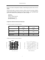
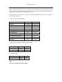
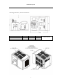
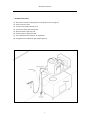
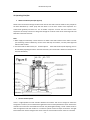
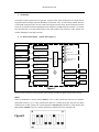
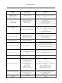
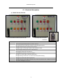
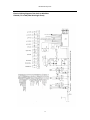
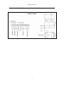
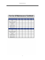
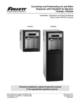
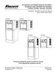
Revised January 2012 FF SERIES OF FLAKE ICE MACHINES (COMPLETE UNIT) SERVICE MANUAL FOR FF0.4 AR & FF0.6 AR MODELS 230v 1 Phase 50HZ (Refrigerant: R404A) Revised January 2012 Table of Contents I. Overview ............................................................................................................................. 4 II. Operation Conditions & Performance Parameters 1. Conditions for Operation of FF Series Scale Ice Machine .............................................................. 4 2. Diagram for Ice Output of Scale Ice Machine ............................................................................... 4 3. Parameters of Scale Ice Machine .................................................................................................. 5 4. Working Pressure (Ambient temperature: 25 )........................................................................... 5 5. Refrigerant Charge ....................................................................................................................... 5 6. Dimensions, Drawings, Air flow & Clearances .............................................................................. 6 III. Packing, Transportation and Installation 1. Packing, Transporting and Storing ................................................................................................ 7 2. Installation ................................................................................................................................... 7 3. Installation Procedures ................................................................................................................. 8 Installation Schematic Diagram for Split Unit ............................................................................... 8 5. Operating Instructions ............................................................................................................... 9 IV. Operating Principles 2. Water Circulation System ........................................................................................................... 10 3. Ice level Control System ........................................................................................................... 10 4. The Gearbox ............................................................................................................................... 11 5. P.C. Board Controlling System ..................................................................................................... 11 V. Maintenance & Trouble Shooting 1. Equipment Maintenance ............................................................................................................ 12 2. Cleaning Procedures ................................................................................................................... 13 3. Trouble Shooting ........................................................................................................................ 14 VI. Electrical Information ..................................................................................................... 15 a) Control Panel ............................................................................................................. 15 b) Electrical Wiring Diagram of the Slice Ice Machine .................................................. 16 c) Timer Control Wiring Diagram .................................................................................. 17 VII. PC Board Explained ..................................................................................................... 18 1. Circuit Board Layout ................................................................................................ 18 a) Ice making machine PC Board layout (back) ...................................................... 18 b) Ice making external indicator small board layout .............................................. 18 c) ice full sensor sensitivity small board layout ...................................................... 19 Revised January 2012 2. Fault Indicator ........................................................................................................... 19 3. Dip Switch .................................................................................................................. 20 a)8‐bit DIP Switch ................................................................................................... 20 b) 4‐bit DIP Switch .................................................................................................. 21 4. Electrical Wiring Diagram .......................................................................................... 22 a) Ice machine PC Board wiring diagram ............................................................... 22 b) Ice Machine external indicator (small board) wiring diagram ........................... 23 c) Ice Making sensor wiring diagram ..................................................................... 23 5.Ice Full Sensor sensitivity and DIP switch settings ..................................................... 24 a)Full sensor sensitivity settings ............................................................................ 24 b) Ice Full sensor sensitivity and adjustment method ........................................... 24 VIII. Grant Timer ........................................................................................................... 25 a)Parts Indentification ............................................................................................ 25 b)Operating Instructions ........................................................................................ 26 c)Specifications ....................................................................................................... 27 IX. Technical Notes ........................................................................................................ 28 X. Service Bulletins… ..................................................................................................... 29 Revised January 2012 I. Overview Read this service manual carefully before installation, troubleshooting and operation of this sub‐zero ice machine. This Service Manual gives an introduction of operation conditions, performance parameters, installation, troubleshooting and operating procedures of FF series sub‐zero ice machines. The ice making system has a vertical, static evaporator with a rotating auger. The machine is equipped with a solid state PC board, which controls and monitors the functionality of the ice machine, indicating: (1) Ice level (2) Water level (3) Motor and gearbox operation (4) Temperature of condenser (5) Level of refrigerant (6) Temperature of evaporator II. Operation Conditions & Performance Parameters 1. Conditions for Operation of FF Scale Ice Machine Minimum Operating Conditions Maximum Operating Conditions 5℃ 46℃ 5℃ 35℃ Water Pressure 0.15MPa 0.5MPa Voltage Variation ‐10% +10% Ambient Temperature Water Temperature Ice output in 24 hrs (kg) 0.4 AR Ambient Temperature Ice output in 24 hrs (kg) Water temperature(℃) 4 Ambient Temperature 2. Diagram for Ice Output of sub Zero Ice Machine Water temperature(℃) Revised January 2012 Note: Daily ice output is directly related to the air temperature at the condenser and inlet water temperature. In order to keep optimum operation performance of FF series sub‐zero ice machines maintenance must be performed on a regular basis as per service manual section V. Model description: FF×××AR model is a complete unit including refrigeration system ready for connection to power, water and drainage. 3. Parameters of Sub Zero Ice Machine Model FF0.4AR FF0.6AR Voltage (v) 230V/50HZ/1N 230V/50HZ/1N Current (A) 14.5 18 Condensing Type Air cooled Air cooled Compressor (HP) 2 3 Power (W) 3100 3900 Wiring Size (mm2) 3x2.5 3x2.5 Water Usage L/h 17 25 Water Inlet (outside thread) ¾” ¾” Drain (outside diameter mm) 21 21 Weight (kg) 180 250 4. Working Pressure (Ambient temperature 25℃, R404A) Model FF0.4AR FF0.6AR Discharge Pressure 1850Kpa 1850Kpa Suction Pressure 200Kpa 200Kpa 5. Refrigerant Charge Model FF0.4AR FF0.6AR Refrigerant Charge (g) 2000g 3200g Note: This may vary if machine parameters change 5 Revised January 2012 6. Drawings, Dimensions, Air flow and Clearances D Model FF0.4AR FF0.6AR W(mm) 1090 1250 D(mm) 700 750 H(mm) 720 820 External dimensions incl stainless steel cover 6 Revised January 2012 Packing/ Transportation/ Storing and Installation 1. A. B. C. 2. A. B. C. D. E. Packing, Transportation and Storing The ice machine is packed in plywood. Beware of collision, vibration, tilting, inversion, etc. in transportation and storage. Ice machine should be kept below 40C, dry, and well‐ventilated Before you begin: Check your paperwork to determine the model received matches your order. After uncrating and removing all packing material, inspect equipment for any shipping damage. Check whether all connections (water system, refrigerant system, etc.), electrical connections (wires, PC board, etc.) and mechanical system are in good condition. Installation (See figure 2) Electrical connections must comply with local standards and requirements on the rating plate of the machine. An isolation switch must be installed Constant water supply (Pressure between 0.15 kPa to 0.5 MPa) and stop cock shall be supplied within 1 mtr of the ice machine. Suitable drainage point shall be within 1 mtr of ice machine. Two separate water drainage lines shall be required for draining the ice machine and the ice storage bin. The ice machine shall not be placed (1) without suitable ventilation; (2) next to heat sources; or (3) outdoors. To ensure ice quality a water filter should be installed in icemaker inlet water line. 7 Revised January 2012 3. Installation Procedures (1) Place the ice machine on appropriate ice storage bin and fix. See figure 2. (2) Ensure machine is level (3) Connect water supply with stop cock. (4) Connect the drains with sufficient fall. (5) Open the water supply stop cock. (6) Connect power to approved outlet. (7) Use a qualified service technician for installation. (8) See figure 3 for installation of split unit.(See figure 3) 8 Revised January 2012 Operating Instructions (1) To start up After the machine has been installed as per instructions, plug in and switch on. The indicator light A (the green light) will come on. Turn the Manual “Off/Auto” to “manual on” position (turn the switch in a clockwise direction) and the machine will be on 5 minutes’ delay (the fourth red light of the second row of the control box will be flashing). After 5 minutes’ delay, the machine will start. (2) To stop the machine Turn off the Manual “Off/Auto” switch and the machine will stop. Each time you turn on the “On/Off” switch and start the machine, the machine will begin to run automatically after 5 minutes’ delay. A. The 5 indicator lights in the second row on the front panel of the control box monitor the following: Note: 1. Reasons for high condenser temperature: faulty fan motor; blocked condenser; high ambient temperature; damaged condenser, faulty temperature sensor or P.C board. 2. Reasons for high evaporator temperature: check refrigeration system, faulty evaporator temperature sensor or P.C board. B. The third red light in the first row (C) on the front panel of the control box will be on if the discharge pressure of the compressor is higher than the specified value (factory set) or if the suction pressure is lower than the specified value (factory set). Please identify causes and rectify before resetting the machine manually. C. In event of emergency, push the “Emergency Shutdown” button to stop the machine. 9 Revised January 2012 IV. Operating Principles 1. Water Circulation System (See figure 6) Water enters the machine through the float valve and into the water reservoir. Water is then pumped to the water distributor by a water pump and then flows on to the inner surface of the evaporator. It is cooled down gradually and forms ice. The ice blades scrape the ice from the inner surface of the evaporator and it drops into the ice storage bin through the ice Shute. Some of the remaining water will flow back to the water reservoir. Note: a. Water supply is monitored by a sensor. If there is no water in the water reservoir or the water is too soft (not containing mineral substances), the P.C. board will stop the machine, and the yellow light will indicate a lack of water. b. The water level has been factory set. Do NOT adjust it. If the water level requires adjusting, this can be achieved by adjusting the valve in the water reservoir. (The correct level is 26mm from the bottom of the water distributor) 2. Ice Level Control System There is a light‐operated ice level controller between the machine and the ice storage bin. When the storage bin is full of ice, the ice will break the light beam of the ice level photoelectric sensor and then the red LED in the center of P.C. board will be turned off. The yellow light indicating “ice full” will be turned on after the light beam has been broken for a continuous period of time and stops the machine. The light beam will be reset and the red light in the center of the P.C. board will be turned on if the ice is removed. 10 Revised January 2012 3. The Gearbox This system includes a gear motor and gear box. The gear motor drives the gearbox. The output shaft of the gearbox drives the auger and water distributor at a speed of 2 rpm. In case of wrong rotation direction or low speed of the gear motor, the sensor will send a signal to the P.C. board, which will stop the machine. Causes of the trouble should be identified and fault should be rectified before the machine is re‐started. Press the Reset key or put the On/Off switch at the "OFF" position first and then to "ON" position, the machine will begin to work again normally. 4. P.C. Board Control System ( please refer to figure 7 ) Power display Ice level sensor Ice level circuit 2 Motor rotation Motor rotation sensor signal circuit 3 Evaporator temperature High Evaporator temperature sensor circuit 4 Micro-processor Water level Water level sensor circuit 1 Bin Full Water level High Condenser temperature Low rotation speed and high evaporator temperature High‐temperature protection Compressor circuit 5 circuit 9 Compressor contactor Condenser temperature Low‐temperature protection Gear motor sensor circuit 6 circuit 10 Fan cycle Fan cycle circuit 7 circuit 11 Gear motor Fan motor Figure 7 The P.C. board controls the whole operation of the machine according to signals sent by various sensors. Notice: There are 8 switches on the P.C. board. Switch 1: if it is in "ON" position there will be no 5 minutes' delay after start‐up; if it is in "OFF" position there will be a 5 minute delay after start‐up. The switch should be set at "OFF" position for normal operation. Switch 2 & 3: should be in "ON" position. DO NOT TOUCH. Switch 6 in the “On” position provides an audible fault alarm; (see figure 8). Figure 8 11 Revised January 2012 V. Maintenance & Trouble‐shooting 1. Equipment Maintenance Warning: No cleaning or maintenance shall be carried out on the machine prior, to carrying out correct isolation procedures to isolate the machine from the power and water supply. Coast Distributors recommends the use of PPE when carrying out a service or maintenance on either the ITS, BIN, or Grant ice machine. A. Daily procedures For continued ice quality, check the following. Nothing is allowed to be stored in the ice storage bin. Always keep the bin door closed and the ice paddle clean. Check for ice clumping, if clumping is present clear the ice or melt the ice with warm water. To protect the machine from any damage, please pay attention to the items stated below: Don’t turn off the water supply when machine is operating. Open/close the storage bin door gently and never kick or jerk the door. Never stack anything on the top of ice storage bin or ice machine and maintain minimum clearances for correct air circulation. B. Regular cleaning & maintenance (monthly) Users should adopt a regular cleaning and maintenance program in accordance with the surrounding environmental conditions. In order to ensure proper performance and sanitary condition, the following regular maintenance should be carried out, (at an interval of about one month). Clean the inside walls of the ice storage bin with detergent and warm water. Sanitize the bin surfaces, internally then flush with warm water. Clean the external surfaces of the bin and ice machine with a soft cloth and stainless steel cleaner. Cleaning the Condenser Condenser coil should be checked and cleaned if required at monthly intervals. C. Regular cleaning & maintenance (6 monthly) Qualified service personal only should carry out the following maintenance and checks. Carry out correct isolation procedures prior to doing any of the following. Visually check for signs of oil leaks around the speed reducer gear box. Check and clean if necessary the condenser coil. Remove the speed reducer and check for play in the top bearing. Remove the 2 plastic top covers on the evaporator and check the following. Check the water distribution tray and distribution tubes for foreign materials and restrictions clean if required. Remove the water distribution tray and check the ice blade top and bottom bearings for play, replace if required. Check bottom bearing for movement and or play, replace if required. Check bottom water catchment tray for signs of damage or cracks, replace if required. Check bottom evaporator water trough for foreign material, clean if required. Reassemble and check all bolts for tightness. Check water strainer in inlet to the water reservoir for dirt or foreign materials. 12 Revised January 2012 . 2. Cleaning Procedures 1. Carry out correct isolation procedures and test unit for power loss. 2. Isolate the water supply to the machine. 3. Remove and replace the water filter cartridge and purge approx 4ltrs of water through filter. 4. Carry out visual inspection of the unit. 5. Remove the black top plastic cover on the evaporator. 6. Check condition of water distributor and tubes. 7. Check condition of plastic water pan at the bottom of evaporator. 8. Check water float operation and water level. Adjust or replace if required. 9. Check water trough for foreign matter and clear if required. 10. Check water reservoir. 11. Check for any water leaks. 12. Isolate the refrigeration circuit, so as no refrigeration of the evaporator occurs this can be done by either separating the compressor overload from the contactor ( all AR models )or isolating the power to the liquid line solenoid valve coil on (all FFE models) 13. Drain the water from the water reservoir via the drain tap on rear of tank and measure water quantity. This is to ascertain how much cleaning solution is required. 14. Make up correct amount of cleaning solution as per manufacturer’s directions and empty solution into the water reservoir. 15. Re‐energize the power to the machine and set dip switch 1of 8 (time delay override) to the up position and turn the machine on. 16. Run the machine for the correct indicated time as per chemical manufactures directions (usually 20 min). During this time the machine will fault on high evaporator temp alarm (10 min delay) and will require a reset to start the alarm delay over again. 17. Once the cleaning time has elapsed, turn unit off and drain the water and flush the system 4 times. 18. Clean the bin and flush / check the drain. 19. Drain the water from the water reservoir via rear drain tap. 20. Mix up and add sanitizer solution to the system, turn unit back on. 21. Sanitize bin. 22. Follow the manufactures directions on the sanitization procedure. 23. After 10 min reset and wait another 10 min. Once this time has elapsed, turn the unit off and drain the water and flush the system 4 times. 24. Carry out correct isolation procedure and test unit for power. 25. Re‐connect the compressor overload or solenoid valve coil power. 26. Reset the delay timer dip switch (no 1 of 8) back to the off position “Down”. 27. Clean the unit, condenser and covers where fitted. 28. Turn the water back on to the machine. 29. Re‐energize the power and turn the machine on. 30. Check operation of unit. 31. Check Auto/Off/Man operation and time clock setting. 32. Check bin legs, door and trolleys where applicable. The above procedure takes approx 1.5 to 2 hrs depending on, if is on a slope front bin or a Follett ITS. 13 Revised January 2012 3. Trouble Shooting Symptom Possible Causes Solution Ice Machine not running. Power supply turned off Check power lead is plugged in and turned on. Check circuit 1.Power supply light is off breaker. Rotate switch clockwise to reset. 2.PC Board light is off Still no PC Board Light Emergency button pressed. Turn switch to Auto On/Off or Man/off/Auto switch off. Turn switch to Manual, if PC Board light comes on then timer Machine off on timer. requires adjusting or setting. If PC Board power light still stays off check F1 fuse on PC Board. Adjust bin full sensitivity via adjustment pot, (5 LED bars on‐ 5 3. Bin Full light is on but the bin is empty. off) Bin full sensor requires sensitivity adjusting If the LED is on, machine should be on time delay, (time delay Check bin full led in middle of PC Board is on light flashing) If not on time delay replace PC Board. 4. Water shortage light is ON. 5. Compressor failure light on. Blocked water filter cartridge. Replace water filter cartridge / bypass cartridge to test Blocked water strainer at inlet. operation. Clean strainer. Water float jammed or broken. Repair or replace water float. Check compressor, supply voltage, compressor electrics. Compressor overload tripped. Replace faulty components as required. LP tripped, check gas charge, TX Valve, Liquid line solenoid valve. Replace faulty components as required. 6. Low or High pressure light on. HP tripped, check condenser coil, air flow, condenser fan motor, LP/HP tripped. clean coil or replace fan motor if required. Repair gas leak and regas system with correct gas charge. 7. Time delay / hi cond light on. 8. Time delay light flashing. Liquid line reached 55 deg C or ambient lower Dirty condenser, Too high/ too low ambient, faulty sensor. Clean condenser, rectify ambient conditions (ventilation) than 4 deg C Replace faulty sensor. Unit on 5 min time delay No action required. Reamer motor RPM dropped by more than 9. Low rotation / Hi Evap light on. Check Hz. 7%. Hertz lower than 45Hz. Speed reducer reversed direction Check motor capacitor, replace if required. Ice cutting blade incorrect spacing. Check ice blade spacing 0.3mm adjust if required. Replace worn Worn bearings. bearings. Speed reducer faulty. Replace speed reducer motor / box Speed reducer low on oil. Replace speed reducer motor / box Speed reducer motor faulty. Replace speed reducer motor / box. Suction line out of evaporator failed to reach Check gas charge, TX Valve, liquid line solenoid valve, ‐1degC after 10 min from start up or reached Refrigeration not working, rectify refrigeration problem. ‐30degC for a period of 5min. Check water flow over evaporator, 10. Low rotation / Hi Evap light flashing. Faulty sensor. 11. No power on timer transformer (green LED off) Replace faulty sensor Check transformer, timer relay and timer, replace faulty parts as Blown RD4 fuse required. 14 Revised January 2012 V I . Electrical Information a) GRANT FF0.4AR / FF0.6AR. Control Panel on B400 Bin with Manual On/Off switch fitted Manual On/Off switch on ITS system is located on Bin. LOCATION A B C D E F G H FUNCTION Green power light indicates power to machine when lit Red compressor failure indicates compressor overload tripped when lit Red light indicates high or low pressure trip when lit Emergency stop – Push to stop machine, twist clockwise to reset Green P.C. light indicates power to P.C. Board when lit Orange light indicates bin is full when lit Orange light ON indicates no water to machine Red light on indicates high condensing temperature Red light flashing indicates unit on 5 minute time delay before starting J Red light on indicates low rotation speed fault Red light flashing indicates high evaporator fault, suction line failed to reach 1 degree C for 10 min Or reached ‐30 degrees C for 5 min. 15 Revised January 2012 Electrical Wiring Diagram of the Scale Ice Machines FF0.4AR / FF 0.6 AR (240v 50Hz Single Phase) 16 Revised January 2012 d) Timer Control Wiring Diagram FF0.4AR / FF0.6AR 17 Revised January 2012 V II PC BOARD EXPLAINED 1、Ice making PC board layout (back) b) Ice making external indicator small board layout 18 Revised January 2012 c) Ice full sensor sensitivity small board layout 2. Fault Indicator * When the power frequency is lower than 45Hz more than five seconds all the indicator lights flash at the same time 19 Revised January 2012 3. Dip Switch a). 8‐bit DIP switch (Attention: Please press reset button before resetting DIP switch.) 1 (ON): Cancel starting up delay. 2,3 (ON):Select sub zero ice machine’s ice-full sensor 4 (OFF): Not Used 5 (OFF): Select 1440RPM model. 6 (ON): Turn on the buzzer. Warning: Please press reset button before resetting DIP switch Start up delay function on Cancel the buzzer (off) Cancel start up delay function Open the buzzer (on) Select 1440RPM model Cancel the test parameters (factory) Select sub zero ice machines ice full sensor Open the test parameters (factory) Eight‐bit DIP switches on the centre of the PC board (Figure 3‐1) are from left to right. Override is when dip switch is in the on position. The function of the first bit DIP switch: Selects the starting up delay function. When the first bit DIP switch is on, the unit will start up with no delay. (This feature is used during maintenance of the ice machine). When dip switch is in the off position the unit will have a five minute delay, which is to ensure the sensor is clear of ice. The function of the second and third bit DIP switch: Select the ice full sensor to suit ice type. To select sub zero machine ice‐full sensor, both dip switch`s 2 and 3 are in the on position. The function of the fourth bit DIP switch: DIP switch invalid. The function of the fifth bit DIP switch: Selects the models of the gear motor. 1440 RPM when the dip switch is in the off position (the location of switch has been set up at the factory, the user should not be touched) 20 Revised January 2012 The function of the sixth bit DIP switch: Selects the buzzer alarm. When the sixth bit DIP switch is in the on position, the buzzer will alarm when a fault is triggered, in contrast, the buzzer is silent when the dip switch is in the off position. The function of the seventh bit DIP switch: DIP switch is invalid. The function of the eighth bit DIP switch: Selects the test parameters. (Testing the PC board design parameters at factory).( the switch has been set off at the factory) b) 4‐bit DIP switch (Warning: Please press reset button before resetting DIP switch.) Factory Settings 1 (ON) Cancel low rotating speed protection 2 (ON) Cancel condensing temperature protection 3 (ON) Cancel evaporation temperature protection 4 (ON) Cancel ice full protection Turns on the low‐rotating speed fault protection Turns on the evaporating temperature protection Cancels the low‐rotating speed fault protection Cancels the evaporator temperature protection Turns on the ice full protection Turns on the condensing temperature protection Cancels the ice full protection Cancels the condensing temperature protection Four‐bit DIP switches on the center of the PC board (Figure 3‐2) are in order from left to right. The function off the 4 dip switch’s are to bypass any of the 4 sensors so the machine can continue to function until the fault is rectified. When a bypass is activated the fault light for that sensor will continue to be activated until the fault is rectified and the unit is reset. 21 Revised January 2012 4.Electrical wiring diagram a). Ice machine PC board wiring diagram Ice making PC board layout (front) figure 4‐1 22 Revised January 2012 Power Indicator Ice full fault indicator Water shortage fault indicator Condenser fault indicator / delay indicator Rotating speed fault indicator / evaporator Fault Indicator b) Ice machine external indicator (small board) wiring diagram c) Ice making sensor wiring diagram 23 Revised January 2012 5.Ice full sensor sensitivity and DIP switch settings a)、Ice full sensor sensitivity settings Flake ice machine:XB70—XB550 model 5 indicator. Sub Zero machine:PB0.4F/A—PB50F/A model 5 indicator. b) Setup of ice full sensor sensitivity Ice full sensor sensitivity may diminish after a certain period of time. At this time, It can be adjusted by the ice full sensitivity resistor on the PC board. Clockwise rotation will increase the number of lights; ice full sensor sensitivity will increase accordingly. Anti clockwise rotation will decrease sensitivity and decrease the number of lights The LED 1 next to the 8 dip switches is the sensitivity indicator, when the LED is lit the bin is empty, when the LED is off the bin is full. 24 Revised January 2012 Grant Timer with remote switch The Grant unit can be fitted with a remote switch and timer, the function of this is twofold. As the electrical control board is placed on the unit, this can make access to the factory fitted switches difficult. The remote switch allows the ON/OFF/AUTO switch to be placed in an easily accessible location, such as when the unit is placed on a large ice bin or transport system i.e. Follet ITS or DEV. The timer is designed to reduce the ice clumping found with storing scale type ice for long periods. The theory is to supply only the ice needed for the demand, an example would be: Grant one ton FFE on a Follett DEV. (ice bin) Customer requires 400 kg of ice at 7am and 200kg at 4pm. Timer will require to be set from 10pm to 7am and 11am to 4pm Grant 1 ton FFE = 1000kg/24hrs = 41kg/1hr 400kg will require the unit to run for 10hours. 200kg will require the unit to run for 5hours. Of course this is only an example and every application will vary but the principal is the same, it will be up to the technician to consult with the customer and set timer to suit their needs. With the timer set up correctly, the machine will produce Ice on demand and prevent clumping of ice in the storage bin. a) Parts Identification 25 Revised January 2012 b) Operating Instructions Before turning power ON, Check that your unit conforms to the operating voltage. If the unit has not been in operation for a long period the battery may have discharged and may not work immediately. Connect the unit and switch power source on, wait for approximately ten minutes before setting the timer. Full power reserve is built up after approximately 72 hours. 1. Setting the timer Set the setting pin between the desired times to the left or right of the dial. Set the setting pin to the right of the dial; ON position If the setting pin is set to the ON position continuously, it will continue only for the number of setting pins x 15 minutes. Set the setting pin to the right until a click is heard Set the setting pin to the left of the dial; OFF position 2. Adjust the present time Turn the dial until the index is on the current time 3. Set the manual switch: Use this switch to select either ON or OFF in manual or ON/OFF in the operation program. “Auto”; output is turned ON and OFF according to the set program Manual “ON”; output is turned ON irrespective of the program (Use this mode for test operation) Manual “OFF”; output is turned OFF irrespective of the program. After completing test operation set the manual switch to “AUTO” 26 Revised January 2012 c) Specifications Rated Voltage 240VAC Voltage tolerance 220‐260VAC Frequency 50hz Power consumption 1w Drive Method Quartz controlled stepping motor Cycle 24 hours Time precision +/‐3 sec/ day at 22degrees Celcius Circuit Separate Switch construction SPST Manual ON/OFF ON/AUTO/OFF switch Load Capacity Resistive Load 16A Incandescant lamp 10A Inductive 12A Motor 220v AC 1500W Present Time Setting Setting Turn dial until the index is at the current time ON/OFF program setting 15 minutes Minimum Unit 15 minutes Minimum interval 15 minutes No of ON/OFF operation 96 operations Working reserve time 72 hours Ambient temperature ‐10 degrees celcius ~ +50 degrees celcius Ambient humidity Max 85% Weight 85g 27 Revised January 2012 d) IX . Technical Notes 1. All PC boards after November 2009 will be the bypass model which will allow all sensors to be bypassed for diagnostic purposes. 2. All Grant ice machines up to 10 ton use the same PC board. 3. All grant ice machines 10 ton and over use a PLC. 4. All the old style PC boards have no bypass on any faults except by bridging using the correct ohm resister. 5. Bin full sensor can be bypassed by bridging terminals 2 and 3. 6. All sensors can be bypassed with the correct resister. 7. Low temp sensor can be bypassed with a 10 ohm resister. 8. High condenser temp sensor can be bypassed with a 91 ohm resister. 9. Gear motor speed sensor cannot be bypassed. 10. The square blue potentiometer on the PC board is to set/adjust the sensitivity of the bin full sensor. A correct setting is 5 lights on the small circuit card on the front of the board. If the sensitivity is set to high the sensor can burn out. 11. Speed sensor operates at 1440rpm with a 7% differential. 12. Speed of the gearbox is governed by the hertz and should be checked on every installation. 13. Hertz under 45 will cause low rotation fault. 14. Phase fail control requires a voltage of not less than 380 or greater than 450 volts, but can be set at 10% lower to get out of trouble but is not recommended. 15. Scraper must always be set at 0.3mm off evaporator shell, use a set of feeler gauges. 16. Incorrect ice thickness will trip speed sensor and cause shuddering. 17. If gearbox / scrapper shuddering occur water flow is too great and should be reduced and or TX valve may need adjusting. 18. TX feed can be checked by ice formation on evaporator, i.e. ice forming lines in evaporator increase TX feed. 19. The core dryer fitted to the suction line has no core fitted; the dryer is there for quality control at the factory and is removed after testing. 28 Revised January 2012 X. Service Bulletins Coast Distributors CD series Water Filters Coast tip of the week: Blocked water filter bypass If you need to bypass the water filter in an emergency you can carry out the following to get you out of trouble until you can replace the cartridge. 1. Isolate water to filter 2. Remove filter cartridge 3. Remove small O ring 4. Re‐install filter cartridge 5. Turn water back on By caring out the above, this bypasses the cartridge and allows water to flow to your machine. NOTE: return and replace the filter cartridge as soon as possible 29 Revised January 2012 Water regulating valve If there is water dripping or flowing into the bin from under the evaporator, check the water flow over the evaporator. Ball float adjustment under Water flow regulator valve To adjust the water flow so as not to overflow the drain catchment tray, adjust this valve slowly to regulate the water flow. If the flow is too high, the water overflows the drain tray. If the flow is insufficient there will be little ice production. 30 Revised January 2012 31 Revised January 2012 1800 688 590 Ph: 02 9524 1234 Fax: 02 9524 0968 Email: [email protected] Web: www.coastdistributors.com.au 32