1
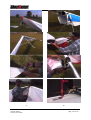
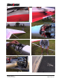
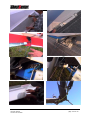
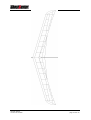
Service Manual
Version: 22.12.1999
Flight Design International
Sielminger Str. 65 D-70771 LeinfeldenEchterdingen
www.flightdesign.com [email protected]
Service manual
Version 19.01.2000
1. Glider description ______________________________________________ 1
2. Transporting the GHOSTBUSTER__________________________________ 1
3. Set up and breakdown___________________________________________ 1
4. Flying Characteristic of the GHOSTBUSTER_________________________ 4
4.1.
Launching ________________________________________________ 4
4.2.
Flying the GHOSTBUSTER___________________________________ 4
4.3.
Thermalling _______________________________________________ 5
4.4.
Landing the GHOSTBUSTER _________________________________ 5
4.5.
Winch towing _____________________________________________ 6
4.6.
UL-towing ________________________________________________ 6
5. Maintenance __________________________________________________ 6
5.1.
Adjustment of the control cables _______________________________ 6
5.2.
Adjustment and function of the stopper rope ______________________ 7
5.3.
Adjustment of the stopper rope ________________________________ 7
5.4.
Replacement of the spoiler ropes ______________________________ 7
5.5.
Checking the rope pulley _____________________________________ 7
5.6.
Check of the ribs and rib connections ___________________________ 7
5.7.
Rib No.8 and diagonal rib ____________________________________ 7
5.8.
Main bolt and belt connection _________________________________ 7
5.9.
Nose fitting _______________________________________________ 8
5.10. D - Spar _________________________________________________ 8
5.11. Rope connection at the ribs and the tip tube ______________________ 8
5.12. Rope connection at the flap ___________________________________ 8
5.13. Restoring rubber of the flap ___________________________________ 8
5.14. Sail _____________________________________________________ 8
6. Limits of usage ________________________________________________ 8
7. Technical data _________________________________________________ 9
8. DHV - classification _____________________________________________ 9
Apendix: set up pictures __________________________________________ 12
Service manual
Version 19.01.2000
1.
Glider description
Footlaunchable Hang Glider FAI class 2 with cantilevered wings built primarily with
carbon fibre.
Note: The GHOSTBUSTER is certified only for solo flights.
2.
Transporting the GHOSTBUSTER
-by car
As the spar is out of carbon fibre it is quite susceptible to punctual load. In the case of
car top mounting a well-padded surface of sufficient length should be used to lay
down the glider, e.g. a ladder with several padded rungs. If there are only two
supporting points (roof rack) they should each be padded approx. 10 cm wide to
distribute the load. It is recommendable to adjust the straps only as tight as
necessary and not to place them on but next to another to get a bigger supporting
area.
The GHOSTBUSTER should be mounted with the control bar bracket (zipper on the
bag) facing upwards. Apart from that we recommend to use a water proof bag to
keep the GHOSTBUSTER dry and to protect it against salt (from icy roads). As the
sandwich construction of the spar, the spoiler and the flaps absorb humidity, and if
the GHOSTBUSTER gets wet anyhow it must be dried immediately to prevent it
becoming mouldy and the metal parts to corrode.
-by cable cars / railway / mountain railway
Actually, the same applies for cable cars. Punctual load on the spar should be
avoided. Some strips of foam material (e.g. isolating jacket) can be used to protect
the glider. If nothing else is at hand your coat would serve well, too.
3.
Set up and Breakdown
Setup
1. Attach the control bar to the uprights.
2. Flip the GHOSTBUSTER upright and rest it on the control bar. Take care not to
hold the glider at the nose turnbuckle as it is not made for bending moments.
(pict. 1)
3. Turn the nose turnbuckle inside out. If the wings are spread out with the nose
turnbuckle inside, the nose tube or the spar may be damaged. Take the
nose and keel tubes and the diagonal ribs out of the D-spar (pict.2).
4. Spread the wings until the keel tube (without the lengthening piece) touches the
ground (pict.3). Especially during the first times of setting the GHOSTBUSTER
up this should be done carefully, for it is the only way to find out and to avoid
mistakes in the order of set up and break down without damaging the glider.
5. Insert the diagonal ribs and push them until they reach the end of the socket and
tension with the lever(pict. 4+5). Pay attention with the right and left side.
6. Link the sail with the keel. If necessary lift the spar a bit back in order to be able
to hang up the hooks (middle of the sail) at the corresponding fitting at the keel
(pict. 6) then zip up the top and the bottom zipper. (pict. 7)
7. The ribs should fall back into the sail.
Service manual
Version 19.01.2000
page 1 from 15
8. Now you have to insert the very outside rib into the corresponding fixture in the
spar (pict. 8). Afterwards fix the sail with the loops at the ribs: Open the “Velcro“
strap at the trailing edge, clap out the ribs and tighten them securing the bottom
and the upper sail loop around the notched end of the rib(pict. 9+10). Should you
notice that one rib is not already clapped out, do it first. Get into the sail with your
hand at the opened end of the “Velcro“ and help it.
9. Spread the wings all the way it is possible. Make sure that the trailing edge is
smooth. Especially after an inspection where the “Velcro“ had to be opened
completely, it may happen that the sail is uneven. If this is the case, the “Velcro“
linking top and bottom sail has to be removed and fastened once more after
having finished with point 11. (pict. 11)
10. Hang up the nose turnbuckle at the bolt (pict. 12) and tighten while pushing the
nose somewhat carefully backside down to the keel tube (pict. 13), after
completely in position secure it with the quick pin.
11. Now fix the following points: rear end of the keel tube, front wire, nose tube and
nose cone (pict. 14+15)
12. Push the bolt of the spoiler lever through the hole in the spoiler and secure the
safety pin, after that fix the “Velcro“ ( pict. 16+17).
13. Insert the flap pin in the fourth rib trailing edge hole. Open the security pin of the
second axle of the flap and hold it open. Position all axles taking care that they
are between the flap tracks in each rib. Insert and secure the second axle
trough the white guide in the third rib, now the flap can stand by it’s own. At the
root of the flap near the keel, open the pulling hook and fix it in the top of the
metal trail, after that insert the end of the rod bearing into the hole of the sail
hooks and secure it with the lock pin. (pict. 18, 19, 20, 21 +22). Afterwards insert
the quick pin at the trailing edge of the flap. With the second flap you proceed the
same way. Important: After fixing each flap, put your finger at the quick pin block
and perform a flap retraction test. This is important to be sure that the flap track is
clear of the battens ropes and that the flap is not jammed under the ribs.
14. Fix the wing tip fairings. The easiest way is fitting the nose of the fairing and then
adjusting the rear part.(pict. 23)
15. Now thread both the flap ropes through the clamps at the base tube and check
the flap operation again. Pull each rope to be sure that the operating cables are
working fine inside the glider. Pay attention to only operate one cable when the
other is totally loose.
15. Fix the control cables of the spoiler and don’t forget to fix the security ring in
the base tube quick pin (pict. 24).
16. Pull the flap rope for approx. 11 cm for a 15º flap deflection for take-off.
Check before every launching:
_ Repeated check of all links of the set up glider (safety rings and split-pins etc.)
_ Make sure the flaps are fully functional (check all positions, as well as the ribs in all
of the seven joining angles).
_ Examine the spoilers’ deflection by moving the trapeze (about 80º deflection).
_ The very outside rib (R8) should be positioned between diagonal rib and the rib
positioned next to it. Make sure that the two metal pins of the rib ends are inserted
at the PVC inserts at the spar wall (pict. 9).
Breakdown
Service manual
Version 19.01.2000
page 2 from 15
Breakdown of the GHOSTBUSTER is simply the reverse of the set up procedure. But
make sure you observe the following points:
_ Detach the spoiler wire before you fold the wings in.
_ The wing tip fairing, the flap and spoiler have to be removed before releasing the
nose fitting
_ Make sure you fold the sail in the area of the spar link the way it can not damage
the zipper when folding in the spars (Pull the top sail up and fold the bottom sail
in). At the zipper the upper sail should not be laid down between the spars. The
zipper has to be fold once whereas the pusher of the zipper has to be pushed to
the trailing edge.
_ When dismantling the spoiler, be careful that the spoiler lever does not spring back
against the rib.
_ Make sure you pack all extra parts in the bag the way no damages may be caused
by your car’s rack, the straps or any other mechanical influence upon the glider.
NOTE:
_ Never leave the diagonal ribs in position with the leading edge laying in the ground
whilst the sail is not fixed at them. The sail prevents an outward movement that in
extreme cases could damage the tip area.
_ Never loosen or tighten the glider before removing the end of the keel. You can
damage your turnbuckle otherwise.
_ When setting the glider up or breaking it down make sure the spar is staying firmly
without any rear end of a rib scraping the ground.
_ You should only zip up or unzip the sail when the nose fitting is released.
4.
Flying Characteristic of the GHOSTBUSTER
4.1.
Launching
When holding the GHOSTBUSTER it has a slightly tail heavy static balance. After the
very first steps for take off it gets immediately stable in a favourable take off angle of
attack. It is recommendable to test this characteristic on a plane surface before your
very first flight. Due to the extreme effectiveness of the spoiler the wings can easily
be maintained stable even at gusty winds. Nevertheless, for your own security you
should test this characteristic on a plane surface in order to get used to the glider´s
reactions.
The position of the flaps when launching has proven to be good at approx. 15º. You
will get this position when tightening the flap rope by about 11cm.
< 11 cm >
Apart from that the launching corresponds to conventional gliders.
4.2.
Flying the GHOSTBUSTER
The GHOSTBUSTER is controlled by weight shift, as it is the case with conventional
gliders. However, due to the fact that it’s not really the body that is shifted but the
control bar, which moves to the opposite direction, controlling the GHOSTBUSTER
requires is much less effort. The artificial feel when initiating or ending a turn is,
therefore, clearly less than with conventional gliders. The GHOSTBUSTER is stable
at all axes, therefore it can be controlled smoothly. The easiest way is by moving
Service manual
Version 19.01.2000
page 3 from 15
your body as long as necessary to the desired side of the control bar till the glider
begins to turn. Due to the aerodynamic control elements, the spoilers, there is no
improved manoeuvrability of the glider by giving control pulses. Any additional
deflection of the spoiler simply causes an undesirable flow resistance.
When end-scale deflected, the spoilers have a high yawing moment. This is an
advantage when quickly changing direction e.g. when thermalling. At high speed the
end-scale deflected spoiler has to big yaw inputs. Specially when flying in strong
thermal lift and turbulence you can induce an undesirable yawing movement by
reciprocal end-scale deflection. This, however, will immediately end when you stop
giving pulses.
Service manual
Version 19.01.2000
page 4 from 15
Speed at which a reduced spoiler deflection is recommendable:
>65 km/h at 55º (flap)
>80 km/h at any flap configuration
(control bar positioned at your belly)
In order to control trimming speed it is recommendable to fly with a speed meter,
especially during the very first flights.
It is important to never leave the flaps at 0 . The retracing mechanism is so built that
a big slack occurs at this position. If you would fly at high speeds with them loose
then a vibration will occur. In the extended position the flaps activating cords must
always have tension. If the pilot for some reason wants to fly with small flap angles
he must remember pulling a bit just to give the system a tension. There are no
special guidelines for the retracted flap position, the GHOSTBUSTER flies very
pleasantly in this configuration also, enabling the pilot to check the intensity of
thermals without having releasing it.
Pay attention to only operate one flap cable when the other is totally loose.
4.3.
Thermalling
A flap position of 15º when cruising has proven to be good due to a high
manoeuvrability and a low minimum speed. Heavier pilots can find that increasing a
bit the flap angles improves thermal performances. When flying in wide areas of lift or
in strong turbulence it is recommendable to fly with a small flap deflection and a low
rolling manoeuvrability. Here you’ll get the best sink rate performance.
The best glide occurs at speeds around 50 km/h and a retracted flap.
4.4.
Landing the GHOSTBUSTER
For landing, the flaps should always be fully deflected. This is the best way to obtain
the lowest stall speed and less performance, which is favourable at landing.
With the flaps fully deflected the gliders L/D is still 10:1 while flying at trim speed.
Only while accelerating the L/D drops until 5:1. So the easiest way to regulate the
glide path is to deflect the flap completely and to vary the speed.
It is recommendable, especially during the first landings, to apply the flap for landing
already during the approach and in a sufficient height of more than 50 m and to fly a
long final. The window for pushing the bar out is long. The final flare is similar to
conventional gliders, except the fact that, due to the flaps fully deflected, the glider
doesn’t have the tendency to transform speed in climb rate when pushing out the bar.
Service manual
Version 19.01.2000
page 5 from 15
NOTE:
Although it is very easy to land the GHOSTBUSTER you should not do it without
wheels or skids.
4.5.
Winch towing
The best way to tow the GHOSTBUSTER is with a flap position of 15º. This position
enables you to control your speed better than with a smaller flap position.
4.6.
UL-towing
With calm the GHOSTBUSTER should be launched at a flap position of 15º due to
low stall speed. Otherwise a smaller flap position is advantageous as the trimming
speed can be adjusted to the speed of the UL and therefore the directional stability
increases. Compared with a conventional glider it can happen that the control bar has
to be pushed in order to reduce speed.
5.
Maintenance
The GHOSTBUSTER is mostly made out of fibre reinforced material. On the contrary
to aluminium and steel this material has another type of fracture. Damages caused
on most metal material can be seen by its going e.g. out of shape. However, dynamic
forces can lead to hardly recognisable cracks also on metal material.
A damage on fibre reinforced material is usually not assessable by remaining
distortion. Other measures must be taken to detect damages, for example by
controlling the stiffness of those points of hard tension, if there is any distortion or by
checking if there is a delamination of the laminate or sandwich (with GFC noticeable,
with CFC noticeable only through stiffness testing). For these reasons you should
bring your glider for a check to an GHOSTBUSTER dealer, he is specialised to detect
such damages.
A first inspection by a dealer should be done after approx. 200 flying hours or at least
after 24 months. However, till then it is vital to do the following checks yourself.
Should there be any uncertainty do not hesitate in contacting the producer or your
GHOSTBUSTER dealer.
5.1.
Adjustment of the control cables
The control cables are adjusted ex works, in order to move the control bar towards
each side by 5-10 mm. However, check it always before every launching! The easiest
way to do so is to lift the GHOSTBUSTER a little bit at its nose with one hand and to
shift the control bare with the other hand to the right and the left.
After the first flights the knots get tighter and the protection of the Dyneema rope
stretches. Hereby your control gets a slight allowance. This, however, has no effect
on your safety, but it should be adjusted if the allowance is more than 20 mm on each
side, since you get a more direct handling on the ground and when flying.
The following methods to adjust the control rope have proven to be the best:
With the set up glider the “Velcro“ at the sail is opened at rib 4, 5 and 6. Now you
can get into the sail from the trailing edge. In order to slacken the spoiler rope, the
spoiler rib should be turned inside and the wing should be close to the ground. Now
the rope can be tightened. By hanging up the spoiler rib and moving the wing up and
down you can check, if it is duly adjusted. The spoilers have to deflect one after the
other. The allowance of the spoiler rope at the trapeze should be checked, too. After
Service manual
Version 19.01.2000
page 6 from 15
having done all this, make sure that the knot is duly tightened by two half turns and a
final knot and that all ribs as well as the “Velcro“ are fixed.
After having adjusted the spoiler rope the stopper rope has to be adjusted, too, as
described below. It can be done after having the glider set up or after the flight.
5.2.
Adjustment and function of the stopper rope
The spoiler rope has a stopper to reduce the effects of a bad landing, on the spoiler
rib and lever during which the trapeze can be shifted crosswise. This stopper is a
additional link between the steel rope and the spar.
5.3.
Adjustment of the stopper rope
When pulling the spoiler rope, the spoiler lever should be movable by 80º. In this
position the spoiler rope has to be tight. Check it by moving the spoiler lever
manually, while still pulling the spoiler rope. The tension of the spoiler rope should
slacken at the lever. If the tension remains the stopper rope has to be shortened. In
case the stopper rope is too short, the spoiler deflection will be limited and will have a
negative effect on the roll ratio (pict. 30).
Make sure, too, the stopper rope and the spoiler rope are not twisted. Should this be
the case, the steel rope on the pulley has to be adjusted correspondingly.
Check this after every 50 hours or every 20 flights when setting it up!
5.4.
Replacement of the spoiler ropes
Make sure that the spoiler ropes are replaced after approx. 200 hours, after 2 years
or immediately after showing signs of wear (after wear is noticeable).
5.5.
Checking the rope pulley
Check regularly if the rollers are worn out. They have to be easy rotating and the
rope should not be able to drop out of the roller by itself, to avoid the rope becoming
stuck on the side (check every 50 hours of flight).
5.6.
Check of the ribs and rib connections
Ribs can be checked visually and mechanically. A defect or weak part on the
laminate may be determined by pressing the surface with your thumb and forefinger.
Another sign is a cracking sound when bringing pressure on it. The link between the
rib tubes and the spar has to be checked duly, too. Weak points on the rib
connections can be determined by moving the rib end up and down when being
turned outside (load _ 0.50N). This way you can find out a possible fraction at the link
between spar and connecting plates. Rib no. 7 at which the spoiler lever is fixed
should be checked with extra care as well as the tying of the link for the spoiler lever.
About every 50 hours and after every increased load the ribs should be checked.
5.7.
Rib No. 8 and diagonal rib
Should the end of the wing strive the ground at landing it is essentially to check the
tip tube and the very outside rib.
5.8.
Main bolt and belt connection
The main pin as well as the belt connection are made out of a high-strength aviation
alloy. To avoid corrosion those parts are nickel-plated. As the layer may be slightly
Service manual
Version 19.01.2000
page 7 from 15
damaged by mechanical influences, those parts should be wiped with a greased
cloth, especially after the glider becoming wet. After becoming frequently wet the
main bolts should be lubricated since they serve as a link.
5.9.
Nose fitting
After hard landings or tightening/loosening the glider with the keel extension in
position, check for the proper functioning of the forks levers. They should run
smoothly without touching each others surface.
5.10. D - Spar
In case the D-spar might have suffered punctual loading as for example by setting it
up in rocky sites or by (handling malpractice) or improper transport, those areas
should be examined whether they are damaged or not. The nose can be checked by
pressing the thumb on the sandwich where a weak point can be detected. However,
this applies only for those parts of the nose which are not in the area of the spar belt
or the loop connections. The spar belts are situated above and below the spar web
as well as approx. 1,5m from the nose loop to the outside wing. If you detect any
damage visually or mechanically, take your glider to the next GHOSTBUSTER
dealer. He is able to tell whether the spar can be repaired or whether it has to be
exchanged. The same applies for extreme punctual load on the spar during improper
transport or after a crash with a breach of the nose tube although a damage had not
been detected on the first sight.
5.11. Rope connection at the ribs and the tip tube
Ribs and tip tubes are fixed with 2 mm Dyneema rope. Should you notice that
theropes tension is not proper (by showing folds on the sail) you can adjust them
yourself correspondingly. This may occur especially after the first flights.
A damaged rope is to be replaced in any case immediately. In this context you have
to pay special attention to the connection at rib no.7 and the diagonal rib.
5.12. Rope connections at the flap
At the link to the Quick Pin the Dyneema rope is exposed to high mechanical loads.
Here and at any other point the cladding should not show signs of wear. Check:
every 10 hours.
5.13. Restoring bungee of the flap
Should the flap refuse to move back to its end at the keel tube you’ll have to replace
the restoring bungee.
5.14. Sail
After extreme usage all seams, loops and ribbons should be examined. The zipper
should be easy going. For a long life of your sail we recommend to store the glider
dry and to avoid exposing it to ultraviolet rays more than necessary.
6.
Limits of usage
upper speed limit at a flap position of retracted - 15º
upper speed limit at a flap position of 55º
Service manual
Version 19.01.2000
80 km/h
70 km/h
page 8 from 15
maximum certified safe load
maximum launching weight
7.
+4g
90 - 153 kg
Technical data
Span
Area (flap in-out)
Flap deflection relative to the keel tube
Aspect Ratio (flap in-out)
Weight
8.
12,9 m
12,60 m_ - 13,50 m_
0-55º
13,2 – 12,3
38 kg
Classification
DHV certification number
Classification
Max. take-off weight / number of seats
Microlight tow
Winch tow
Double surface
Number of battens
In-flight trimming devices
Type of uprights
Base bar
Special features
MZL 01-357-99
3E
90 kg - 153 kg / 1
Yes
Yes
approx. 100 %
14/
Flaps
Profiled
speed bar
briefing mandatory; cantilever rigid wing
made of composite materials; Dacron
sail; yaw-roll control through spoilers
activated by shifting the base-bar; inboard
retracting flap
DHV Certification Test Flight Report
NOTE: Marks ranges from 1 = best to 6 = worst
GROUND HANDLING AND TAKE-OFF
Static balance
Aerodynamic balance
Take-off speed
Flaps 15 degrees
Little tail heavy
Neutral
Low
LEVEL FLIGHT
V min (kph)
V max (kph)
Control bar pressure at 60 kph
Control bar pressure at 80 kph
Directional stability (yawing)
Flaps 55 degrees
30
> 80
Low
low-medium
No yaw oscillations
Service manual
Version 19.01.2000
Flaps 0 degrees
35
> 80
low
low
No yaw oscillations
2
3
page 9 from 15
HANDLING IN TURNS
Effort to enter turns
Effort to exit turns
Roll rate when increasing
bank
Roll rate when reducing bank
Bank circling at Vmin. sink
STALL BEHAVIOUR
Straight flight, control bar
slowly forward
Straight flight, control bar
quickly forward
In turn, control bar slowly
forward
In turn, control bar quickly
forward
Provoked spin
LANDING
Glide out distance
Point of flare
V-range to flare
Effort of flare
Flaps 55 degrees
Low
Low
average-long
average-long
slightly increasing
average-long
slightly increasing
Flaps 0 degrees
stable deep-stall
Flaps 55 degrees
stable deep-stall
pitches down softly
pitches down softly
stable turn deep-stall
stable turn deep-stall
pitches down
pitches down
not possible
not possible
Flaps 55 degrees
short
easy to find
average
average
ADDITIONAL SAFETY
RELATED REMARKS
1
Service manual
Version 19.01.2000
Flaps 0 degrees
low
low
average-long
2-3
3
2
In extreme conditions is possible to induce spins
and therefore they should be avoided. A briefing
concerning set-up and flight is mandatory.
2
page 10 from 15
Service manual
Version 19.01.2000
3
4
5
6
7
8
9
10
page 11 from 15
Service manual
Version 19.01.2000
11
12
13
14
15
16
17
18
page 12 from 15
Service manual
Version 19.01.2000
19
20
21
22
23
24
page 13 from 15
Service manual
Version 19.01.2000
page 14 from 15